Transcription
pril 1, 20162013-2015 ALTIMA; CVT DELAYED ENGAGEMENTWHEN SHIFTING INTO DRIVE OR REVERSEThis bulletin has been amended. Instructions have been changed and parts information added forinstalling a new oil strainer when the valve body is replaced.Please discard all previous versions of this bulletin.APPLIED VEHICLE: 2013-2015 Altima Sedan (L33)APPLIED ENGINE:QR25 (4 cylinder) onlyIF YOU CONFIRM:The CVT has a delayed engagement when shifting into Drive or Reverse,ANDThere are no DTCs stored in the ECM and/or TCM.NOTE: Engagement in Drive or Reverse within three (3) seconds after shifting is considerednormal. A delayed engagement when shifting into gear may only occur one time per ignitioncycle.ACTION:1. Refer to page 5, step 6 in the SERVICE PROCEDURE to check if TCM reprogrammingapplies to the vehicle you are working on. Reprogram the TCM, if reprogramming applies.2. Inspect the CVT belt per the SERVICE PROCEDURE in this bulletin.NOTE: Essential Tool Tech Cam (borescope) J-51951 has been sent to dealers. Thistool’s attachments make CVT inspection possible.3. Perform CVT repairs based on inspection results.IMPORTANT: The purpose of ACTION (above) is to give you a quick idea of the work youwill be performing. You MUST closely follow the entire SERVICE PROCEDURE as itcontains information that is essential to successfully completing the repair.Nissan Bulletins are intended for use by qualified technicians, not 'do-it-yourselfers'. Qualified technicians areproperly trained individuals who have the equipment, tools, safety instruction, and know-how to do a jobproperly and safely. NOTE: If you believe that a described condition may apply to a particular vehicle, DONOT assume that it does. See your Nissan dealer to determine if this applies to your vehicle.1/26
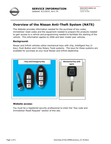
Repair Flow ChartNoDelayed engagement (longer than 3seconds) has been confirmedYesThis bulletindoes not applyCheck for applicableTCM reprogramIf reprograming applies,reprogram the TCMRemove the control valve (valve body),inspect the CVT beltNo evidence ofbelt slippageEvidence ofbelt slippageReplace thevalve bodyReplace theCVT assemblySee page 26for importantpre-authorization2/26NTB15-085b
SERVICE PROCEDURETCM ReprogrammingNOTE: Most instructions for reprogramming with CONSULT-III plus (C-III plus) aredisplayed on the CONSULT PC screen. If you are not familiar with the reprogramming procedure, click here. This will linkyou to the "CONSULT- III plus Reprogramming" general procedure.CAUTION: Connect the GR8 to the vehicle battery, set to “power supply” mode.If the vehicle battery voltage drops below 12.0V or rises above 15.5V duringreprogramming, the TCM may be damaged. Be sure to turn OFF all vehicle electrical loads.If a vehicle electrical load remains ON, the TCM may be damaged. Be sure to connect the AC Adapter.If the CONSULT PC battery voltage drops during reprogramming, the processwill be interrupted and the TCM may be damaged. Turn OFF all external Bluetooth devices (e.g., cell phones, printers, etc.)within range of the CONSULT PC and the VI. If Bluetooth signal waves arewithin range of the CONSULT PC during reprogramming, reprogramming maybe interrupted and the TCM may be damaged.3/26NTB15-085b
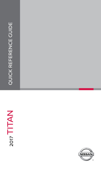
1. Connect the CONSULT PC to the vehicle to begin the reprogramming procedure.2. Start C-III plus.3. Wait for the plus VI to be recognized. The serial number will display when the plus VI is recognized.4. Select Re/programming, Configuration.Step 3:plus VI isrecognizedStep4Figure 15. Follow the on-screen instructions and navigate the C-III plus to the screen shown inFigure 2 on the next page.4/26NTB15-085b
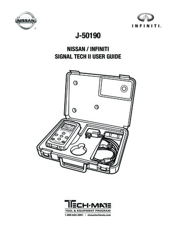
6. When you get to the screen shown in Figure 2, confirm this bulletin applies as follows.A. Find the TCM Part Number and write it on the repair order.NOTE: This is the current TCM Part Number (P/N).6A: Current TCM P/NTRANSMISSION31036 -Figure 2B. Compare the P/N you wrote down to the numbers in the Current TCM Part Numbercolumn in Table A below. If there is a match, this bulletin applies. Continue with the reprogrammingprocedure. If there is not a match, go to page 11, Control Valve (Valve Body) Removaland CVT Belt Inspection.Table AMODEL2013 Altima(4-cyl engine only)CURRENT TCM PART NUMBER BEFOREREPROGRAMMING: 31036 3TA0A, 3TA4A3TA4B3TA4C, 3TA9C3TY0A, 3TY1A2014-2015Altima(4-cyl engine only)9HM0A, 9HM0C, 9HM0D5/26NTB15-085b
7. Follow the on-screen instructions to navigate C-III plus and reprogram the TCM.NOTE: In some cases, more than one new P/N for reprogramming is available. If more than one new P/N is available, the screen in Figure 3 displays. Select and use the reprogramming option that does not have the message“Caution! Use ONLY with NTBXX-XXX”. If you get this screen and it is blank (no reprogramming listed), it means there is noreprogramming available for this vehicle. Close C-III plus, and then go to page 11,Control Valve (Valve Body) Removal and CVT Belt Inspection.TRANSMISSIONFigure 3IMPORTANT: If C-III plus locks up or freezes at this point or displays “cannotcomplete reprogramming, the CONSULT PC is set up with User Rights.Reprogramming can be completed with Administrator log in”, the TOUGHBOOKsettings need to be changed so that Users have full access rights. See yourDealership’s IT System Administrator for details.6/26NTB15-085b
8. When the screen in Figure 4 displays, reprogramming is complete.NOTE: If the screen in Figure 4 does not display (indicating that reprogramming did notcomplete), refer to the information on the next page.9. Disconnect the battery charger from the vehicle.10. Select Next.Step10Figure 4NOTE: In the next step (page 9), you will perform Erase All DTCs. DTC erase is required before C-III plus will provide the final reprogrammingconfirmation report.7/26NTB15-085b
TCM Recovery:Do not disconnect plus VI or shut down C-III plus if reprogramming does notcomplete.If reprogramming does not complete and the “!?” icon displays as shown inFigure 5: Check battery voltage(12.0–15.5 V). Ignition is ON, engine OFF. External Bluetooth devicesare OFF. All electrical loads are OFF. Select retry and follow theon screen instructions. “Retry” may not go throughon first attempt and can beselected more than once.Figure 5If reprogramming does not complete and the “X” icon displays as shown inFigure 6: Check battery voltage(12.0 – 15.5 V). CONSULT A/C adapter isplugged in. Ignition is ON, engine OFF. Transmission is in Park. All C-III plus / VI cables aresecurely connected. All C-III plus updates areinstalled. Select Home, and restartthe reprogram procedurefrom the beginning.Figure 68/26NTB15-085b
11. Follow the on-screen instructions to Erase All DTCs.12. When the entire reprogramming process is complete, the screen in Figure 7 will display.13. Verify the before and after part numbers are different.14. Print a copy of this screen (Figure 7) and attach it to the repair order for warrantydocumentation.15. Select Confirm.31036 -Step1331036 -TRANSMISSIONStep14Step15Figure 716. Return C-III plus to the Home screen.17. Turn OFF C-III plus and the vehicle ignition.18. Disconnect C-III plus from the vehicle.9/26NTB15-085b
Exploded View(Total of 9 bolts)Figure 8Terminal cord assemblyControl valve (valve body)O-ringOil strainer assemblyOil pan gasketOil panDrain plugDrain plug gasketTwo original magnetsSpring washerManual plateLip sealSnap ringOverflow plugO-ringTransaxle (CVT) assembly10/26NTB15-085b
Control Valve (Valve Body) Removal and CVT Belt Inspection1. Remove the valve body. Before lifting the vehicle: Place the transmission gear selector in Neutral. Leave the driver door unlatched. A step further in the procedure may require it. Refer to the ESM, section TM – Transaxle & Transmission / RE0F10D, for valvebody removal.NOTE: The number ‘7’ is on the head of all bolts that need to be removed for valvebody removal. Do not remove any bolt that does not have the number ‘7’.CAUTION: Never allow any chemicals or fluids other than NS-3 CVT fluid orequivalent to enter the CVT assembly. Never allow any foreign debris, dust,dirt, etc. to enter the CVT assembly. For additional information, see video # 544: “CVT Belt Inspection”. This video islocated under the TECH TRAINING GARAGE VIDEOS tab in Virtual Academy.11/26NTB15-085b
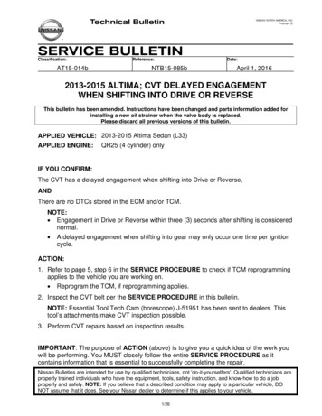
2. Secure the front right tire with a suitablestrap. This will assist in making the belt turn.3. Mark the front left tire with a suitablemarking. This will assure all 360 of the belt isinspected.Figure 94. Using borescope J-51951 with mirrorattachment, inspect the entirety of the twosides of the belt that come in contact withthe pulleys (see page 14, Figure 15).Reference the pictures on pages 14-18for comparison.BeltPulleyCaseNOTE: Be sure to remove the protective filmfrom the mirror before the first use. Step 4aClean the camera lens and mirrorbefore each inspection. Use 90%isopropyl alcohol, and a lens swabfrom Lens Swab packet J-51963 listedin PARTS INFORMATION.Step 4cFigure 10Before inspecting, make sure thecamera handle’s AA batteries arefresh and the LCD monitor’s batteryis charged.Cameraflexible tubeFronta. Insert the camera lens between theCVT case and pulley where shown inFigures 10 and 11. Insert the lens approximately seven(7) inches, and then view the sideof the belt that contacts the pulley.Figure 1112/26NTB15-085b
b. Slowly and carefully turn the front lefttire one full turn in the forward rotationto view all of the belt. Holding the borescope with onehand allows for turning the tire withthe other hand (see Figure 12).CAUTION: If the tire is rotated in therearward rotation, the camera lensmay get caught between the belt andpulley.c. If the inspection result is OK, inspectthe other side of the belt. Figure 12Insert the camera lens in thesecond location where shownin Figures 10 and 13, and thenperform step 4b again.d. If the inspection result is OK 360 onboth sides of the belt, skip to step 5 onthe next page. If any evidence of belt slippageis found, go to step 4e, and thenstep 6. For additional information, seevideo # 544: “CVT Belt Inspection”.This video is located under theTECH TRAINING GARAGEVIDEOS tab in Virtual Academy.e. Once CVT replacement is determinedas required, use borescope J-51951 torecord a 15 second or less continuousvideo of the most severe evidence ofbelt slip and the VIN on the F.M.V.S.S.certification label (VIN label). SeeFigure 14.NOTE: This required video must beattached to the Powertrain Call CenterCVT Preauthorization Form (in ASIST)prior to calling for authorization.Failure to submit a continuous videowill cause immediate denial of requestfor replacement.13/26PulleyFrontFigure 13VINlabelFigure 14NTB15-085b
Before starting to record, make sure the camera handle’s AA batteries are fresh andthe LCD monitor’s battery is charged.The whole video will show as backward, or reversed mirror image. This is okay.The required video must show clear evidence of belt slippage and be 15 seconds orless.5. If the belt inspection result is OK, replace the valve body. There is no need for pictures or video showing “OK” belt surfaces.For valve body replacement, go to page 19, Control Valve (Valve Body)Installation.6. If the belt inspection result is NG, replace the CVT assembly. Get authorization to replace the CVT assembly (see page 26). Make sure to perform step 4e on page 13. For CVT assembly replacement, refer to the appropriate ESM, section TM –Transaxle & Transmission / RE0F10D.IMPORTANT: Perform "ADDITIONAL SERVICE WHEN REPLACING TRANSAXLEASSEMBLY". Refer to TM – Transaxle & Transmission / RE0F10D / BASIC INSPECTION:o Check for fluid leakage.o Install Write IP Characteristics to the TCM; see NTB12-103. The CVT unit requiring replacement will need to be reassembled for Nissan partsreturn/collection.7. Flush the CVT cooler(s).IMPORTANT: A CVT Cooler flush is required after a valve body or CVT assemblyreplacement. Refer to bulletin NTB15-013 to perform CVT Cooler flush.Inspect these sidesDo not inspectthese sidesFigure 1514/26NTB15-085b
Figure 16: New beltFigure 17: Close-up of section to be inspected15/26NTB15-085b
Pictures in Figures 18 and 19 were taken with borescope J-51951.OKVisuallinesFigure 18: Belt is OKOKVisuallinesFigure 19: Belt is OK16/26NTB15-085b
NGScuffingFigure 20: Example of NG beltNGLines“smeared”Figure 21: Example of NG belt17/26NTB15-085b
Pictures in Figures 22-24 were taken with borescope J-51951.NGFigure 22: Example of NG beltNGFigure 23: Example of NG beltNGFigure 24: Example of NG belt18/26NTB15-085b
Control Valve (Valve Body) Strainer and Pan InstallationIMPORTANT: This section may contain different style parts than what were originallyinstalled in the CVT. Pay careful attention, REASSEMBLY MAY NOT BE IDENTICALTO DISASSEMBLY.CAUTION: Handle the valve body carefully.1. Discard the oil strainer bracket (Figure 25).2. Install a new lip seal. Do NOT reuse the old lip seal (Figure 26).NOTE: Apply a small amount of petroleum jelly to the lip seal to keep it in place on theCVT.Oil strainerbracketLip sealFigure 25Figure 263. Install the Control Valve with nine (9)mounting bolts (Figure 27).IMPORTANT: Leave Four (4)holes blank at this step.boltCAUTION: Make sure the wiring harnessis not in the way / does not get pinched. 54 mm long bolt– 7 pieces 44 mm long bolt– 2 piece 25 mm long bolt– 2 piece25 mm bolts44 mm boltsWiring harnessCAUTION: These two bolts areinstalled WITHOUT the strainerbracket.Figure 27 Bolt torque: 8.0 N m (0.81 kg-m,70.8 in-lb.)19/26NTB15-085b
4. Replace the metal bracket of the temperature sensor as follows:NOTE: The new bracket will be oriented the same way the old bracket was.a. Cut the plastic zip tie with an appropriate tool to remove the temperature sensorbracket from the terminal harness assembly. (Figure 28).CAUTION: Cut the plastic zip tie over the metal bracket to avoid damage to thetemperature sensor.b. Discard the removed bracket and plastic zip tie.c. Use the plastic zip tie from Parts Information to attach the new temperature sensorbracket to the temperature sensor of the terminal connector harness.IMPORTANT: Locate the plastic zip tie at the center notch of three notches on thetemperature sensor.d. Cut off plastic zip tie excess.TemperaturesensorMetal bracketPlastic zip tie in center notchFigure 2820/26NTB15-085b
5. Connect the electrical harness connector(Figure 29).HarnessconnectorFigure 296. Install the CVT fluid temperature sensorbracket to the valve body with one (1)bolt (Figure 30).NOTE: Leave one (1) bolt hole blank as itwill be used to secure the oil strainer at alater step. Bolt torque: 8.0 N m (0.81 kg-m, 70.8in-lb.) Bolt length: 54 mm1 boltFigure 307. Install the new oil strainer with its newO-ring seal with two (2) bolts (Figure 31).NOTE: replacement strainer maybe adifferent shape. Bolt torque: 8.0 N m (0.81 kg-m, 70.8in-lb.). 54 mm long bolt54 mmbolts- 2 pieces.Figure 3121/26NTB15-085b
8. Install the manual plate, lock washer, andnut (Figure 32).NOTE: Make sure the manual plate fitsinto the slot of the manual valve beforeapplying torque to the nut. Reuse the existing manual plate, lockwasher, and nut. Nut torque: 22.5 N m (2.29 Kg-m,16.6 ft-lb.)Slot and manualplate endManual plateLock washerNutManual valveFigure 329. Clean the original oil pan and magnetswith a suitable cleaner. Visible debrisshould not be present at re-assembly.10. Reassemble the original magnets to thepan.NOTE: Return the magnets to theiroriginal locations.11. Install a new oil pan gasket to the pan.12. Install the oil pan bolts (see Figure 33). Reuse the existing pan bolts. Oil pan bolts torque: 8.0 N m, (0.81Kg-m, 70.8 in-lb.)13. Install a new drain washer to the drainplug on the oil pan.Figure 3322/26NTB15-085b
14. Fill the CVT assembly with NS-3 CVT fluid or equivalent. Refer to the ESM, section TM – Transaxle & Transmission / RE0F10D,for CVT fluid filling.15. IMPORTANT: Install Write IP Characteristics to the TCM; see NTB12-103. Refer to TM – Transaxle & Transmission / RE0F10D / BASIC INSPECTION, andperform ADDITIONAL SERVICE WHEN REPLACING TRANSAXLE ASSEMBLY. Check for fluid leakage. Attach the QR label with the new calibration data onto the transmission rangeswitch (inhibitor switch).o See Figure 34 and 35 below.o A QR Label and CD-R are included with the replacement valve body.16. Erase the DTC.Air cleanerintake ductInhibitorswitch------Valve cover-----QR labelFigure 34Figure 3523/26NTB15-085b
PARTS INFORMATIONDESCRIPTIONCVT ASSEMBLY (1)VALVE ASSEMBLY-CONTROL(valve body) (3)STRAINER ASSY-OIL, AUTO TRANSBRACKET (for temperature sensor)BAND (zip tie for sensor bracket)GASKET-OIL PANSEAL-LIPWASHER-DRAINSEAL, O-RING (fluid filler plug gasket)PART 6-3VX0B1111111999MP-NS300PNS-3 CVT Fluid (4) (5)As neededLens Swab (6) (7)J-51963As needed(1) If the CVT assembly is being replaced, no other parts in the table above, except NS-3CVT fluid or equivalent, are needed.(2) Refer to the electronic parts catalog (FAST or equivalent) for the correct part number.(3) Includes QR Label, CD-R, and Control Valve Assembly.(4) For warranty repairs, Nissan NS-3 CVT Fluid must be used. For customer pay repairs,Nissan NS-3 CVT Fluid or an equivalent is recommended.(5) NS-3 CVT Fluid can be ordered through the Nissan Maintenance Advantage program:Phone: 877-NIS-NMA1 (877-647-6621) or Website: Order via link on dealer portalwww.NNAnet.com and click on the “Maintenance Advantage” link.(6) Lens swabs are available from Tech Mate online: www.nissantechmate.com, or byphone: 1-800-662-2001.(7) Shop supply.Tech Cam J-51951Lens swab J-51963(not part of J-51951)Figure 28Remove protectivefilm before first useAdditional kits and components of Tech Cam J-51951 are available from Tech Mate online:www.nissantechmate.com, or by phone: 1-800-662-2001.24/26NTB15-085b
CLAIMS INFORMATIONNOTE: Refer to CVT Assembly Replacement Approval Procedures (on the next page)before submitting a claim.Only Claim if TCM requires reprogrammingSubmit a Primary Part (PP) type line claim using the following claims coding:OPERATIONPFPTCM Reprogramming(1)OP CODE SYMJE99AAZEDIAGFRT32(2)(1) Refer to the electronic parts catalog (FAST or equivalent) and use the TCM part number(31036 - *****) as the PFP.(2) Reference the current Nissan Warranty Flat Rate Manual and use the indicated FlatRate Time.NOTE: FRT allows adequate time to access DTC codes. No other diagnosticprocedures subsequently required. Do NOT claim any diagnostic OP Codes with thisclaim.If belt inspection shows no signs of belt slip, OKSubmit a Primary Part (PP) type line claim using the following claims coding:DESCRIPTIONRPL CVT CONTROL VALVE ASSYPFP(3)OP CODEJD48AASYM DIA FRTZE32(4)(3) Reference the Parts Information Table and use the applicable Control Valve AssemblyPart Number (31705-*****) as the Primary Failed Part.(4) Reference the current Nissan Warranty Flat Rate Manual and use the indicated FlatRate Time.NOTE: FRT allows adequate time to access DTC codes. No other diagnosticprocedures subsequently required. Do NOT claim any diagnostic OP Codes with thisclaim.AndDESCRIPTIONOP CODEFRTInspect CVT Belt, Belt OKJX37AA0.3ORClaims Information continued on the next page.25/26NTB15-085b
Clams Information Continued:If belt inspection shows signs of belt slip, NGSubmit a Primary Part (PP) type line claim using the following claims coding:DESCRIPTIONCVT R&RPFPOP CODESYMDIA(1)JD01AAJD023AZE32FRT(2)CVT TROUBLE DIAGNOSISJX22AA0.5(1) Reference the electronic Parts Catalog (FAST or equivalent) and use the CVT assemblypart number for the vehicle being repaired as the Primary Failed Part.(2) Reference the current Nissan Warranty Flat Rate Manual and use the indicated FlatRate Time.NOTE: FRT allows adequate time to access DTC codes. No other diagnostic proceduressubsequently required. Do NOT claim any diagnost
VIDEOS tab in Virtual Academy. e. Once CVT replacement is determined as required, use borescope J-51951 to record a 15 second or less continuous video of the most severe evidence of belt slip and the VIN on the F.M.V.S.S. certification label (VIN label). See Figure 14. NOTE: This requ