Transcription
INVESTIGACIÓNREVISTA MEXICANA DE FÍSICA 56 (4) 317–322AGOSTO 2010Universal testing machine for mechanical properties of thin materialsE. Huerta , J.E. Corona, and A.I. OlivaCentro de Investigación y de Estudios Avanzados del Instituto Politécnico Nacional,Unidad Mérida, Departamento de Fı́sica Aplicada,Apartado Postal 73-Cordemex, 97310 Mérida Yucatán, México,e-mail: microsco@mda.cinvestav.mxF. AvilésCentro de Investigación Cientı́fica de Yucatán A.C., Unidad de Materiales,Calle 43 No. 130 Col. Chuburná de Hidalgo, 97200, Mérida Yucatán México.J. González-HernándezCentro de Investigación en Materiales Avanzados, S.C.,Av. Miguel de Cervantes 120 Complejo Industrial Chihuahua, 31109 Chihuahua, Chihuahua, México.Recibido el 26 de marzo de 2010; aceptado el 8 de junio de 2010In this work, the design, construction, calibration and compliance measurement of a universal testing machine for tension tests of materials infilm geometry are presented. A commercial load cell of 220 N and sensitivity of 1.2345 mV/V is used to measure the applied load. Materialstrain is measured by movement of the crosshead displacement of the machine with a digital indicator with 0.001 mm resolution and 25 mmmaximum displacement, connected to a PC through an interface. Mechanical strain is achieved by an electric high precision stepper motorcapable to obtain displacement velocities as low as 0.001 mm/s. The stress-strain data acquired with a GPIB interface are saved as a filewith a home-made program developed in LabView 7.0. Measurements of the elastic modulus and yield point of a commercial polymer film(500 HN Kapton) were used to validate the performance of the testing machine. The obtained mechanical properties are in good agreementwith the mean values reported by the supplier and with the values obtained from a commercial machine, taking into account the limitationsof thin film testing and experimental conditions.Keywords: Universal testing machine; elastic modulus; thin films; compliance.En este trabajo se discute el diseño, la construcción, la calibración y la medición de la complianza de una máquina universal para pruebasde tensión de materiales en geometrı́a de pelicula. La carga aplicada es medida con una celda de carga comercial de 220 N y sensitividad de1.2345 mV/V. La elongación de la muestra es medida a través del desplazamiento del cabezal de la máquina con un indicador de carátuladigital con resolución de 0.001 mm y desplazamiento máximo de 25 mm, conectada a una PC a través de una interfase de puerto serial. Ladeformación mecánica es conseguida con un motor a pasos de alta precisión capaz de conseguir velocidades tan bajas como 0.001 mm/s. Losdatos adquiridos a través de una interfase GPIB en tiempo real son guardados en un archivo usando un programa de diseño propio desarrolladoen LabView 7.0. El módulo de elasticidad y el punto de fluencia medidos en una pelicula polimérica comercial (Kapton 500 HN) fueronutilizados para evaluar el desempeño de la máquina construida. Los valores de las propiedades mecánicas obtenidas muestran buen acuerdocon los valores reportados por el proveedor y con los resultados obtenidos con una máquina comercial, considerando la geometrı́a de capadelgada.Descriptores: Máquina universal de pruebas; módulo de elasticidad; capas delgadas; complianza.PACS: 07.10.Pz; 62.20.de; 81.05.Bx; 81.70.Bt1.IntroductionNew methodologies to measure the physical properties ofthin films are currently required. Particularly, reported mechanical properties of materials at these dimensions are currently controversial in the scientific literature. Thus, it isnecessary to propose techniques for determining mechanicalproperties of thin films, such as elastic modulus, Poison’s ratio and strength. Properties of materials at micro and nanoscale are of considerable interest because of the unique properties associated with small volumes. These unique properties are increasing the importance of thin films and nanostructured materials used in several technological applications. Atpresent, flexible electronics onto polymer substrates [1-2] arebeing developed for many applications, such as electronictextiles [3] and paper-like displays [4-5]. These electronicdevices are normally subjected to high external stresses andlarge strains due to the flexible material used as substrate [6].As it is well known, the film properties can be quite differentfrom the bulk properties [7]. Thus, knowledge of the mechanical properties of nanostructured materials is essential toobtain functional and reliable electronic devices. Differentmethods have been proposed to investigate the mechanicalproperties of these thin materials. The most common methods are based on X-ray diffraction [8], interferometry [9] andmost recently, nanoindentation [10-11]. These methods oftenrequire sophisticated instrumentation and do not compel withthe conventional definition of mechanical properties, whichare defined in terms of conventional tensile testing. In bulkgeometry, the mechanical properties are commonly obtained
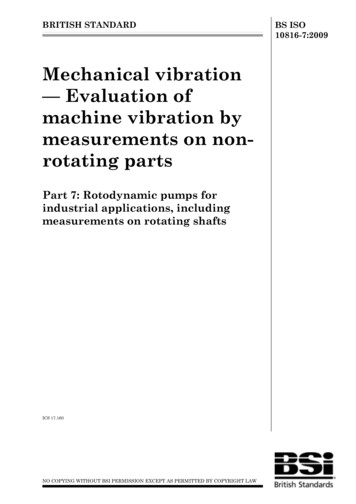
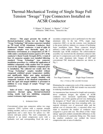
318E. HUERTA, J.E. CORONA, A.I. OLIVA, F. AVILÉS, AND J. GONZÁLEZ-HERNÁNDEZAs is shown in Fig. 1, the testing machine is composedof five main parts:i) the main frame,ii) the drive system,iii) the movable crosshead,iv) the load cell, andv) the digital indicator.F IGURE 1. 3D view of the universal testing machine.through tensile testing, and there exists different commercialmachines for characterization of bulk materials [12-15]. Tensile testing is an effective way to investigate the mechanicalproperties of materials and it is a well established techniquefor bulk sample characterization. However, tensile testing isnot easily implemented for micro and nano-structured materials due to the small dimensions of the specimen. At present,there exist these testing machines for materials in film geometry [16-18] but they are expensive and its flexibility to makemodifications is limited. In this work, the design, construction, calibration and compliance determination of a universaltesting machine, specially designed for tensile tests of materials in film geometry is discussed. Our universal testing machine is designed to produce small deformations at low velocities and, consequently, high resolution. The testing machineis sensitive to small loads and permits to obtain the stressstrain curves for materials in film geometry. Elastic modulus, yield point, and maximum stress can be obtained fromsamples of up to about 10 cm length. An important featureof this device is the simplicity to exchange components according to the user requirements: the low cost, low machinecompliance and the high resolution obtained. This machinecan also be adapted for compression testing with appropriatesamples and grips. However, compression testing will not beaddressed in this work.The testing machine is mainly made of stainless steel, excepting some frictional elements like the gears, which were madeof bronze.The main frame includes the rectangular base where thegearbox is placed, the fixed crosshead and the two verticalparallel columns. The drive system includes a stepper motorwith variable speed. The gearbox is formed by a worm shaft,and two worm gears, which moves the two drive screws. Themovable crosshead is integrated by the bottom grip, two conical fastener tools with internal thread and an adjustable conical ring. The conical fastener tools provide stabilization tothe movable crosshead when moving along the drive screws.The load cell used is a LCC-HTC-50 dual stud cell from LoadCell Central Co. [19] which withstands a 220 N maximumload with a sensitivity of 1.2345 mV/V. The load cell can beused for tension or compression testing, it is located on theupper side of the frame and supports the upper grip. The digital indicator measures the crosshead displacement and consists of a digital micrometer from Starret [20] with 0.001 mmof resolution, which is connected with an RS232 interface toa personal computer to acquire data.To achieve high resolution in the measurements, thedevice includes a stepper motor used to control both velocity and torque. The drive system achieves displacements as small as 0.001 mm and velocities between 0.001and 0.1 mm/s. Two stainless-steel grips (one fixed to the load2. Design and constructionThe testing machine was designed to determine the stressstrain curves of thin materials such as polymers and particularly metallic films deposited onto polymeric substrates.Figure 1 shows a 3D illustration of the designed devicewith 15 cm wide, 55 cm length and 45 cm high as total dimensions. The equipment is capable of analyzing samples upto 10 cm of length. The mechanical design minimizes effectsof load introduction in the main frame, drive screws, and therelative movement between the movable crosshead and thedrive screws.F IGURE 2. Photograph of the universal testing machine. The different components shown in Fig. 1 such as the drive system, loadcell, electronic indicator, movable crosshead and stepper motor canbe observed.Rev. Mex. Fı́s. 56 (4) (2010) 317–322
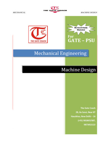
UNIVERSAL TESTING MACHINE FOR MECHANICAL PROPERTIES OF THIN MATERIALS3.1.319Calibration and data acquisitionThe calibration of the load cell was conducted by collectingdata of different known applied loads (weights) and measuring its corresponding output voltage.Calibration measurements were conducted by steps overa range of 0 to 12 N with an elapsed-time of 1 min betweeneach calibrated load in order to avoid hysteretic effects; i.e,the voltage returns to cero value after removing the load. Aseries of calibrated loads were applied in increasing order.The output voltage of the load cell was captured througha high-resolution programmable voltmeter HP 3458A. Figure 3 shows the obtained linear behavior between the applied load (P) and the output voltage (V) as obtained fromthe load cell. The equation describing this relationship canbe expressed by:F IGURE 3. Calibration curve showing the relation between appliedload and the voltage response of the load cell.F IGURE 4. Frontal panel of the program developed in LabView.The program permits to control the excitation voltage and acquirethe applied force and the displacement.cell and the other on the movable crosshead) are used to holdthe samples. The grips were designed with smooth surfacesto avoid damage to the soft and thin samples. Each grip iscomposed by a fixed part and a movable plate joined withtwo screws to uniformly press the samples. This holding system avoids sliding between sample and grips during tensiletests. The design of this universal testing machine permitsthe interchange of the different parts such as the load cell,grips and drive screws, in order to extend the user requirements. Figure 2 shows a photograph of the universal testingmachine. Stress-strain data are captured and saved in a datafile through a GPIB interface controlled with a home-madeprotocol programmed in LabView 7.0.3.PerformanceIn order to determine the performance of the proposed testing machine, following the work done to calibrate the loadcell, the methodology used to obtain the compliance of themachine, and the data acquisition are discussed.P 12.8366V 0.06574(1)where the applied load P is given in Newtons and the outputvoltage V in milivolts.This linear behavior confirms the information providedby the manufacturer and permits to obtain a relationship tobe used into the program as a transduction signal.According to the supplier, the load cell can support maximum loads of 220 N, but it is not desirable to reach this limitgiven that supplier guarantees a linear deviation of 0.15% atfull load.The data acquisition system uses a GPIB interface of National instruments to control the applied excitation voltageof the power supply and to collect the corresponding outputvoltage of the voltmeter. The GPIB interface is controlledwith a home-made program developed in Labview 7.0. Figure 4 shows the frontal panel of the implemented programand the different parameters used to obtain the stress-straincurve. The designed program permits to select the acquisitiontime, step-time, and the excitation voltage for the load cell,and requires the length, width, and thickness of samples asentries. The force-displacement and stress-strain curves areplotted in real time during testing. Using this program, parameters as data acquisition time, displacement, and appliedforce can be captured and saved in real time for subsequentanalysis.3.2.Machine compliance determinationIn mechanical testing of materials, when a strain gage or anin-situ element cannot be used to measure the real materialstrain, it is customary to use the machine crosshead displacement to measure the applied strain. Measurements conductedby crosshead displacement need to be calibrated by takinginto account the machine compliance Cm . In order to calibrate the machine compliance (Cm 1/km δ/P, where kmis the stiffness constant, δ the crosshead displacement, andP the applied load), a specific experiment was conducted bytensile testing by using a stiff metallic sample (as comparedRev. Mex. Fı́s. 56 (4) (2010) 317–322
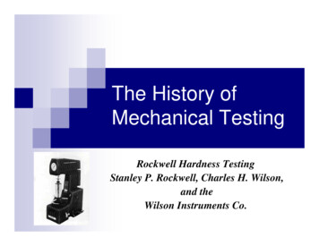
320E. HUERTA, J.E. CORONA, A.I. OLIVA, F. AVILÉS, AND J. GONZÁLEZ-HERNÁNDEZF IGURE 5. Rigidities obtained from the universal testing machineto calculate the total and material compliances.F IGURE 7. Six stress-strain curves obtained from the Kapton foilthrough our home-made machine, showing the elastic and plasticzone of the polymer.F IGURE 8. Stress-strain curves for Kapton samples obtained witha Shimadzu testing machine under similar conditions than Fig. 7.F IGURE 6. Displacement of the movable crosshead vs. time duringa tensile test.with soft materials). Compliance was obtained through tensile testing by using aluminum samples with 35 mm gagelenght, 4.2 mm wide and 0.46 mm thick. The tensile test wasdone by applying loads from 0 to 140 N, limited by the capacity of the load cell. Strain was measured simultaneouslyby the machine crosshead displacement and by a commercial strain gage (Vishay ED-DY-062AK-350) bonded to themid-part of the sample. The strain gage was connected toa Vishay model P3 strain indicator to record the gage signal. Half bridge configuration was used in order to minimizetemperature effects. The total compliance measured by thecrosshead displacement (CT ) is a sum of the compliance ofthe analyzed material (CAl ) and the compliance of the machine (Cm ), simulating a series spring system. Since CT andCAl are measured during the experiment, the next relationcan determine the machine compliance:CT Cm CAl(2)Figure 5 shows load-displacement curves for the analyzedsample measured by the machine-crosshead and strain gage(simultaneously). The values of the compliances (inverseof the load-displacement slopes) measured by both methods are CAl 0.43 µm/N and CT 0.59 µm/N. According toEq. (2), the measured values yield a machine compliance ofCm 0.16 µm/N. As it will be further discussed in connectionwith experiments on Kapton, the compliance of our machineis significantly low, confirming that our universal testing machine is appropriated to obtain mechanical properties of materials with low modulus, thin films, and polymers.The machine compliance value is constant and needs tobe considered to determine the real value of the elastic modulus of a material under test, if the crosshead displacementRev. Mex. Fı́s. 56 (4) (2010) 317–322
UNIVERSAL TESTING MACHINE FOR MECHANICAL PROPERTIES OF THIN MATERIALSis used to measure strain. To determine the real elastic modulus (E) of a material under axial tension it is necessary totake into account the machine compliance. This can be doneusing a spring-in-series system. The elastic modulus as determined with the machine crosshead displacement (ET ) needsto be corrected to obtain the real modulus E, by the relation [21,22]:E ET1 Cm ET AL(3)where Cm is the measured machine compliance, A the sectional area, and L the gage length.4.Results and validationA commercial polymer, 500 HN Kapton, was initially usedas a benchmarking specimen by its well-known propertiesreported by the DuPont Co. supplier [23]. Tensile testswere conducted using rectangular geometries of Kapton filmsof 40 mm length, 5 mm wide and 0.125 mm thick. The gagelength of the samples was always 20 mm. The displacementvelocity of the movable crosshead during tensile experimentswas maintained at 0.01 mm/s in all cases.Figure 6 shows a plot of the displacement of the movable crosshead vs. time, where high stability can be observedwhen it moves along the drive screw with the sample gripped.From Fig. 6, a constant behavior of the velocity and very lowmechanical noise during the crosshead displacement is evident. Therefore, the movement of the movable crossheaddoes not have additional effects, such as vibrations or speedchanges that could affect the tensile tests.Figure 7 shows a group of six superimposed stress-straincurves as obtained from different samples of the Kapton foil.The six curves are difficult to visualize given their high reproducibility. From this figure, it can be observed that Kapton has a linear elastic behavior below 1.8% strain. The totalstrain applied to the samples was always 24%, which is farfrom the ultimate strain reported by the supplier (72%). Thishigh strain can not be achieved by our machine giving themechanical limits of the device.In Fig. 7, the initial slope of the curve (elastic zone) corresponds to the elastic modulus. The value of the real elasticmodulus (E) calculated from the different stress-strain curvesand corrected through Eq. 3 were estimated in 2.7 0.1 GPaas mean value. This value is 1.1% larger than the ET valuemeasured from the stress-strain curves directly obtained fromthe machine. The low dispersion of data affirms the high reproducibility of the measurements inducted on Kapton foils.The yield point (σY ) was determined as the stress obtainedat 3% of the deformation (εY ) as shown in Fig. 7. Themean value of this parameter estimated in 61.0 1.0 MPa.The stress obtained at 24 % strain was ranged from 146.1to 149.3 MPa, with an average of 147.6 1.0 MPa. For comparison, the mean values of the elastic modulus and the yield321point for Kapton as provided by the supplier are 2.5 GPa and69 MPa at 3% of strain [23], respectively. The small differences measured by our testing machine (9 and 11%) can bedue to the difference in the geometry of the samples used bythe manufacturer (dog-bone), according to the ASTM D-88291 standard, and the different test velocity (10 mm/s) used.In order to compare our results, Fig. 8 shows results of foursimilar samples of Kapton tested in a commercial Shimadzumachine model AGI-100, with a load cell of 500 N, using acrosshead speed of 0.01 mm/s. From results, the elastic modulus and the yield point were estimated in 2.6 0.2 GPa and55.4 1.2 MPa, respectively. Thus, although the values aresomewhat similar, it is very difficult to obtain the same valuesthan those reported by the supplier, if different test conditionsare used.It is known that thickness and specimen length can affect the stress-strain curves of materials, especially those infilm geometry [24]. Different test conditions can cause variations on the measurements of mechanical properties of thepolymers. For example, notorious effects in the plastic zonedue to the testing velocity have been reported in ref [25]. Inseveral reports [26,27] the analyzed samples deviate from thesize and geometries required by the ASTM standards, andsometimes the different values measured of certain mechanical properties can not be comparable. Thus, testing of microand nano-materials demands to establish new standards andfix the test conditions, size and, geometry of the samples, toobtain reproducible mechanical properties.5.ConclusionsThe design, construction, calibration and compliance measurement of a universal testing machine for tensile tests onthin an
through tensile testing, and there exists different commercial machines for characterization of bulk materials [12-15]. Ten-sile testing is an effective way to investigate the mechanical properties of materials and it is a well established technique for bulk sample chara