Transcription
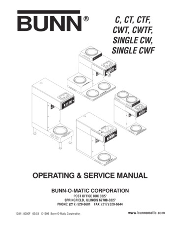
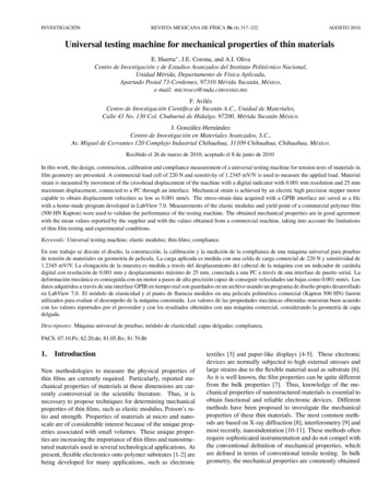
Thermal-Mechanical Testing of Single Stage FullTension “Swage” Type Connectors Installed onACSR ConductorE. Khansa*, D. Stanton*, A. Maurice**, Z. Peter**Affiliation: *DMC Power, **Kinectrics Inc.Abstract - This paper presents the results ofthermal-mechanical cycling test on Single Stage“Swage Technology” full tension connectors installedon 795 kcmil ACSR (Aluminum Conductor, SteelReinforced) “Drake” conductor. A total of eight (8)connector samples were thermally aged, in alaboratory environment, at a temperature of 150 Cwhile under a mechanical tension equal to 25% of theconductor’s Rated Tensile Strength (RTS). A total offour (4) connector samples were installed followingstandard “Swage Technology” type connectorinstallation procedure (i.e. without the application ofinhibitor compound), while another four (4) samplesreceived the application of inhibitor compound priorto installation. The collected test results show the“Swage Technology” samples installed withoutcompound exhibited greater temperature stabilityand significantly higher post aging mechanicaltension performance than samples installed withcompound. Analysis of the chemical composition ofboth the aged and unaged inhibitor is presented inaddition to x-ray images of sample “Swage” typeconnectors.Index of terms - swage connectors, single stageconnector, thermal aging, thermal-mechanicaltesting, tensile load test, inhibiting compound,contact resistance, high temperature.I.INTRODUCTIONConventional crimp type connectors utilize two stageconnector (TSC) systems with a separate strengthholding member, such as a steel eye loop, for dead endapplications and a steel sleeve for splices (i.e. fulltension mid-span joints). The steel components aresubjected to an initial compression cycle with ahydraulic tool and corresponding fixed die and asecondary compression cycle is performed over the outeraluminum tube. In the late 1970s, single stageconnectors (SSC), or one die systems, were introducedto the power delivery industry as a means of facilitatingfaster installation times. These connector designsutilized a collet which encapsulated the steel core ofbimetallic type ACSR conductor. The collet/conductorassembly was inserted into the aluminum connector tubeand one (1) compression cycle with a fixed die is appliedto the outer aluminum tube. Images of SSC andconventional TSC dead-end connectors are shown inFig. 1.Two Stage ConnectorSingle Stage ConnectorFIG. 1. TYPICAL TSC AND SSC SYSTEMSEliminating the compression cycle of the connector steelsleeve directly on the ACSR steel strands was successfulin reducing installation times.As transmission lines increased in length and economicsdrove conductor designs, the number of ACSRconductor sizes increased significantly. Multipleconductor sizes of this quantity proved very challengingfor designers of “fixed” tube or extruded tube fittings.Due to long production time from extruding mills, rawmaterial inventory cost of processed tubes and theupfront cost of extrusion dies, a concerted effort wasmade to maximize the number of conductor sizesassigned to a given tube size. The effects of this “rangetaking” approach yielded considerable differences in thearea of reduction of a particular fitting size. This meantthe smallest conductor size yielded the lowestcompression ratio or area of reduction.
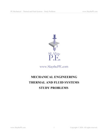
Percent compression, as seen in Fig. 2, is a means fordetermining the compression ratio of a particularconnector/conductor assembly. Achieving higher percentcompression is critical in creating residual radial forcesnecessary for establishing and maintaining low contactresistance between the connector tube and conductorsurface.II.SWAGE TECHNOLOGY SYSTEMUnlike conventional fixed die crimp systems, “SwageTechnology” incorporates a 360⁰ flexible die technologyas seen in Fig. 3. This flexible die applies the forcesgenerated from the hydraulic tool radially andsymmetrically around the connector tube as seen inFig. 4. This forces the material under the die to moveinwards radially to the axis of the connector tube. Asymmetrical swaging motion can produce as much astwice the area of reduction, or percent compression, asother fixed die compression systems. The swagingmotion also eliminates the losses created by movingmaterial tangentially to the connector tube as seen in thefixed die crimp in Fig. 4. The 360 flexible die providessymmetrical motion regardless of the initial positioningof the tube in the swaging tool. A comparison ofresulting connector cross sections from flex die andfixed die crimps are seen in Fig. 5.FIG. 2. PERCENT COMPRESSION CALCULATIONTypical SSC crimp connectors used for ACSR conductorare manufactured from tubes produced through extrusionor drawing process. These tubes have well establishedgeometric tolerances for the outside diameter, insidediameter, and wall thickness. Small variances in each ofthese three (3) parameters can lead to significantcompression ratio variances along the axis of theconnector tube.The need for repeatable and reproducible low contactresistance connection systems has never been morecritical then today. Increasing demands on power gridshas led to increased line temperatures and consequently,a higher number of both SSC and TSC connectorfailures. These facts were recently amplified in theUnited States Department of Energy’s (U.S. DOE) 2015quadrennial assessment report. The report characterizedcompression connectors for overhead lines as the weaklinks in the electricity delivery network, where powertransmission can be limited by the connector resistanceand disruptions can occur owing to mechanical failures[1]. Additionally, in a recent publication by AvistaUtilities, they acknowledged that 4% of all splices werein “very poor” condition heading towards failure with anadditional 25% of all installed splice classified asquestionable [2]. This reinforces the need for reliabletesting of SSC and TSC connectors which more closelyreflects stresses encountered during modern-day service.FIG. 3. 360 DEGREE SWAGE TECHNOLOGY FLEX DIESwage TechnologyFixed Die CrimpFIG. 4. 360 RADIAL FORCES APPLIED BY SWAGED DIE VS.VERTICAL FORCES APPLIED BY FIXED DIESwaged coreSwaged cond.Fixed die coreFixed die cond.FIG. 5. COMPARISON OF CROSS SECTIONS OF FLEX DIE ANDFIXED DIE COMPRESSION
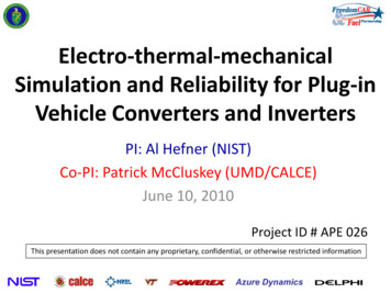
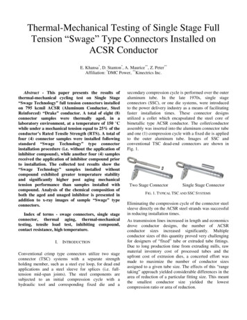
III.USE OF OXIDE INHIBITING COMPOUNDCompounds have been typically used for three (3)primary purposes: increasing mechanical holdingstrength, protection from corrosion and lowering contactresistance [3]. The performance of these three (3)parameters when installing Swage Technologyconnectors without inhibitor compound were evaluatedin previous testing as briefly described below.A. Mechanical Holding StrengthSwage Technology connectors incorporate a flaring andlocking design behind the swage area as seen in Fig. 6.This key design feature increases system sheer forceswhich lead to increased mechanical holding strength andeliminates the need to rely on the grit found in typicalinhibitors for increased mechanical strength. Maximumload tests were successfully performed on different sizesof ACSR connectors as per ANSI C119.4 without theuse of the inhibitor compound to verify their mechanicalstrength [4, 5, 6].FIG. 7. ANSI C119.4 CLASS “AA” TEMPERATURE GRAPH AT175⁰C RISE - CYCLES 500 TO 1000FIG. 6 FLARE OUT OF CONDUCTOR BEHIND SWAGED AREALONGITUDINAL SECTION IN SWAGED CONNECTORB. Corrosion ProtectionCorrosion Tests were performed in parallel on two (2)sets of Drake swaged connectors as per ASTM B1172007 for 1000 hours [7]. One (1) set was swaged withinhibitor compound present at the electrical interface andone (1) without inhibitor compound. The CorrosionTests simulated an accelerated aging process byexposing both sets of connectors to salt spray conditions.The final difference in measured contact resistancebetween samples from the two (2) sets was negligible[8].C. Contact Resistance PerformanceA Current Cycling Test as per ANSI C119.4 Class “AA”was performed on Swage Technology SSC connectorsinstalled on 2156 ACSR Bluebird. Five hundred (500)cycles were completed as per the standard and anadditional aging up to one thousand (1000) total cycleswas completed. Temperature and contact resistancemeasurements, as seen in Fig. 7 and Fig. 8, met ANSIC119.4 requirements [9].FIG. 8. ANSI C119.4 CLASS “AA” RESISTANCE GRAPH AT175⁰C RISE - CYCLES 500 TO 1000In order to investigate the effects of applying compoundin full tension applications, two test (2) assemblies wereestablished: one (1) assembly with inhibitor compoundand a second assembly without inhibitor compound. Adiscussion of the contrast in performances between thetwo (2) assemblies is presented later in this paper.Notable changes in performance of Swage Technologyconnectors under Thermal-Mechanical Testing will alsobe discussed.IV.THERMAL-MECHANICAL CYCLING TESTTraditional thermal cycle aging is performed under staticconditions as per ANSI C119.4. Recently, some testsbegan incorporating tension in thermal cycling to moreclosely emulate real line conditions.In September 2015, DMC initiated a research project toevaluate the performance of single stage swagedconnectors installed on ACSR conductor under tension
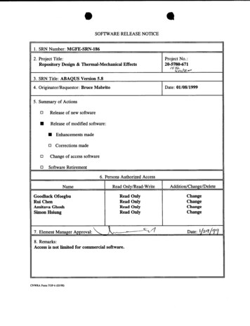
and high temperature operation at Kinectrics Inc. Theprimary purpose of this test was to study the mechanicaland electrical effects of repeated high temperaturecycling on connectors while under tension. A secondaryobjective was to compare the performance of the swageconnectors installed with and without oxide inhibitorcompound. A target temperature of 150 C measured onthe 795 kcmil ACSR conductor surface was chosen forthe study. Since no published industry standard currentlyexists for thermal cycling of overhead transmissionconnectors while under mechanical tension, generalprocedural guidelines were incorporated from CIGREGuide B426 to conduct this thermal-mechanical testing[10].A. TEST SETUPThe test setup consisted of two (2) assemblies each withtwo (2) single stage swaged full-tension joints (i.e.splices) and two (2) single stage swaged dead-endsinstalled on 795 kcmil Drake ACSR conductor. This isshown schematically in Fig. 9. One (1) assembly wasinstalled without the application of oxide inhibitorcompound between the electrical interface of connectorand conductor surface. The second assembly receivedthe application of inhibitor compound prior to connectorinstallation. The conductor on both assemblies was wirebrushed loosely in the contact area with the aluminumconnector sleeve. This was performed in order to removesurface oxidation or other surface contaminants prior toconnector installation. No other preparation of theconductor or connector was performed.FIG. 10. TYPICAL DEAD-END CONNECTOR INSTALLED FORTHERMAL-MECHANICAL TESTINGThe conductor used for this test was 795 kcmil, 26/7ACSR (Drake), consisting of twenty-six (26) roundaluminum strands and seven (7) regular strength, roundgalvanized strands. The conductor has a Rated TensileStrength (RTS) of 31,500 lb. Tension and temperaturedata collection was done automatically throughout eachcycle. DC resistance measurements for each connectorwere recorded every ten (10) cycles up to a total of onehundred (100) cycles and at twenty-five (25) cycleintervals until completion of the test. The contactresistance measurements were made across eachconnector entrance between equipotential points. Theequipotential point on the stranded conductor wascreated by twisting a pair of copper wire around thecircumference at a distance of 1 in from the connectorentrance (i.e. mouth). A bronze bolt screwed into thebody of each connector was used for the voltage dropmeasurements at the connector end.B. TEST PROTOCOLFIG. 9. SCHEMATIC OF TEST SPAN ASSEMBLIESThe assemblies were installed to form a spanapproximately 130 ft long. The two (2) assemblies wereelectrically connected in series and physically werelocated parallel to each other as shown in Fig. 6. Bothtest assemblies were instrumented with numerousthermocouples and a load cell to monitor sampletemperatures and tensions during the thermal-cyclingtest program. Thermocouples were drilled and peenedinto each connector at a distance of 2 in from their ends.This meant each splice had two (2) thermocouples andeach dead-end had one (1) thermocouple. The four (4)test connectors in each assembly were spaced such thatthe effective length of conductor between them wasapproximately the same. A dead-end connector installedfor testing is shown in Fig. 10.A thermal cycling test was designed and carried outunder controlled ambient conditions in Kinectrics’Mechanical Test Laboratory. The complete testconsisted of a total of 1,100 heating and cooling cycles.A single thermal cycle was completed by heating theconductor surface from ambient temperature to 150 Cby applying 1,150 A of AC current. This temperaturewas maintained for a period of two (2) hours (i.e.soaking period) before allowing the assemblies to coolby natural convection. A temperature plot for a typicalthermal-mechanical cycle is shown in Fig. 11. Bothassemblies were allowed to cool until the maximumthermocouple reading did not vary by more than 2 Cover a ten (10) minute period.
FIG. 11. TYPICAL TEMPERATURE AND TENSION DURINGTHERMAL CYCLEThe tension in each assembly was increased to 25% ofthe conductor’s RTS while at ambient temperature. Thisload was allowed to decrease during the heating cyclesas demonstrated in Fig. 11. Since some creep was takenout from the conductor during the test and due to slightvariation of ambient temperature during the curse of thetest program, the maximum tension measured at ambienttemperature was monitored and adjusted within 2% RTSthroughout the test.FIG. 13. TEMPERATURES OF SPLICES WITH INHIBITORC. TEST DATAThe temperature measured by the thermocouples at theend of the two (2) hour soaking period at 150 C wasrecorded as the steady state temperature for eachrespective electrical connection. The steady statetemperatures measured on all connectors (wi
A Current Cycling Test as per ANSI C119.4 Class “AA” was performed on Swage Technology SSC connectors installed on 2156 ACSR Bluebird. Five hundred (500) cycles were completed as per the standard and an additional aging up to one thousand (1000) total cycles was completed. Temperature and contact resistance measurements, as seen in Fig. 7 and Fig. 8, met ANSI C119.4 requirements