Transcription
MECHANICAL INTEGRITYTESTING (MIT)EPA Region 6Brian Graves(214) 665-7193graves.brian@epa.gov(Credits to George Robin, Steve Platt & Chuck Tinsley)
USDWs(Underground Sources ofDrinking Water)Pronounced:
Mechanical Integrity(MI)Part 1Internal Mechanical Integrity40 CFR §146.8(a)(1)Part 2External Mechanical Integrity40 CFR §146.8(a)(2)
146.8 Mechanical integrity.(a) An injection well has mechanical integrity if:(Internal)(1) There is no significant leak in the casing, tubing or packer;(b) One of the following methods must be used to evaluate theabsence of significant leaks under paragraph (a)(1) of this section:(1) Following an initial pressure test, monitoring of the tubingcasing annulus pressure with sufficient frequency to berepresentative, as determined by the Director, whilemaintaining an annulus pressure different from atmosphericpressure measured at the surface;(2) Pressure test with liquid or gas; or
(3) Records of monitoring showing the absence of significantchanges in the relationship between injection pressure andinjection flow rate for the following Class II enhanced recoverywells:(i) Existing wells completed without a packer provided that apressure test has been performed and the data is available andprovided further that one pressure test shall be performed at atime when the well is shut down and if the running of such a testwill not cause further loss of significant amounts of oil or gas; or(ii) Existing wells constructed without a long string casing, butwith surface casing which terminates at the base of fresh waterprovided that local geological and hydrological features allow suchconstruction and provided further that the annular space shall bevisually inspected. For these wells, the Director shall prescribe amonitoring program which will verify the absence of significantfluid movement from the injection zone into an USDW.
(External)(a)(2) There is no significant fluid movement into an undergroundsource of drinking water through vertical channels adjacent to theinjection well bore.c) One of the following methods must be used to determine theabsence of significant fluid movement under paragraph (a)(2) ofthis section:(1) The results of a temperature or noise log; or(2) For Class II only, cementing records demonstrating thepresence of adequate cement to prevent such migration; or(3) For Class III wells where the nature of the casing precludes theuse of the logging techniques prescribed at paragraph (c)(1) of thissection, cementing records demonstrating the presence ofadequate cement to prevent such migration;
4) For Class III wells where the Director elects to rely oncementing records to demonstrate the absence of significantfluid movement, the monitoring program prescribed by§146.33(b) shall be designed to verify the absence of significantfluid movement.(Alternative tests)(d) The Director may allow the use of a test to demonstratemechanical integrity other than those listed in paragraphs (b)and (c)(2) of this section with the written approval of theAdministrator. To obtain approval, the Director shall submit awritten request to the Administrator, which shall set forth theproposed test and all technical data supporting its use. TheAdministrator shall approve the request if it will reliablydemonstrate the mechanical integrity of wells for which its use isproposed. Any alternate method approved by the Administratorshall be published in the FEDERAL REGISTER and may be used inall States unless its use is restricted at the time of approval bythe Administrator.
(e) In conducting and evaluating the tests enumerated in thissection or others to be allowed by the Director, the owner oroperator and the Director shall apply methods and standardsgenerally accepted in the industry. When the owner or operatorreports the results of mechanical integrity tests to the Director,he shall include a description of the test(s) and the method(s)used. In making his/her evaluation, the Director shall reviewmonitoring and other test data submitted since the previousevaluation.(f) The Director may require additional or alternative tests if theresults presented by the owner or operator under §146.8(e) arenot satisfactory to the Director to demonstrate that there is nomovement of fluid into or between USDWs resulting from theinjection activity.
What are our main MI concerns?1 Any leaks in the system?
What are our main MI concerns?1 Any leaks in the system?2 Is injected fluid entering andremaining in the approved interval?
What are our main MI concerns?1 Any leaks in the system?2 Is injected fluid entering andremaining in the approved interval?3 Is there crossflow of fluid intoUSDWs?
What are our main MI goals?1 Any leaks in the system?(Internal MI)Goal:Prevention of leakage through the“walls” of the well (casing, tubing, etc.)
Prevention of Leakage through the“walls” of the well (casing, tubing, etc.)How leakage can be discovered: pressure tests.
INTERNAL MI ANNULUS PRESSURE TEST Tests the tubing, casing and packer for leaks. Testing requirements vary by well Class and UICprogram requirements. These vary by State or Tribe. Typically the casing/tubing annulus is pressured tothe maximum allowable injection pressure to ensurethe casing can withstand this pressure should thetubing or packer fail. Director variances can also beallowed. The test length is typically 30 minutes to 1 hour. Test failure is typically a pressure loss of 5 – 10%
Prevention of Leakage through the“walls” of the well (casing, tubing,etc.).How leakage can be discovered: pressure tests downhole logging (discussed later)
Prevention of Leakage through the“walls” of the well (casing, tubing, etc.)How leakage can be discovered: pressure tests downhole logging monitoring of injection activities.– Annulus pressure– Injection pressure/rate relationship.
What are our main MI Goals?Prevention of Fluid Movement throughCasing/Wellbore Annular Space2 Is injected fluid entering andremaining in the approved interval?(External MI)
What are our main MI Goals?Prevention of Fluid Movement throughCasing/Wellbore Annular Space2 Is injected fluid entering andremaining in the approved interval?(External MI)3 Is there crossflow of fluid intoUSDWs?(External MI)
What are our main MI Goals?Prevention of Fluid Movement throughCasing/Wellbore Annular SpaceProper cementing and construction
CasingCementingOperations
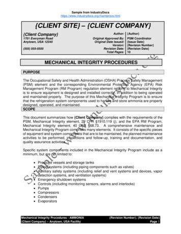
Two-stage Cementing Tools:(Float Collar, DV tool, and Plugs)
Float Collar near TDDV tool @ 4000 ft3rd- Closing Plug(Closes DV tool)2nd - Opening Plug(Opens DV tool)1st - Shut-off Plug(Ends first stage)
Centralizers
CementBondLog(CBL)
Cement needs to set properly before acement integrity log is run. This can take from10 to 50 hours for typical cement jobs. Full compressive strength is reached in 7 to10 days. The setting time depends on the typeof cement, temperature, pressure, and the useof setting accelerants. Excess pressure on the casing should beavoided during the curing period so that thecement bond to the pipe is not disturbed.
Cement bond logs were run as early as 1958 withearly sonic logs and the temperature log was usedto find the cement top beginning in 1933. Cement integrity logs are run to determine thequality of the cement bond to the casing, toevaluate cement fill-up between the casing and thewellbore rock and to evaluate the cement bond tothe wellbore rock. A poor cement bond may allow unwanted fluids toenter the wellbore or injected fluid to leave theinjection interval.
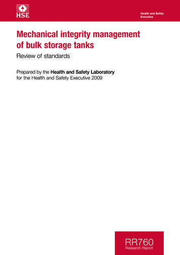
Identification of important features on a variable-density log(VDL) (courtesy of Baker Atlas).
Typical cement-bond log presentation (courtesy of Baker Atlas).
In cases of poor bonding,casing-collar signals mayalso be identified as "w"patterns (anomalies)
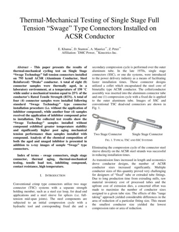
Field example showing microannulus effect on amplitudeand VDL log displays (courtesy of Baker Atlas).Pressuring the casing improves the acoustic coupling tothe formation and the casing signal will decrease and theformation signal will become more obvious
CEMENTEVALUATIONTOOL(CET)
CETPURPOSE SAME AS CEMENT BOND LOG (CBL)ONLY MORE ADVANCED PRINCIPLE INVESTIGATES CEMENT RADIALLY MEASURES CASING DIAMETER, CASINGROUNDNESS, AND TOOL ECCENTERING
CETPRINCIPLE OF OPERATION ULTRA SONIC ENERGY MAKES CASINGRESONATE RATE OF DAMPENING IS MEASURED RADIAL INVESTIGATION IS ACHIEVEDWITH 9 TRANSDUCERS
CETFACTORS AFFECTING MEASUREMENT TYPE OF FLUID IN WELL THICKNESS OF CASING WALL AMOUNT OF CEMENT BONDED TOCASING COMPRESSIVE STRENGTH OF CEMENT
CETEQUIPMENT 8 TRANSDUCERS IN HELICAL PATTERN 1 TRANSDUCER (MEASURES FLUIDSOUND VELOCITY) TOOL SIZE 3-3/8 inches to 4 inches
CETPROCEDURE REMOVE TUBING ENSURE TOOL IS CENTRALIZED LOG ONLY IN LIQUID FILLED CASING RUN WITH CASING COLLAR LOCATORAND GAMMA RAY
CETADVANTAGES RADIAL CEMENT EVALUATION CEMENT CHANNEL IDENTIFICATION IMMUNE TO MICROANNULUS NOT AFFECTED BY “FAST FORMATIONS” “EASIER” TO INTERPRET
A GOODMANUALTO HAVEONHAND
RADIOACTIVE TRACERSURVEYS(RATS)
RADIOACTIVE TRACERSURVEY PURPOSE FLOW PROFILING (volumetric) DETERMINE FLUID MIGRATION BOTTOMHOLE CEMENT CHANNELS(Time Drive) CASING, TUBING, PACKER LEAKS(Internal MI)(Slug Chase)
RATSOPERATION PRINCIPLES USE RADIOACTIVE IODINE (1/2 life 8 days) EJECT TRACER @ surface or downhole FOLLOW TRACER as it travels USE GAMMA RAY TOOL as detector DETECT MIGRATION OF TRACER through tubingand/or casing
RATS EQUIPMENT Radioactive material EJECTORSurface or downhole 2 or more Gamma Ray DETECTORS Ejector/Detector CONFIGURATION variesdepending on objective Tool DIAMETER as small as 1-1/2 inches
RATS PROCEDURE LOAD TRACER at surface RUN tool in tubing or casing RUN BASE LOG with well on injection EJECT tracer at or near surface if running in casing EJECT tracer above the packer if in tubing FOLLOW tracer to injection zone, while checking for leaks LOG ABOVE PERFORATIONS/SCREEN for channels outside casing Can check FLOW PROFILE with Spinner Run with CASING COLLAR LOCATOR
FACTORS AFFECTINGGAMMA-RAY MEASUREMENT RADIOACTIVE (HOT) formations INJECTION RATE Ejector/Detector CONFIGURATION PIPE SCALE
SlugChase
RAT tool typically starts here
TIMEDRIVES
RAT tool set here
Leak detected bylower detectorLeak detected byupper detector
Flow Profiles
TEMPERATURESURVEYS(External MI)
TEMPERATURE SURVEYS Oldest of the Production SurveyingInstruments (mid 1930s) Mercury/piston Vapor pressure/bourdon type element(Bottomhole temperature measurements) Thermistor – platinum element – resolvestemperature changes of 0.05 deg F» Analog Logging Units» Digital Logging Units
TEMPERATURE SURVEYPURPOSE LOCATE CEMENT TOPS AFTER PRIMARYCEMENTING (HEAT FROM EXOTHERMICREACTION) FLUID MIGRATION DETERMINATION CASING SHOE BEHIND PIPE TUBING, CASING, PACKER LEAKS INTERFORMATIONAL FLUID FLOW FLOW (VOLUMETRIC) PROFILING (RARE) IDENTIFICATION OF INTERVALS PRODUCINGGAS (COOLING EFFECT FROM EXPANSION)
TEMPERATURE SURVEYOPERATION PRINCIPLE DOWNHOLE TEMPERATURE GOVERNED BYGEOTHERMAL GRADIENT INJECTION OF FLUID WITH LARGETEMPERATURE DIFFERENCE (FROM GRADIENT) ZONES (OR LEAKS) TAKING INJECTED FLUIDSWILL RETURN TO GEOTHERMAL GRADIENT AT ASLOWER RATE
Since cement gives off heatas it cures, the temperaturelog was used to provideevidence that the well wasactually cemented to a levelthat met expectations. Anexample is shown at right. The top of cement is locatedwhere the temperaturereturns to geothermalgradient. The log must be run duringthe cement curing period asthe temperature anomaly willfade with time.
TEMP SURVEY – A BASIC PROCEDURE LET WELL STAND IDLE AT LEAST 24 HOURS RUN “BASE LOG” – GEOTHERMAL GRADIENT ENSURE INJECTION FLUID TEMPERATURE ISSIGNIFICANTLY DIFFERENT FROM BOTTOMHOLE TEMPERATURE START INJECTION WHILE LOGGING HOLE(OPTIONAL) SHUT-IN AFTER PREDETERMINED VOLUME ISINJECTED LOG HOLE AFTER 0, 12, AND 24 HOURS SHUT-IN
NOISE LOG(External MI)
NOISE LOG PURPOSE TO “HEAR” FLUID FLOWOCCURRING INSIDE OR OUTSIDEWELL TUBULARS BEHIND CASING CHANNELS (waterflow pressure drop OR gas thru liquid) TUBING AND/OR CASING LEAKS
NOISE LOGOPERATION PRINCIPLES FLUID TURBULENCE (FLOW) - - - NOISE NOISE OCCURS OVER A RANGE OFFREQUENCIES - - TYPICAL TO THE KINDOF FLOW CREATED– GAS flow upward thru liquid»Flows in “bubbles” which “ring”
NOISE LOGOPERATION PRINCIPLES FLUID TURBULENCE (FLOW) - - - NOISE NOISE OCCURS OVER A RANGE OFFREQUENCIES - - TYPICAL TO THE KINDOF FLOW CREATED– FLUID turbulence when forcedacross constriction – pressuredrop
NOISE LOGOPERATION PRINCIPLES FLUID TURBULENCE (FLOW) - - - NOISE NOISE OCCURS OVER A RANGE OFFREQUENCIES - - TYPICAL TO THE KIND OFFLOW CREATED 200 Hz (cycles per second) 600 Hz 1000 Hz 2000 Hz
NOISE LOGEQUIPMENT TRANSDUCER (converts sound toelectrical signal - to be amplified) FREQUENCY SEPARATING FILTERS SPEAKER (esp. headphones for operator) TYPICAL SIZE 1¾ inch X 3½ feet (assmall as 1 inch O.D.)
NOISE LOGCHARACTERISTICSESSENTIAL TO INTERPRETATION LOUDNESS - measured levels above ambient.amplitude. on all 4 frequencies- severity of the problem CHARACTER – variation in level on a particularcut from station to station is related to the path offlow- how flow is taking place PITCH – frequency content of sound at a peak innoise level- type of flow (single phase or gas thru liquid)
NOISE LOGOPERATION GUIDELINES Logging Sonde takes readings at different depths whileSTATIONARY. Log can be utilized in virtually any DOWNHOLE CONDITION(liquid or gas filled). APPLY CRITERIA
NOISE LOGOPERATION CRITERIA Operator consults CONSTRUCTION DETAILS WELL SHUT-IN (for behind-pipe flow) Record Noise Levels at the 4 FREQUENCIES(200Hz, 600Hz, 1000Hz, 2000Hz) MINIMUM READINGS taken opposite the ConfiningLayer, Base of USDWs and Well Con
146.8 Mechanical integrity. (a) An injection well has mechanical integrity if: (Internal) (1) There is no significant leak in the casing, tubing or packer; (b) One of the following methods must be used to evaluate the absence of significant leaks under paragraph (a)(1) of this section: (1) Following an initial pressure test, monitoring of the tubing-