Transcription
Installation InstructionsOriginal InstructionsKinetix 5500 Servo DrivesCatalog Numbers 2198-H003-ERS, 2198-H008-ERS, 2198-H015-ERS, 2198-H025-ERS, 2198-H040-ERS, 2198-H070-ERS,2198-H003-ERS2, 2198-H008-ERS2, 2198-H015-ERS2, 2198-H025-ERS2, 2198-H040-ERS2, 2198-H070-ERS2TopicPageSummary of Changes1About the Kinetix 5500 Drives1Catalog Number Explanation2Before You Begin2Remove the Grounding Screws in Ungrounded Power Configurations2Install the Kinetix 5500 Servo Drive3Connector Data6Wiring Requirements9Attach the Motor Cable Shield Clamp10Circuit Breaker/Fuse Selection12Motor Overload Protection14Additional Resources15Summary of ChangesThis publication contains new and updated information as indicated in the following table.TopicPageAdded ‘impedance grounded’ when ever ungrounded and corner-grounded power configurations are mentioned2 3Updated callouts in Grounding Screw figure and updated text in Grounding Screw table3Added 2198-Hxxx-ERS2 safety connector view and shared-bus wiring connectors to Features and Indicators figure6Updated Wiring Requirements table with text and values9Added Circuit Breaker/Fuse Selection tables12 14Updated text in Motor Overload Protection with new thermal retention feature in drive firmware 4.001 or later14About the Kinetix 5500 DrivesKinetix 5500 servo drives provide an Integrated Motion over the EtherNet/IP network solution for applications with output power and currentrequirements in the range of 0.2 14.6 kW and 1.4 32.5 A 0-pk, respectively.See the Kinetix 5500 Servo Drives User Manual, publication 2198-UM001, for detailed information on wiring, applying power, troubleshooting,and integration with ControlLogix 5570, ControlLogix 5580, and GuardLogix 5570, or CompactLogix 5370 and Compact GuardLogix 5370controllers.
Kinetix 5500 Servo DrivesCatalog Number ExplanationThis publication applies to the following Kinetix 5500 servo drives. For connecting safe torque-off signals, hardwired drives use the safe torque-off(STO) connector and ship with the protective cover removed. Integrated safe torque-off drives do not use the STO connector and ship with theprotective cover in place. See Connector Data on page 6 to locate the cover.Kinetix 5500 Drive Catalog NumbersDrive Cat. No.(hardwired STO)Drive Cat. No.(integrated STO)2198-H003-ERS2198-H003-ERS2Frame SizeInput VoltageContinuousOutput PowerkWContinuousOutput CurrentA 0-pk0.2 kW0.3 kW0.6 kW1.40.5 kW0.8 kW1.6 kW3.51.0 kW1.5 KW3.2 kW7.12.4 kW5.1 kW11.34.0 kW8.3 kW18.47.0 kW14.6 S2198-H040-ERS22198-H070-ERS2198-H070-ERS2195 264V rms, single-phase195 264V rms, three-phase324 528V rms, three-phase2195 264V rms, three-phase324 528V rms, three-phase3Before You BeginRemove all packing material, wedges, and braces from within and around the components. After unpacking, check the item nameplate catalognumber against the purchase order.The Kinetix 5500 servo drives ship with the following: Wiring plug connector set for mains input power (IPD), 24V control input power (CP), digital inputs (IOD), motor power (MP), motorbrake (BC), and safe torque-off (STO) 2198-KITCON-DSL connector kit for motor feedback connections Wiring plug connector for shunt power (RC) connections that is installed on the drive These installation instructions, publication 2198-IN001TIPReplacement connector sets are also available. See the Kinetix Servo Drives Specifications Technical Data, publication GMC-TD003, for more information.Remove the Grounding Screws in Ungrounded Power ConfigurationsRemove the grounding screws only when using ungrounded, corner-grounded, or impedance-grounded power configurations. Removing the screwsinvolves gaining access, opening the side door, and removing the screws.IMPORTANTIf you have grounded wye power distribution, you do not need to remove the screws. Go to Install the Kinetix 5500 Servo Drive on page 3.Removing the grounding screws can affect EMC performance.Removing the grounding screws in multi-axis configurations is best done when the drive is removed from the panel and placed on its side on a solidsurface that is equipped as a grounded static-safe workstation.ATTENTION: Because the unit no longer maintains line-to-neutral voltage protection, the risk of equipment damage exists when you remove the groundingscrews.2Rockwell Automation Publication 2198-IN001D-EN-P - February 2016
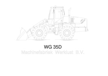
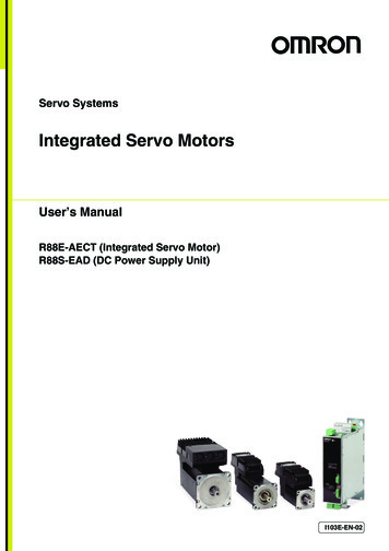
Kinetix 5500 Servo DrivesATTENTION: To avoid personal injury, the grounding screws access door must be kept closed when power is applied. If power was present and then removed,wait at least 5 minutes for the DC-bus voltage to dissipate and verify that no DC-bus voltage exists before accessing the grounding screws.Remove the Grounding ScrewsGrounding ScrewAccess DoorAC ScrewDC ScrewKinetix 5500 Drive(side view)Lift door to meetarrow at left.Grounding screws are installed for grounded power configurations(screws installed is default setting). Remove both screws for ungrounded, corner-grounded, andimpedance-grounded power for three-phase operation Remove only the AC screw for single-phase operationATTENTION: Risk of equipment damage exists. The drive ground configuration must be accurately determined. Leave the grounding screws installed forgrounded power configurations (default). Remove the screws for ungrounded, ungrounded, corner-grounded, and impedance-grounded power.Grounding Screw ConfigurationsGround Configuration (1)Grounding Screw ConfigurationBenefits of ConfigurationGrounded (wye)Both screws installed (default setting) AC fed ungrounded Corner grounded Impedance groundedBoth screws removed Helps avoid severe equipment damage when ground faults occurs Reduced leakage currentSingle-phase input powerAC screw removed (2)Minimizes leakage current for single-phase operationUL and EMC complianceReduced electrical noiseMost stable operationReduced voltage stress on components and motor bearings(1) Refer to the Kinetix 5500 Servo Drives User Manual, publication 2198-UM001, for example configurations.(2) Removing the AC grounding screw to minimize leakage current in single-phase operation can affect EMC performance.Install the Kinetix 5500 Servo DriveThese procedures assume that you have prepared your panel and understand how to bond your system. For installation instructions regardingequipment and accessories not included here, refer to the instructions that came with those products.SHOCK HAZARD: To avoid hazard of electrical shock, perform all mounting and wiring of the Kinetix 5500 drive prior to applying power. Once power is applied,connector terminals can have voltage present even when not in use.ATTENTION: Plan the installation of your system so that you can perform all cutting, drilling, tapping, and welding with the system removed from the enclosure.Because the system is of the open type construction, be careful to keep any metal debris from falling into it. Metal debris or other foreign matter can becomelodged in the circuitry and result in damage to components.Rockwell Automation Publication 2198-IN001D-EN-P - February 20163
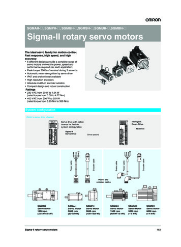
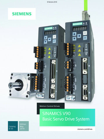
Kinetix 5500 Servo DrivesMount the Kinetix 5500 DriveFollow these steps to mount the drive in single-axis configurations.1. Observe these clearance requirements when mounting a single drive to the panel: Additional clearance is required for cables and wires or the shared-bus connection system connected to the top of the drive. Additional clearance is required if other devices are installed above and/or below the drive and have clearance requirements of theirown. Additional clearance left and right of the drive is required when mounted adjacent to noise sensitive equipment or clean wire ways. The recommended minimum cabinet depth is 300 mm (11.81 in.).40 mm (1.57 in.) clearance abovedrive for airflow and installation.Kinetix 5500Servo DriveClearance left of thedrive is not required.Clearance right of thedrive is not required.40 mm (1.57 in.) clearance belowdrive for airflow and installation.Refer to the Kinetix Servo Drives Technical Data, publication GMC-TD003, for Kinetix 5500 drive dimensions.IMPORTANTMount the drive in an upright position as shown. Do not mount the drive on its side.In multi-axis shared-bus configurations, drives must be spaced by aligning the zero-stack tab and cutout. For mounting, sizing, andconfiguring shared-bus configurations, refer to the Kinetix 5500 Servo Drives User Manual, publication 2198-UM001.Bus-bar system used in bus-sharingconfigurations is not shown for clarity.Zero-stack Tab andCutout Aligned2. Mount the Kinetix 5500 drive to the cabinet subpanel with M4 (#8-32) steel machine screws torqued to 2.0 N m (17.7 lb in), max.4Rockwell Automation Publication 2198-IN001D-EN-P - February 2016
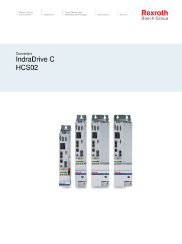
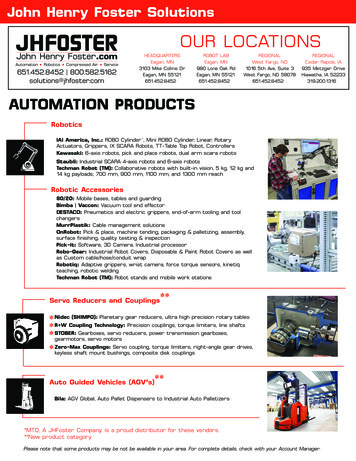
Kinetix 5500 Servo DrivesProduct DimensionsIncluded in this figure are the drill hole patterns for standalone drives. Refer to the Kinetix 5500 Servo Drives User Manual, publication2198-UM001, for multi-axis drill-hole patterns.Kinetix 5500 Drives with 2198-KITCON-DSL Connector KitDimensions are in mm (in.)Ø M4 (#8-32)FG34.00(1.34)EB2198-H003-ERSDrive is ShownApplies toOnlyFrame 30.052.50(2.07)0.0C3.0(0.12)ADDrill Hole PatternsKinetix 5500 DriveCat. No.FrameAmm (in.)Bmm (in.)150 (1.97)170 (6.69)255 (2.16)385.2 (3.35)Cmm (in.)Dmm (in.)Emm (in.)Fmm (in.)Gmm (in.)215 (8.46)193.68 (7.62)4.51 (0.18)225 (8.86)265 (10.43)243.84 (9.60)5.00 (0.20)250 (9.84)294 (11.57)273.70 Sx200 (7.87)2198-H025-ERSx226 (8.90)2198-H040-ERSx2198-H070-ERSxKinetix 5500 Drives with 2198-H2DCK Converter KitDimensions are in mm (in.)Frame 1 Servo ack Converter KitMounted on Frame 1 Drive256(10.08)256(10.08)2198-H2DCKFeedback Converter KitMounted on Frame 2 Drive56.0(2.20)256(10.08)2198-H2DCKFeedback Converter KitMounted on Frame 3 DriveRefer to Kinetix Servo Drives Technical Data, publication GMC-TD003, for motor/actuator compatibility with the 2198-H2DCK converter kitand product dimensions.Rockwell Automation Publication 2198-IN001D-EN-P - February 20165
Kinetix 5500 Servo DrivesConnector DataUse this illustration to identify the Kinetix 5500 drive features and indicators.Kinetix 5500 Drive Features and Indicators778171Kinetix 5500 Drive, Front View(2198-H003-ERSx drive)29Kinetix 5500 Drive, Top View(2198-H003-ERS drive)10116L3125Shared-bus AC InputWiring ConnectorL113U V14W–1231920152121212418L2Shared-bus 24V InputWiring ConnectorProtectiveKnock-outKinetix 5500 Drive, Top View(2198-Hxxx-ERS2 drive)116ItemDescription1Motor cable shield clamp(1)ItemDescription8Module status indicator15Motor brake (BC) connector2Converter kit mounting hole (under cover)9Network status indicator16Ground terminal3Motor feedback (MF) connector10LCD display17Shunt resistor (RC) connector4Digital inputs (IOD) connector11Navigation push buttons18AC mains input power (IPD) connector5Ethernet (PORT1) RJ45 connector12Link speed status indicators19DC bus (DC) connector (under cover) (2)6Ethernet (PORT2) RJ45 connector13Link/Activity status indicators2024V control input power (CP) connector21Safe torque-off (STO) connector (3)(applies to only 2198-Hxxx-ERS drives)7Zero-stack mounting tab/cutout14Motor power (MP) connector(1) Protective knock-out covers the 2198-H2DCK converter kit mounting hole. Remove knock-out for use with the converter kit.(2) DC bus connector ships with protective knock-out cover that can be removed for use in shared-bus configurations.(3) Protective knock-out cover is removed on 2198-Hxxx-ERS (hardwired STO) drives.Kinetix 5500 Drive orIPDAC mains input power4-position plug, terminal screwsDCDC common bus power2-position (T-connector used in shared-bus configurations)CP24V control input power2-position plug, terminal screwsRCShunt power2-position plug, terminal screwsMPMotor power4-position plug, terminal screwsMFMotor feedback2-position plug, spring terminalsBCBrake power2-position plug, terminal screwsIODDigital inputs4-position plug, spring terminalsSTOSafe torque off5-position plugs, spring terminals, 2x (2 rows of 5 pins)PORT1, PORT2Ethernet communication portsRJ45 EthernetRockwell Automation Publication 2198-IN001D-EN-P - February 2016
Kinetix 5500 Servo DrivesMains Input Power (IPD) ConnectorIPD PinDescriptionSignalChassis groundL3L2L3L3L2L1L2Three-phase input powerL1L1Shunt Power (RC) Connector PinoutRC PinDescriptionSignal1DC Shunt connections (frames 2 and 3)SH1SH122Shunt connections (frame 1)2DC DC Bus (DC) Connector PinoutDC PinDescriptionSignal1DCDC bus connections2DC Control Input Power (CP) Connector PinoutDescriptionSignal124V power supply, customer-supplied24V 224V common24V-12CP PinMotor Power (MP) Connector PinoutMP PinDescriptionUVThree-phase motor powerWSignalColorUBrownVBlackWBlueChassis groundUVWGreenMotor Feedback (MF) Connector PinoutMF Pin (1)DescriptionSignal1D Bidirectional data and power for digital encoder interface2D-Pin 1Pin 2Cable shield and grounding plate (internal to 2198-KITCON-DSL connector kit) termination pointSHIELDSHIELDCable shield and shield clamp (internal to 2198-H2DCK converter kit) termination point(1) Refer to Kinetix 5500 Servo Drives User Manual, publication 2198-UM001, for installation instructions.Rockwell Automation Publication 2198-IN001D-EN-P - February 20167
Kinetix 5500 Servo DrivesMotor Brake (BC) Connector PinoutBC PinDescriptionSignal1MBRK Motor brake connections2MBRK-21Digital Inputs (IOD) Connector PinoutIOD PinDescriptionSignal124V current-sinking fast input #1.This is a dual-function input.IN1 (1)2I/O common for customer-supplied 24V supply.COM324V current-sinking fast input #2.IN24I/O cable shield termination point.SHLDPin 1(1) This signal has dual-functionality. You can use IN1 (IOD-1) as registration or Home input.Safe Torque Off (STO) Connector PinoutSTO PinDescriptionSignal1Safety bypass plus signal. Connect to both safety inputs to disable the STO function.SB 2Safety bypass minus signal. Connect to safety common to disable the STO function.SB-3STO input 1 (SS IN CH0).S14STO input common (SCOM).SC5STO input 2 (SS IN CH1).S2IMPORTANTPin 1The safe torque-off (STO) connector applies to only the 2198-Hxxx-ERS drives.The 2198-Hxxx-ERS drives ship with the safe torque-off function enabled. Connect the safe torque-off inputs to a safety circuit or install bypasswiring to enable motion. Refer to the Kinetix 5500 Servo Drives User Manual, publication 2198-UM001, for more information.Ethernet Communication PORT1 and PORT2 Pinout8Port PinDescriptionSignal1Transmit port ( ) data terminalTD 2Transmit port (-) data terminalTD-3Receive port ( ) data terminalRD 4––5––6Receive port (-) data terminalRD-7––8––Standard RJ4518Rockwell Automation Publication 2198-IN001D-EN-P - February 2016
Kinetix 5500 Servo DrivesWiring RequirementsWire must be copper with 75 C (167 F) minimum rating. Phasing of mains AC power is arbitrary and earth ground connection is required forsafe and proper operation.IMPORTANTThe National Electrical Code and local electrical codes take precedence over the values and methods provided.Kinetix 5500 Drive Power and I/O Wiring RequirementsKinetix 5500 DriveCat. H025-ERSx2198-H040-ERSxConnects to TerminalsDescriptionMains input (1) power(single-axis IPD x2198-H025-ERSx2198-H040-ERSxMotor SxWire Sizemm2 (AWG)Strip Lengthmm (in.)Torque ValueN m (lb in)1.5 4(16 12)7.0 (0.28)1.5 6(16 10)10.0 (0.39)Motor power cable depends onmotor/drive combination.0.75 2.5 (4)(18 14)8.0 (0.31)0.5 0.6(4.4 5.3)2.5 6 (4)(14 10)10.0 (0.39)0.5 0.8(4.4 7.1)7.0 (0.28)0.22 0.25(1.9 2.2)0.5 0.6(4.4 5.3)PELV/SELV24V power(single-axis CP connector)CP-1CP-2Brake powerBC-1BC-2MBRK MBRK-N/A (5)DC Bus powerDC-1DC-2DC DC-N/A (6)N/A (6)N/A (6)Shunt power(frames 2 and 3)RC-1RC-2DC SHRC-1RC-2SHDC 0.5 4.0(20 12)8.0 (0.31)Shunt power(frame 1)0.5 0.6(4.4 5.3)ST0-1ST0-2ST0-3ST0-4ST0-5SB SBS1SCS20.2 1.5(24 16)10.0 (0.39)N/A (7)IOD-1IOD-2IOD-3IOD-4IN1 (3)COMIN2SHLD0.2 1.5(24 16)10.0 (0.39)N/A (7)Safety(2)Digital inputs24V 24V-2.5 0.5(14 20)(1) The wire size, strip length, and torque specifications shown here apply to the single-axis connector that ships with the drive. For the shared-bus connector specifications, refer to the Kinetix 5500 Servo Drives User Manual,publication 2198-UM001.(2) These signals and the safe torque-off (STO) connector apply to only the 2198-Hxxx-ERS drives.(3) This signal has dual-functionality. You can use IN1 (IOD-1) as registration or Home input.(4) Building your own cables or using third-party cables is not an option. Use single motor cable catalog number 2090-CSxM1DF-xxAAxx. Refer to the Kinetix Motion Accessories Specifications Technical Data, publication KNX-TD004,for cable specifications.(5) Motor brake wires are part of the 2090-CSBM1DF/DG motor cable.(6) DC bus connections are always made from drive-to-drive over the bus bar connection system. These terminals do not receive discrete wires.(7) This connector uses spring tension to hold wires in place.ATTENTION: To avoid personal injury and/or equipment damage, observe the following: Make sure installation complies with specifications regarding wire types, conductor sizes, branch circuit protection, and disconnect devices. The NationalElectrical Code (NEC) and local codes outline provisions for safely installing electrical equipment. Use motor power connectors only for connection purposes. Do not use them to turn the unit on and off. Ground shielded power cables to prevent potentially high voltages on the shield.Rockwell Automation Publication 2198-IN001D-EN-P - February 20169
Kinetix 5500 Servo DrivesAttach the Motor Cable Shield ClampA shield clamp and two screws are supplied with each Kinetix 5500 drive. Use the clamp to bond the motor cable shield-braid to chassis ground.IMPORTANT Loosen the retention screw, if needed, until you can start threading both clamp screws with the cable shield under the clamp. Make sure the cable clamp tightens around the cable shield and provides a good bond between the cable shield and the drive chassis.Kinetix VP Servo MotorsThese examples illustrate 2090-CSxM1DF/DG motor cables with connections to Kinetix VP motors and using 2198-KITCON-DSL feedbackconnector kits. If your motor connections are coming from other compatible Allen-Bradley servo motors/actuators, see Other Allen-BradleyMotors and Actuators on page 11.Cable Shield Clamp InstallationKinetix 5500 Servo Drives,Frame 1 or 2, Front View(frame 1 is shown)Motor Power(MP) Connector2198-KITCON-DSLMotor FeedbackConnector KitMotor Brake(BC) ConnectorClamp features applyto all frame sizes.Exposed shield braidunder clamp.Motor CableShield ClampShield Clamp Screws (2)2.0 N m (17.7 lb in), maxFeedback cable routedaround the shield clamp.IMPORTANTKinetix 5500 Servo Drives,Frame 2 or 3, Front View(frame 2 is shown)2198-KITCON-DSLMotor FeedbackConnector Kit2090-CSBM1DF-18AAxxSingle Motor CableServo DriveRetention Screw(loosen, do not remove)When the drive/motor combination calls for 18 AWG cable, the feedback cable routesaround the motor cable shield clamp.Servo DriveMotor Power(MP) ConnectorMotor Brake(BC) ConnectorShield ClampRetention ScrewFeedback cable routedwithin the shield braid.Motor CableShield ClampExposed shield braidunder clamp.Shield Clamp Screws (2)2090-CSBM1DF-14AAxxSingle Motor CableIMPORTANT10When the drive/motor combination calls for 14 or 10 AWG cable, the feedback cableroutes along with the power and brake wiring.Rockwell Automation Publication 2198-IN001D-EN-P - February 2016
Kinetix 5500 Servo DrivesOther Allen-Bradley Motors and ActuatorsThe other compatible Allen-Bradley motors and actuators require the 2198-H2DCK converter kit for wiring motor feedback. A clamp spacer isincluded with the kit for motor power/brake cable diameters that are too small for a tight fit within the drive clamp alone.IMPORTANTIf the power/brake cable shield has a loose fit inside the shield clamp, insert the clamp spacer between the shield clamp and the drive to reduce the clampdiameter. When the clamp screws are tight, 2.0 N m (17.7 lb in), the result must be a high-frequency bond between the cable shield and the drive chassis.Cable Clamp AttachmentService LoopsClamp CompressedAround Shield(no spacer required)Frame 1Servo DriveFrame 2Servo DriveFrame 3Servo DriveClamp Spacer Added(small diameter cable)Servo DriveClamp features apply toall frame sizes.Insert the clamp spacer whenthe cable diameter is smallerthan the drive clamp alone.Retention Screw(loosen, do not remove)Clamp Spacer(if needed)Shield ClampClamp Screws2.0 N m (17.7 lb in.)Refer to the Kinetix 5500 Servo Drives User Manual, publication 2198-UM001, for detailed information on wiring the 2198-H2DCK feedbackconverter kit and attaching the motor power/brake shield clamp.Rockwell Automation Publication 2198-IN001D-EN-P - February 201611
Kinetix 5500 Servo DrivesGround Your Kinetix 5500 Drive to the SubpanelGround Kinetix 5500 drives and 2198-CAPMOD-1300 capacitor modules to a bonded cabinet ground bus with a braided ground strap. Keep thebraided ground strap as short as possible for optimum bonding.Connecting the Braided Ground StrapKinetix 5500Servo Drive(standalone)Kinetix 5500Servo Drives(shared-bus)1234ItemDescription1Ground screw (green) 2.0 N m (17.5 lb in), max2Braided ground strap (customer supplied)3Ground grid or power distribution ground4Bonded cabinet ground bus (customer supplied)Refer to the System Design for Control of Electrical Noise Reference Manual, publication GMC-RM001, for more information.Circuit Breaker/Fuse SelectionThe Kinetix 5500 drives use internal solid-state motor short-circuit protection and, when protected by suitable branch circuit protection, are ratedfor use on a circuit capable of delivering up to 200,000 A (fuses) and 65,000 A (circuit breakers).Standalone Drive SystemsKinetix 5500 DrivesDrive Cat. No.UL ApplicationsIEC (non-UL) ApplicationsDrive Voltage, nomPhaseBussmann FusesCat. No.Molded Case CBCat. No.DIN gG FusesAmps (max)Molded Case CBCat. 02198-H015-ERSx12Rockwell Automation Publication 2198-IN001D-EN-P - February 2016
Kinetix 5500 Servo DrivesShared DC (common-bus) Drive SystemsUL ApplicationsIEC (non-UL) ApplicationsKinetix 5500 DriveCat. No.Drive Voltage,(three-phase)nomBussmann FusesCat. No.Molded Case CBCat. No.DIN gG FusesAmps (max)Molded Case CBCat. 0G-G6C3-C40Shared AC Drive SystemsInput Power UL Circuit-protection SpecificationsKinetix 5500Drive Cat. No.Drive Voltage,(three-phase)nomBussmann FusesCat. No.2 Axes3 Axes4 AxesMolded Case CBCat. No.5 Axes2 J-60SPN/A3 Axes4 25140U-D6D3-C30N/AN/AN/A140G-G6C3-C605 AxesN/AInput Power IEC (non-UL) Circuit-protection SpecificationsDIN gG FusesAmps (max)Molded Case CBCat. No.Drive Voltage,(three-phase)nom2 0V63N/A140G-G6C3-C60Kinetix 5500Drive Cat. No.3 Axes4 Axes5 Axes2 Axes3 Axes4 Axes5 U-D6D3-C25140U-D6D3-C30N/ARockwell Automation Publication 2198-IN001D-EN-P - February 2016N/A13
Kinetix 5500 Servo DrivesShared AC/DC and Hybrid SystemsInput Power UL Circuit-protection SpecificationsBussmann FuseCat. No.Kinetix 5500Drive Cat. No.Drive 0/480VKTK-R-202 Axes3 Axes4 Axes5 AxesMolded Case CBCat. No.6 Axes7 Axes8 PJ-50SP3 Axes4 Axes5 Axes6 Axes7 Axes8 AxesN/AKTK-R-202198-H040-ERSx2 C50N/AInput Power IEC (non-UL) Circuit-protection SpecificationsDIN gG FusesAmps (max)Kinetix 5500Drives Cat. No.Drive 98-H008-ERSx240/480V162198-H015-ERSx240/480V202 Axes3 Axes4 Axes5 AxesMolded Case CBCat. No.6 Axes7 Axes16N/AN/AN/A8 Axes2 Axes3 Axes4 Axes5 Axes6 Axes7 Axes8 40/480V50N/A140G-G6C3-C50N/AMotor Overload ProtectionThis servo drive uses solid-state motor overload protection that operates in accordance with UL requirements. Motor overload protection isprovided by algorithms (thermal memory) that predict actual motor temperature that is based on operating conditions.In addition to thermal memory protection, this drive provides an input for an external temperature sensor/thermistor device, embedded in themotor, to support the UL requirement for motor overload protection.Servo drives using DSL (digital servo link) encoder technology require the encoder to perform motor temperature monitoring and transmit thedata over the single motor cable. Kinetix VP motors use DSL technology that performs this function. No additional wiring is required.Some motors supported by this drive (firmware revision 3.001 or earlier) do not contain temperature sensors/thermistors; therefore, motoroverload protection against excessive consecutive motor overloads with power cycling is not supported. Beginning with firmware revision 4.001(and later) thermal retention is supported regardless of the motor or encoder type in use.This servo drive meets the following UL requirements for solid-state overload protection.Motor Overload Protection Trip PointValueUltimately100% overloadWithin 8 minutes200% overloadWithin 20 seconds600% overloadATTENTION: To avoid damage to your motor due to overheating caused by excessive, successive motor overload trips, follow the wiring diagram provided inthe user manual for your motor and drive combination.Refer to your servo drive user manual for the interconnect diagram that illustrates the wiring between your motor and drive.14Rockwell Automation Publication 2198-IN001D-EN-P - February 2016
Kinetix 5500 Servo DrivesAdditional ResourcesThese documents contain additional information concerning related products from Rockwell Automation.ResourceDescriptionKinetix 5500 Servo Drives User Manual, publication 2198-UM001Information on installing, configuring, starting, and troubleshooting your Kinetix 5500 servo drive system.Kinetix Servo Drives Specifications Technical Data,publication GMC-TD003Provides product specifications for the Kinetix Integrated Motion over EtherNet/IP network, Integrated Motion over sercos interface,EtherNet/IP networking, and component servo drive families.Kinetix Motion Accessories Specifications Technical Data,publication KNX-TD004Provides product specifications for Bulletin 2090 motor and interface cables, low-profile connector kits, drive power components,and other servo drive accessory items.Kinetix 5500 Feedback Connector Kit Installation Instructions,publication 2198-IN002Information on installing and wiring the Kinetix 5500 motor feedback connector kit.Kinetix 5000 AC Line Filter Installation Instructions,publication 2198-IN003Information on installing and wiring the Kinetix 5500 AC line filters.Hiperface-to-DSL Feedback Converter Kit Installation Instructions,publication 2198-IN006Information on installing and wiring the Hiperface-to-DSL feedback converter kit.Kinetix 300 Shunt Resistor Installation Instructions,publication 2097-IN002Information on installing and wiring these external shunt resistors for your Kinetix 5500 servo drives.Industrial Automation Wiring and Grounding Guidelines,publication 1770-4.1Provides general guidelines for installing a Rockwell Automation industrial system.Product Certifications website, http://www.ab.comProvides declarations of conformity, certificates, and other certification details.You can view or download publications at e-library/overview.page. To order paper copies oftechnical documentation, contact your local Allen-Bradley distributor or Rockwell Automation sales representative.Rockwell Automation Publication 2198-IN001D-EN-P - February 201615
Rockwell Automation SupportUse the following resources to access support information.Technical Support CenterKnowledgebase Articles, How-to Videos, FAQs, Chat, UserForums, and Product Notification cal Technical Support Phone NumbersLocate the phone number for your upport/get-support-now.pageDirect Dial CodesFind the Direct Dial Code for your product. Use the code toroute
4 Rockwell Automation Publication 2198-IN001D-EN-P - February 2016 Kinetix 5500 Servo Drives Mount the Kinetix 5500 Drive Follow these steps to mount the drive in single-axis configurations. 1. Observe these clearance requirements when mounting a single drive to the panel: