Transcription
76GHz Millimeter Wave Automobile Radar usingSingle Chip MMICShinichi YamanoHirofumi HigashidaMasayoshi ShonoSadanori MatsuiTomohiko TamakiHidekazu YagiHisateru AsanumaAbstractIn the latter half of the 1990s, auto manufacturers released driving assistant "Adaptive Cruise Control (ACC)Systems" that utilized Millimeter Wave radar. Then in 2003 this technology started being applied to safe drivingsupport in the form of "Collision Mitigation Systems." In the future, Millimeter Wave radar is expected to undergo performance improvements that will enable it to be adapted to all driving situations, and continued reducedpricing is expected to lead to an expansion in a wide variety of models that adopt it.As an approach to price reduction aimed at expanding the use of Millimeter Wave radar, FUJITSU TEN LIMITED developed a single chip for Monolithic Microwave Integrated Circuit (MMIC) modules in Millimeter wavetransceivers and also developed radar that utilizes that technology. This report describes a 76GHz Millimeter Waveradar using such single-chip-MMIC. This low-cost radar will be produced on a commercial basis from this pointforward.12
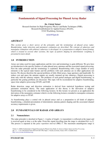
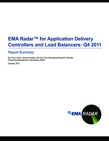
76GHz Millimeter Wave Automobile Radar using Single Chip MMIC1IntroductionSafe driving support technology is an important fieldof development for ITS, and automobile radar a key component of this elemental technology.The development of automobile radar began around1970, followed by the marketing of the Adaptive CruiseControl (ACC) System, a basic driving support system, byauto manufacturers in the late 1990s.Both laser radars and Millimeter wave radars havebeen released. However, the development and expansionof Millimeter wave radars have progressed globally,because of their resistance to fluctuation due to dirty carsand weather conditions (rain, snow and fog).This report introduces the trends in the developmentand application of 76GHz Millimeter wave radar for automobiles, as well as an example of the latest developmentsin this field.nient system to be used at slow-speeds only for trackingcongestion.Although the collision mitigation system currentlyfunctions to simply caution the driver and assist in braking to reduce collision damage, we expect it to evolve intoa hazard evasion system avoid in the future, to avoid bydetecting peripheral hazards and assisting in steering.For the further proliferation of Millimeter wave radarin the future, improvements in function and performanceare required, such as the monitoring of the entire periphery of the vehicle, to achieve a system that is applicable inall situations and driving conditions, whether driving onexpressways or city streets, at high speeds or in congestion.In addition, it is necessary to reduce the cost of sucha system so that it can be utilized as a safety device in awide variety of models in the same manner as airbags andAnti-lock Braking Systems (ABS).Table 1 Trends in the Application of Millimeter Wave Radar2 Trends in the application2.of Millimeter wave radar(Current as of October 2003.)Market Date ManufacturerSystem1998/11 Daimler・ACCChrysler1999/07 Nissan・ACC(CIMA)1999/09 Jaguar・ACC2001/10 BMW・ACC2002/10 Honda(Accord)2003/02 Toyota(Harrier)・ACC・ACC・Collisionmitigation system2003/06 Honda・ACC(Inspire)・Collisionmitigation system2003/08 Toyota・ACC(Celsior)・Collisionmitigation system・ACC2003/10 Honda(Odyssey) ・Collisionmitigation systemVehicle System, PerformanceRecent trends in the application of Millimeter waveradar by various auto manufacturers are shown in Table1. The first Millimeter wave radars measured distancefrom and range rate compared to the preceding vehicle.They were used with a convenient system called theAdaptive Cruise Control (ACC) system, which automatically accelerated and decelerated the vehicle to maintain anappropriate distance from the preceding vehicle while driving. However, there have been indications of changes inthis use since last year.【In addition to such systems, of which the ACC system is merely a single example, the use of collision mitigation systems sold by Honda and Toyota has also begun.These safety support systems detect and warn the operator of potential hazards, and automatically apply thebrakes to reduce damage in the event of a collision.】The development of this collision mitigation systemprogressed within the Advanced Safety Vehicle (ASV)project promoted since 1990 by the Ministry of Land,Infrastructure, and Transport of Japan. Recent improvements in the stability and performance of the sensing ofMillimeter wave radars, which are the "eyes" of the vehicle, have allowed these developments to progress to theactual installation of these systems in automobiles.The collision mitigation system utilizes Millimeterwave radar to detect the preceding vehicle and warn ofthe potential of rear-end collisions. If the distance from thepreceding vehicle becomes too close, the system uses awarning alarm and display to instruct the driver toreduce vehicle speed. However, if the system determinesthat deceleration is insufficient to prevent a collision, it isdesigned to reduce damage by automatically and stronglyapplying the brakes to reduce the collision speed, whilesimultaneously tightening the seat belts to restrain passengers.The predicted evolution of radar application is shownin Figure 1. In the future, we expect an enlargement inthe applicable speed range, for the application of a conve-FeaturesLow GBraking ControlLow GBraking ControlLow GBraking ControlLow GBraking ControlLow GBraking ControlHigh GBraking AssistanceHigh GStrong BrakingHigh GStrong BrakingHigh GStrong BrakingLevel 4Level 2 & 3Level 1・Adaptive Cruise ControlThrottle control Lo-G Brake control・Forward VehicleCollision Warning19982000・Advanced AdaptiveCruise ControlThrottle control Hi-G Brake control・Stop & Go・Pre-crash & collisionmitigation・Following in congestion2005・Total Driving Support SystemThrottle control Brake control Steering control2010Fig.1 Prediction of the Evolution of Radar ApplicationFUJITSU TEN TECH. J. No.23(2004)13
FUJITSU TEN TECHNICHAL JOURNAL3. Requirementsautomobile e radars require the stable detecting of distances to a variety of vehicles, from small motorcycles tolarge trucks, at distances from a few meters to well over100 meters, as well as speeds from 0km/h to 200km/h,regardless of weather conditions or time of day.It is necessary to set the radar beams to scan a certain range of angles, so that, regardless of whether theroad is straight or curves, the relative side positions(angles) can be tracked to determine whether the preceding car is in your lane (where operation of the system maybe necessary) or an adjacent lane.In addition, since radar is installed in the limited spaceat the front of the automobile, it must be contained withindimensions that will not affect the design or cooling performance of the vehicle or hinder safety with respect tocollisions.It is important to make radars available at low cost topromote their proliferation in the market.44. trendsin inautomobileA comparison of recent automobile radars from bothJapanese and other manufacturers is shown in Table2.There are a variety of modulation methods forMillimeter wave radar, such as FM-CW, 2-frequency CW,pulse, and Spread Spectrum (SS). However, FM-CW(Frequency-Modulated Continuous Waves) is utilized mostoften, since the high-frequency band has a comparativelysimple structure, it can measure both distance and rangerate simultaneously with a high degree of precision and itcan also measure range rates of zero.There are two types of methods used for detectingangles in the right and left directions: one is electronicmethods, such as beam conversion and monopulses, andthe other is mechanical antenna scanning methods. Therehave been reports of 3-beam and 9-beam conversions forthe beam conversion method. By increasing the number ofbeams, angle resolution is increased and a wider angle isachieved. There have also been reports of monopulsemethods that detect angle with the reception of two signals, as well as a phased array method in which the beamshape can be modified.Mechanical scanning with antennas allows comparatively simple in wide angles with sharp beams andincreased angle resolution.There have been reports of radars with horizontaldetecting angles from 4 to 10 , showing a trendtoward wider angles.Millimeter wave devices, which are used as 76GHztransceivers have shifted from the use of Gunn diodes tothe use of Monolithic Microwave IC (MMIC), which areeasier to mass-produce. Developments are underway totake advantage of the characteristics of MMIC.5Outline of FUJITSU TEN5. LIMITED Millimeterwave radarsMillimeter wave generally refers to the frequencyrange from 30GHz to 300GHz, which consists of extremelyshort wavelengths (from 10mm to 1mm).FUJITSU TEN LIMITED uses 76GHz for itsMillimeter wave radars, because this is the frequencyselected by the governments in the principal markets ofJapan, the United States, and Europe.Our current Millimeter wave radar systems use theFM-CW radar method, which has a simple structure andallows the measurement of the distance to and range ratecompared to the target vehicle.Table 2 Comparison of Millimeter Wave Radars from Various ManufacturersManufacturer Our companyADCDelphiBoschHonda elesysDensoHitachi89 107 86136 133 68137 67 10091 124 79123 98 7977 107 5380 108 64FM-CWFM PulseFM-CW FM-CWFM-CW2- frequency CWAppearanceExternalDimensions (mm)Modulation MethodDetectionRangeHorizontalDetection AngleAngle DetectionMethodEHF Device4m to 120mApprox.Approx.2m to 120m4m to 100mApprox.Approx.or greater1m to 150m1m to 150mor greateror greater2m to 150m1m to 150mApprox.Approx. 5 5 4 8 10 8 8 CMMICMonopulseMMICFUJITSU TEN TECH. J. No.23(2004)14
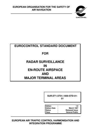
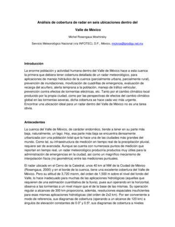
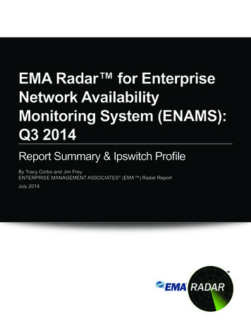
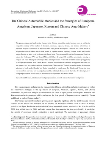
76GHz Millimeter Wave Automobile Radar using Single Chip MMICAntennaMillimeter wave ternalInterfaceVehicleMotorMotor DriveCircuitryScannerFig.2 Radar System Block DiagramThe system configuration for Millimeter wave radar isshown in Figure 2. Millimeter wave radar consists of anantenna, Millimeter wave transceiver, scanner, analog circuitry, digital signal processor, and an external interface.The antenna is connected to the Millimeter wave transceiver, and the locations of obstacles are calculated in thesignal processor. The results of these calculations arerelayed through the transmission interface and output tothe vehicle's control computer.The radar system is shown in Figure 3, and the primary specifications are listed in Table 3.With this Millimeter wave radar system, a planerantenna is connected to an Millimeter wave unit using awaveguide, and an actuator is used to perform left to rightscanning. The radar beat signals are converted to AD inthe signal processor, the frequency is analyzed in the DSPcircuitry, and distance, range rate, and angle informationare calculated to detect the positions of obstacles.The sensor must be able to instantly detect the position and speed of a variety of vehicles, from small motorcycles to large trucks, regardless of time of day or weather conditions. Therefore, the antenna and Millimeter waveunit must have a dynamic range that can detect large andsmall obstacles, as well as being compact enough forinstallation on vehicles and to reduce scanning load.Fig.3 76GHz Millimeter Wave RadarTable 3 Primary Specifications of Millimeter Wave RadarItemSpecificationsRadar MethodFM-CWCentral Frequency76 - 77GHzTransmission Power10mW or lessAntenna PolarizedWave Characteristics45 linear polarized waveMaximum Detection Range Approx.120mFUJITSU TEN TECH. J. No.23(2004)15
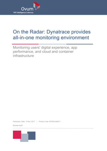
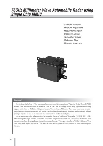
FUJITSU TEN TECHNICHAL JOURNAL6. Planer AntennaThe Millimeter wave transceiver is the most important component in a 76GHz Millimeter wave radar, as wellas the component whose technology has made the mostrapid progress. In order for automobile radar to proliferatein the future, the cost needs to be reduced. Developmentis progressing in making Millimeter wave transceivers,called the heart of Millimeter wave radar, more compactand economical.Specifically, there have been reports of MMIC chipsmounted directly onto multilayer ceramic circuit boards,to develop multilayer boards with built-in via hole construction for 3-dimensional multilayer wiring structureswith 3-dimensional wiring layouts, as well as Millimeterwave signal connections between MMIC and antennas.As one approach toward creating compact, low-costradar, we have developed a method for mounting MMICmodules inside Millimeter wave transceivers, as well as asingle-chip integrated MMIC module applicable to theintegrated IC.The configuration of the Millimeter wave transceiveris shown in Figure 4.We developed a 2-module construction for MMIC.Excluding VCO, all transceiver functions are contained on1 MMIC chip. The single-chip integrated MMIC module issealed in an airtight package to maintain reliability. It consists of an integrated MMIC for transmission and reception which includes frequency multiplier (MLT), mixer(MIX), and amplifier (AMP) functions.Although the configuration of this transceiver systemis the same as our conventional products, the use of a single-chip integrated MMIC module achieves both a unitvolume and weight that are 75% that of our conventionalproducts. In addition, the formation of a high-frequencytransmission line inside the chip allows a reduction in thenumber of connections, allowing simplified production andmore stable performance.Waveguidetransition6.1 Single-chip MMIC (integrated MMIC)A photograph of an integrated MMIC chip is shown inFigure 5. The process used a P-HEMT (PseudomorphicHEMT) with an InGaP/InGaAs heterojunction as the base.The P-HEMT performance is as follows: gate length of0.15μm, transition frequency of 90GHz, and maximum frequency of oscillation of 170GHz. The capacitor has aMetal-Insulator-Metal (MIM) structure using SiN. Theresistance uses an epitaxial activated layer. The area ofthe integrated MMIC chip is 8.46mm2, 1/3 of that for ourconventional MMIC chips. In addition, as shown in thephotograph of the chip in Figure 5, a gold pillar with over250 earths is arranged on the MMIC chip to prevent interference due to unnecessary radiation between circuits.Fig.5 Single Chip Integrated MMICThe performance of the newly developed single-chipMMIC module is shown in Table 4. The transmission performance and reception performance are shown in Figure6 and Figure 7. This new module achieves the same performance as combinations of for our conventional MMICmodules.IF OModuleMMICDriveCircuitryAnalog Circuitry6Fig.4 Millimeter Wave Transceiver Block DiagramFUJITSU TEN TECH. J. No.23(2004)16
76GHz Millimeter Wave Automobile Radar using Single Chip MMICTable 4 Performance of Single Chip Integrated MMIC10ItemOutput Power ain64High-frequencyTransmission Power7.3dBmCharacteristics230.8dB(0dBm@38GHz in)Noise Figure(0dBm@38GHz in)Frequency 77GHz11dB(@IF 1MHz)0-12 -10-8-6-4-200.54WDCConsumed Power20.3WDCLO Power (dBm)Fig.6 Output Power of Single Chip Integrated MMIC6.2 Circuit operation in single-chip integratedMMICA block diagram of a single-chip integrated MMICmodule is shown in Figure 8. As explained in the previoussection, four conventional MMIC chips have been integrated into a single MMIC chip.The integrated MMIC module has a port for the inputof external 38GHz VCO signals, a port for the input andoutput of 76GHz signals, and two IF signal output ports.The signal routes can be broadly classified into the following types: local signal route, transmission signal route, andreception signal route.In transmission mode, the receiving route is turned off,and in reception mode the transmission route is turned off.When switching between transmission and receptionthe drain bias voltage in the transmission amp and thereception amp is adjusted consecutively.Conversion Gain (dB)3530252015LO Power 0dBmIF Frequency 10MHz10747576777879Frequency (GHz)80Fig.7 Conversion Gain for Single Chip Integrated MMICTransmission Area (In receptionmode, this area is off)38GHz InputPortTransmission SignalRoute38GHzAMP4 stageAntenna OAMPLocal Signal Route0-180 HybridCircuitryMIX 2FrequencyMultiplier1 stageAMPHybridCircuitry38GHz6 stageAMPAMPMIXReception Signal RouteIF SignalOutput Port76GHzInput/Output PortMMICDriveCircuitrySingle-Chip Integrated MMIC ModuleReception Area (In transmissionmode, this area is off)Fig.8 Block Diagram for Single Chip Integrated MMICFUJITSU TEN TECH. J. No.23(2004)17
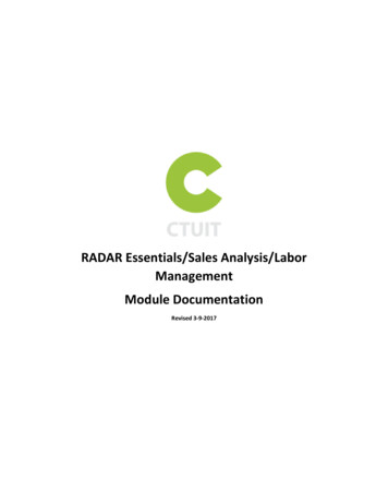
FUJITSU TEN TECHNICHAL JOURNAL7square appearing on the target vehicle in Figure 10 indicates the position detected by the radar, indicating thatthe target has been acquired successfully. In addition, theright side of Figure 10 shows the radar detecting conditions from above. In this area of the figure, distance to thetarget is expressed on the vertical axis and the lateralposition of the target is expressed on the horizontal axis.The target vehicle, enclosed in the dashed-line circle, isdetected at the correct distance and lateral position.150170m or greater4030Distance10020502m010Range Rate (m/s)200Distance (m)The VCO module, which receives a triangular modulating signal, outputs an FM modulated signal. The signalfrom the VCO is divided into two by the 38GHz branchline hybrid circuit. Of the two divided signals, one is alocal signal amplified by the 38GHz amplifier. Then, itenters the frequency multiplier, is re-amplified by the 1ststage amplifier, and sent to the local port of the 76GHzmixer.The other divided signal is amplified by the 38GHzamplifier. Then, it enters the frequency multiplier, isamplified by the amplifier, passes through the 76GHzbranch-line hybrid circuit, and then output from the76GHz input/output port as a transmission signal.The reception signal passes from the 76GHz input/output port through the 76GHz branch-line hybrid circuit,and is then amplified by the amplifier. It is then downconverted from 0-180 degree hybrid circuitry by a single endmixer, and output from the IF signal output port.In this formation of single chip MMIC, the level diagram of transceiver was designed so that it might haveequivalent characteristics to the conventional transceiver.In addition, hybrid circuitry is also built on the chip toreduce cost and size.0-50-10Range RateFig.9 Actual Tracking Performance7. Radarevaluation resultsRadarevaluationresultsThe tracking performance with this newly developedsingle chip MMIC is shown in Figure 9. The figure showsthe detecting performance of distance and range ratewhile gradually approaching a stopped vehicle in the distance. The figure shows that the vehicle can be tracked ina range from more than 170m to 2m. The conditions forthe tracking of the vehicle are shown in Figure 10. TheFigures 11 and 12 show the accuracy for range andrange rate measured using reflectors in fixed positionswith a Radar Cross Section (RCS) value of approximately10m2 (the size of a car). Good test results were achieved.The detection range error for various distances between20m to 160m is less than 1m, and range rate error is lessthan 0.5m/s.Target VehicleDetected TargetRadarFig.10 Test ConditionFUJITSU TEN TECH. J. No.23(2004)18
76GHz Millimeter Wave Automobile Radar using Single Chip MMICconvenient systems, similar to current ACC systems, aswell as for safety, similar to current collision mitigationsystems. However, reductions in cost, as well as improvements in function and performance, will be necessary.We hope to contribute to the enlargement of theMillimeter wave radar market, by promoting technologicaldevelopments in MMIC, the key component of Millime
preceding vehicle becomes too close, the system uses a . are required, such as the monitoring of the entire periph-ery of the vehicle, to achieve a system that is applicable in all situations and driving conditions, whether driving on . Our company