Transcription
Radar Programming ModelKaushal Kukkar, Texas InstrumentsTue 5/9/20171
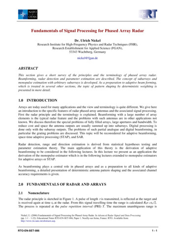
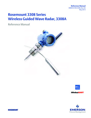
mmWaveLink FrameworkApplicationmmWave APImmWaveGUImmWave rolMonitoringmmWaveLibmmWave Communication ProtocolPlatform Abstraction(SPI/Mailbox, OS)mmWave Front EndRTOS Drivers OSALTI RTOSBootloader (ROM)TI's mmWaveLink framework Is a link between Application and mmWave Radar device Runs on Cortex R4F or DSP and provides low level APIs to control the mmWave Front end Is platform independent and OS agnostic Can be ported to any External MCU and communicates with mmWave device over SPICustom RTOS
mmWaveLink Framework APIsAPIsDescriptionDevice Manager APIsrlDevicePowerOnInitializes the driver and handshake with mmWave Front EndrlDevicePowerOffDe-initializes the driverSensor Control APIsrlSetChannelConfigConfigures the number of RX and TX channelsrlSetAdcOutConfigConfigures the ADC format (# bits, Real/Complex)rlSetProfileConfigConfigures the profile (Frequency start, Frequency slope, Idle time, RX gain, ADC sampling rate, HPF1and HPF2 cutoff, TX output power, TX phase shifter)rlSetChirpConfigConfigures variable part for frequency start, slope, ADC start time, idle time and selection of TX foreach chirprlSetFrameConfigConfigures the frame (start chirp index, end chirp index, number of chirp loops, frame periodicity)rlSensorStartTriggers the transmission of the frames as per the frame and chirp configurationrlSensorStopStops the transmission of the frames.
RF/Sensor ControlRF/Sensor Control Chirp sequencer (Radar Timing Engine) Rx/Tx Channel Rx Analog Chain ADC and Digital Front End Configuration
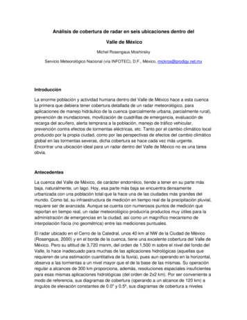
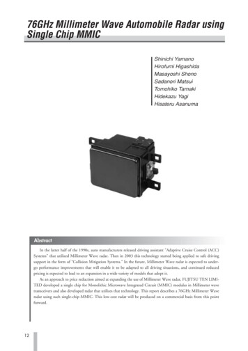
FMCW ChirpRamp EndRamp StartTurn Off TXStart ADC SamplingEnd ADC SamplingADC Sampling Time ADC Samples /Sampling RateADC Valid Start TimeFreq SlopeIdle TimeFreq StartRamp TimeTX Start TimeTurn On TX
FMCW Chirp Range resolution:– Directly proportional to the bandwidth (B) spanned by the chirp.– Bandwidth of 4GHz 4cm Resolutiondres IF Bandwidth: The required IF bandwidth increases with chirp slope (S).– Required IF bandwidth depends on chirp slope and maximum range(dmax )– For given IF bandwidth, maximum range(dmax ) is inversely proportional to Slope (S)Ramp EndRamp Start58uSFreq Start 77 GhzS2dmax cA2A1Ramp StartfIF maxc 2B68 MHz/uSRamp End58uSFreq Start 77 Ghz34 MHz/uS 6
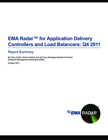
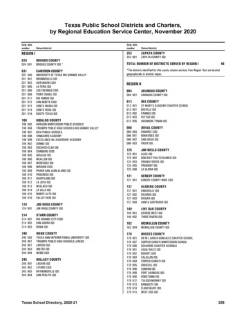
FMCW FrameA1A1A1A1A2A1A2A1A2A3A4A511 A512Frame Sequence of chirps and periodicity of the sequenceFrame StartFrame EndFrame Time (Tf)A1A2A3F1A4A511 A512A1A2A3F2A4FnumFramesA511 A512A1A2A3A4A511 A512Inter-frame timeFrame Periodicity Velocity resolution:– Velocity resolution can be improved by increasing frame time (Tf)– A Tf of 5ms vres of 1.5 kmphvres 𝜆2Tf
Profile RAM and Chirp RAM*Both RAMs are ECC protected
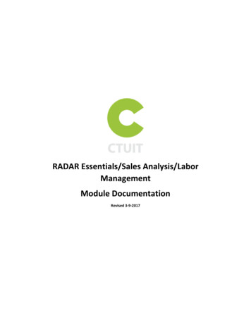
Example UsecaseChirp Cycle TimeTurn Off TXRamp StartStart ADC SamplingEnd ADC SamplingRamp EndADC Sampling Time ADC Samples (225)/ Sampling Rate (4.5 msps)ADC Start Time 3uSFreq Slope 68Mhz/usIdle Time 7uSRamp Time 58uSFreq Start 77 GhzTX Start TimeTransmitter is ONTurn On TXFrame StartFrame End chirpStartIdx Frame periodicity 20msecchirpEndIdx 1chirpStartIdx A1chirpEndIdx 0A2A1 A2A1Inter-frame timeA2A1 A2A1A2A1A2
Profile ConfigurationTypeNamerlUInt16 trlUInt32 tprofileIdstartFreqConstProfile index for which rest of the properties are applicableFrequency profile for each profile.1 LSB 3.6e9/2 26 54 HzidleTimeConstIdle time for each profile1 LSB 10 nsadcStartTimeConstADC capture time for each profile.1 LSB 10 nsrampEndTimeRamp end of each profile.1 LSB 10nstxOutPowerBackoffCode TX channel output power backoff.b7:0- TX0 output power backoffb15:8-TX1 output power backoffb23:16-TX2 output power backoff1 LSB 1 dBHzValue to beprogrammed00x558E38E3ns700ns300ns5800dB0rlUInt32 ttxPhaseShifterdegree0rlInt16 tfreqSlopeConstkHz/μs0x580rlUInt32 trlUInt32 trlUInt32 trlUInt32 tDescriptionTX channel phase shift valueb7:0 - TX0 phase shift valueb15:8 - TX1 phase shift valueb23:16 - TX2 phase shift value1 LSB 5 Frequency slope for each profile1LSB 3.6e9*900/2 26 48 kHz/μsUnits
Profile ConfigurationTypeNameDescriptionUnitsrlInt16 ttxStartTimensrlUInt16 trlUInt16 tnumAdcSamplesdigOutSampleRateksps2254500rlUInt8 thpfCornerFreq1Hz0x00rlUInt8 thpfCornerFreq2Hz0x00rlUInt8 trxGainTX start time1 LSB 10nsNumber of ADC samples to capture in a chirp for each RXADC sampling rate1 LSB 1 kspsHPF1 corner frequency for each profile0x00– 175kHz0x01- 235kHz0x02- 350kHz0x03- 700kHzHPF2 corner frequency for each profile0x00– 350kHz0x01- 700kHz0x02- 1.4MHz0x03- 2.8MHzRX gain for each profile1LSB 1dBValue to beprogrammed0dB0x1EConfigure profilerlProfileCfg t profileCfgArgs;/* Fill profile configuration structure */rlSetProfileConfig(RL DEVICE MAP CASCADED 1, &profileCfgArgs);
Chirp Configuration (1/2)TypeNameDescriptionUnitsrlUInt16 trlUInt16 tchirpStartIdxchirpEndIdx-rlUInt16 trlUInt32 tprofileIdstartFreqVarHz00rlInt16 tfreqSlopeVarkHz/μs0rlUInt16 tidleTimeVarns0 (0ns)rlUInt16 tadcStartTimeVarns0 (0ns)rlUInt16 ttxEnableChirp start index valid range 0 to 511Chirp start index valid range chirpStartIdxto 511Profile index valid range 0 to 3Ramp start frequency variation1 LSB 3.6e9/2 26 54 HzRamp slope variation1 LSB 3.6e9*900/2 26 48 kHz/μsIdle time for each chirp1 LSB 10 nsADC start time for each chirp1 LSB 10 nsTX enable bitmaskb0 : TX0 Enableb1 : TX1 Enableb2 : TX2 EnableValue to beprogrammed00-1 (TX0)
Chirp Configuration (2/2)TypeNameDescriptionUnitsrlUInt16 trlUInt16 trlUInt16 trlUInt32 t16 tfreqSlopeVarkHz/μs0rlUInt16 tidleTimeVarns0 (0ns)rlUInt16 tadcStartTimeVarns0 (0ns)rlUInt16 tatxEnableChirp start index valid range 0 to 511Chirp start index valid range chirpStartIdx to 511Profile index valid range 0 to 3Ramp start frequency variation1 LSB 3.6e9/2 26 54 HzRamp slope variation1 LSB 3.6e9*900/2 26 48 kHz/μsIdle time for each chirp1 LSB 10 nsADC start time for each chirp1 LSB 10 nsTX enable bitmaskb0 : TX0 Enableb1 : TX1 Enableb2 : TX2 EnableValue to beprogrammed1100-4 (TX2)Configure chirprlChirpCfg t chirpCfgArgs[2U];/* Fill chirp #0(chirpCfgArgs[0]) and chirp #1(chirpCfgArgs[1]) configuration structure*/rlSetChirpConfig(RL DEVICE MAP CASCADED 1, 2U, chirpCfgArgs);
Frame ConfigurationTypeNameDescriptionUnitsrlUInt16 trlUInt16 trlUInt16 tchirpStartIdxchirpEndIdxnumLoops-rlUInt16 tnumFrames-0 (Infinite)rlUInt32 tframePeriodicityns4000000rlUInt16 ttriggerSelectrlUInt32 tframeTriggerDelayChirp start index. Valid range 0-511Chirp end index. Valid range from chirpStartIdx to 511Number of times to repeat from chirpStartIdx to chirpEndIdxin each frameNumber of frames to transmitSet 0 for infinite framesFrame repetition period1LSB 5nsFrame trigger method0x0001: SW API based triggering.0x0002: HW SYNC IN based triggering.Optional time delay from the SYNC IN trigger to theoccurrence of frame chirps.1LSB 1nsValue to beprogrammed0132Configure framerlFrameCfg t frameCfgArgs;/* Fill frame configuration structure */rlSetFrameConfig(RL DEVICE MAP CASCADED 1, & frameCfgArgs);1ns0
Rx/Tx Channel configurationTypeNameDescriptionUnitsrlUInt16 trxChannelEn-rlUInt16 ttxChannelEn-0x5 (TX1, TX3)rlUInt16 tcascadingRX Channel Enable/disableb0 – RX Channel 0, b1 – RX Channel 1b2 – RX Channel 2, b3 – RX Channel 3b15:4 – ReservedTX Channel Enable/disableb0 – TX Channel 0, b1 – TX Channel 1b2 – TX Channel 2, b15:3 – ReservedCascading enable0x0000 SINGLECHIP: Single mmWave sensor application0x0001 MULTICHIP MASTER: This mmwave device is the masterchip and generates LO and conveys to other mmwave sensors0x0002 MULTICHIP SLAVE: This mmwave device is a slave chipand uses LO conveyed to it by the master mmwave sensor.Value to beprogrammed0xF-0Configure Tx/Rx ChannelsrlChanCfg t rfChanCfgArgs {0};/* Fill profile configuration structure */rlSetChannelConfig(RL DEVICE MAP CASCADED 1, & rfChanCfgArgs);
ADC configurationTypeNameDescriptionUnitsrlUInt32 tadcBits-rlUInt32 tadcOutFmtNumber of ADC bits00: 12 bits01: 14 bits10: 16 bitsADC output Format00:Real01:Complex 1x (image band filtered output)10:Complex 2x (Image band visible)Value to /2Complex 1XConfigure ADC outputrlAdcOutCfg t adcOutCfgArgs {0};/* Fill ADC output configuration structure Inband0Complex 2Xfs/2-fs/2Inband0Realfs/2
Sensor Control Trigger the framerlSensorStart(RL DEVICE MAP CASCADED 1) Stop the framerlSensorStop(RL DEVICE MAP CASCADED 1)
Data CaptureADCBuffer 1 ADCBuffer 2Digital FrontEndCLKChirpProfile ChirpBuffer 1ProfileBuffer 2ChirpQuality ChirpBuffer 1QualityBuffer 2Data Capture High Speed interface(LVDS/CSI2) selection Data format and rate configuration Lane configuration Interface specific configurationsCBUFFLVDS/CSI2D0D1D2D3
mmWave Data Control (1/4)TypeNameDescriptionUnitsrlUInt8 tintfSel-rlUInt8 ttransferFmtPkt0-1rlUInt8 ttransferFmtPkt1Data path interface select0 – CSI21 – LVDSData Output format000001b ADC000110b CP ADC001001b ADC CP110110b CP ADC CQOthersReserved000000b Suppress Packet 1transmission.001110b CP CQ001011b CQ CPOthersReservedValue to beprogrammed1-0Configure data path interfacerlDevDataPathCfg t devDataPathArgs {0};/* Fill data path configuration structure */rlDeviceSetDataPathConfig(RL DEVICE MAP CASCADED 1, &devDataPathArgs);
mmWave Data Control (2/4)TypeNameDescriptionUnitsrlUInt8 tlaneClkCfg-rlUInt8 tdataRateBitmap for the lane clock selection0 : SDR Clock1 : DDR ClockBitmap for data rate selection0000b900 Mbps (DDR only)0001b600 Mbps (DDR only)0010b450 Mbps (SDR, DDR)0011b400 Mbps (DDR only)0100b300 Mbps (SDR, DDR)0101b225 Mbps (DDR only)0110b150 Mbps (SDR, DDR)Value to beprogrammed1-2 (450 Mbps DDR)Configure HSI clockrlDevDataPathClkCfg dataPathClkCfgArgs {0};/* Fill data path clock configuration structure */retVal rlDeviceSetDataPathClkConfig(RL DEVICE MAP CASCADED 1, &dataPathClkCfgArgs);Ensure data rate meets this criterionNumBitsPerChirp * NumRxChannels/NumLanes RampDuration * dataRateFor e.g. (256 * 4 * 8) * 4/2 60µs * 450Mbps
mmWave Data Control (3/4)TypeNameDescriptionUnitsValue to beprogrammedrlUInt8 trlrlUInt32 trxChannelEnb2AdcBits:2-0xF01 (14 Bits)rlUInt32 tb2AdcOutFmt:2-01 (Complex1x)rlUInt8 tiqSwapSel-0rlUInt8 tchInterleaveBitmap for each of the RX channelNumber of ADC bits00: 12 bits01: 14 bits10: 16 bitsADC output Format00: Real01: Complex 1x(image band filtered output)10: Complex 2x(Image band visible)IQ bit swap selection00 – Sample Interleave Mode - I first01 – Sample Interleave Mode – Q first00 – Interleaved mode of storage01 – Non-Interleaved mode-0Configure data formatrlDevDataFmtCfg dataFmtCfgArgs {0};/* Fill data format configuration structure */retVal rlDeviceSetDataFmtConfig(RL DEVICE MAP CASCADED 1, &dataFmtCfgArgs);
mmWave Data Control (4/4)TypeNameDescriptionrlUInt16 tlaneEnrlUInt16 tReservedLane enable bitmap.b0 - LANE0 EN0Disable lane 01Enable lane 0b1 - LANE1 EN0Disable lane 11Enable lane 1b2 - LANE2 EN0Disable lane 21Enable lane 2b3 - LANE3 EN0Disable lane 31Enable lane 3b15:4ReservedReservedConfigure the lanesrlDevLaneEnable t laneEnCfgArgs {0};/* Fill Lane enable parameters */retVal rlDeviceSetLaneConfig(RL DEVICE MAP CASCADED 1, &laneEnCfgArgs);UnitsValue to beprogrammed0xF
Frame StartFrame EndFrame periodicity 20msecchirpStartIdx chirpEndIdx 0A1A2A1A2A1SummarychirpStartIdx chirpEndIdx 1A2A1A2A1A2A1A2Inter-frame time rlDevicePowerOn Initializes the device driver and opens SPI/Mailboxfor communication rlDeviceRfStart Turns on mmWave Front End rlSetChannelConfig Configures the RF channels which will be in userlSetAdcOutConfig Sets the ADC output format, real/complex moderlSetLowPowerModeConfig Configures the low power optionsrlRfInit Initializes the RF subsystem with one time calibrationsrlSetProfileConfig Configure one profile (say A)rlSetChirpConfig Configure all chirps and associate them to a profile.Also configure variable parameters per chirp rlSetFrameConfig Configure the frame rlDeviceSetDataPathConfig Sets the Data Path I/F rlDeviceSetDataPathClkConfig Selects the datarate rlDeviceSetDataFmtConfig Selects the data format rlDeviceSetLaneConfig Selects the CSI2/LVDSlanes rlSensorStart Starts the frame
09.05.2017 · Profile Configuration Type Name Description Units Value to be programmed rlUInt16_t profileId Profile index for which rest of the properties are applicable - 0 rlUInt32_t startFreqConst Frequency profile for each profile. 1 LSB 3.6e9/2 26 54 Hz Hz 0x558E38E3 rlUInt32_t idleTimeConst Idle time for each profile 1 LSB 10 ns