Transcription
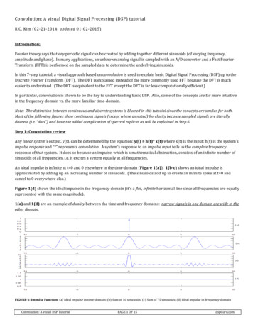
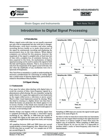
Fundamentals of Signal Processing for Phased Array RadarDr. Ulrich NickelResearch Institute for High-Frequency Physics and Radar Techniques (FHR),Research Establishment for Applied Science (FGAN),53343 Wachtberg, Germanynickel@fgan.deABSTRACTThis section gives a short survey of the principles and the terminology of phased array radar.Beamforming, radar detection and parameter estimation are described. The concept of subarrays andmonopulse estimation with arbitrary subarrays is developed. As a preparation to adaptive beam forming,which is treated in several other sections, the topic of pattern shaping by deterministic weighting ispresented in more detail.1.0 INTRODUCTIONArrays are today used for many applications and the view and terminology is quite different. We give herean introduction to the specific features of radar phased array antennas and the associated signal processing.First the radar principle and the terminology is explained. Beamforming with a large number of arrayelements is the typical radar feature and the problems with such antennas are in other applications notknown. We discuss therefore the special problems of fully filled arrays, large apertures and bandwidth. Toreduce cost and space the antenna outputs are usually summed up into subarrays. Digital processing isdone only with the subarray outputs. The problems of such partial analogue and digital beamforming, inparticular the grating problems are discussed. This topic will be reconsidered for adaptive beamforming,space-time adaptive processing (STAP), and SAR.Radar detection, range and direction estimation is derived from statistical hypotheses testing andparameter estimation theory. The main application of this theory is the derivation of adaptivebeamforming to be considered in the following lectures. In this lecture we present as an application thederivation of the monopulse estimator which is in the following lectures extended to monopulse estimatorsfor adaptive arrays or STAP.As beamforming plays a central role in phased arrays and as a preparation to all kinds of adaptivebeamforming, a detailed presentation of deterministic antenna pattern shaping and the associated channelaccuracy requirements is given.2.0 FUNDAMENTALS OF RADAR AND ARRAYS2.1NomenclatureThe radar principle is sketched in Figure 1. A pulse of length τ is transmitted, is reflected at the target andis received again at time t0 at the radar. From this signal travelling time the range is calculated R0 ct0 /2.The process is repeated at the pulse repetition interval (PRI) T. The maximum unambiguous range isNickel, U. (2006) Fundamentals of Signal Processing for Phased Array Radar. In Advanced Radar Signal and Data Processing(pp. 1-1 – 1-22). Educational Notes RTO-EN-SET-086, Paper 1. Neuilly-sur-Seine, France: RTO. Available SET-0861-1
Form ApprovedOMB No. 0704-0188Report Documentation PagePublic reporting burden for the collection of information is estimated to average 1 hour per response, including the time for reviewing instructions, searching existing data sources, gathering andmaintaining the data needed, and completing and reviewing the collection of information. Send comments regarding this burden estimate or any other aspect of this collection of information,including suggestions for reducing this burden, to Washington Headquarters Services, Directorate for Information Operations and Reports, 1215 Jefferson Davis Highway, Suite 1204, ArlingtonVA 22202-4302. Respondents should be aware that notwithstanding any other provision of law, no person shall be subject to a penalty for failing to comply with a collection of information if itdoes not display a currently valid OMB control number.1. REPORT DATE2. REPORT TYPE01 SEP 2006N/A3. DATES COVERED-4. TITLE AND SUBTITLE5a. CONTRACT NUMBERFundamentals of Signal Processing for Phased Array Radar5b. GRANT NUMBER5c. PROGRAM ELEMENT NUMBER6. AUTHOR(S)5d. PROJECT NUMBER5e. TASK NUMBER5f. WORK UNIT NUMBER7. PERFORMING ORGANIZATION NAME(S) AND ADDRESS(ES)Research Institute for High-Frequency Physics and Radar Techniques(FHR), Research Establishment for Applied Science (FGAN), 53343Wachtberg, Germany9. SPONSORING/MONITORING AGENCY NAME(S) AND ADDRESS(ES)8. PERFORMING ORGANIZATIONREPORT NUMBER10. SPONSOR/MONITOR’S ACRONYM(S)11. SPONSOR/MONITOR’S REPORTNUMBER(S)12. DISTRIBUTION/AVAILABILITY STATEMENTApproved for public release, distribution unlimited13. SUPPLEMENTARY NOTESSee also ADM001925, Advanced Radar Signal and Data Processing., The original document contains colorimages.14. ABSTRACT15. SUBJECT TERMS16. SECURITY CLASSIFICATION OF:a. REPORTb. ABSTRACTc. THIS PAGEunclassifiedunclassifiedunclassified17. LIMITATION OFABSTRACT18. NUMBEROF PAGESUU8119a. NAME OFRESPONSIBLE PERSONStandard Form 298 (Rev. 8-98)Prescribed by ANSI Std Z39-18
Fundamentals of Signal Processing for Phased Array Radartherefore Rmax cT /2. The ratio η τ /T is called the duty factor.TxTxRxτt0 /2t0R02R0T2RmaxDead zoneDead zonetrFigure 1: The principle of radar receptionThe received signal-to-noise power ratio (SNR) isdescribed by the radar equationPSignalPmGt σ 0 Gr λ 211 SNR (4π R 2 )2 Pnoise (4π ) 2 R 4(kT0 FB) LRtarget range(km)Pmmean power of transmit pulse (W)Gt, Gr gain of transmit/ receive antennaσ0radar cross section of target (m²)λwavelength(cm)kT0 4*10-21 Ws(W/Hz)Fnoise figure(dim-less)Bbadwidth(Hz)Llosses(dim-less)It is the 1/R4 law that forces the radar designer to increase transmit or receive energy as much as possible.Fast time processing: The received pulse is filtered such that the signal energy is maximally extracted(matched filtering, pulse compression). This is achieved by convolving the received data samples zk withLthe transmit wave form sk, k 1.L, yk sr zk r . The range resolution after pulse compression is givenr 1by R cτ /2, where τ is the effective pulse length aftersignal modelcompression. By suitable coding long transmit pulseswith short length after compression and thus high rangeresolution can be constructed. This requires a largerrangeΣbandwidth. The ratio of the pulse length before and after(fast time)compression is called the compression ratio K which isthe same as the time-bandwidth product, K τ before/τafter B τ before. Analogue waveforms like linearfrequency modulation (or chirp) are used for pulse compression, or discrete codes which are switched atcertain subpulses, e.g. binary codes or polyphase codes. For radar the sidelobes after pulse compressionare important to avoid false targets. Also, the compressed pulse must be tolerant against Dopplerfrequency shifts which a typical echo of a moving target has.Slow time processing: The receiver signal energy can be increased by integrating the power from pulse topulse. The echo of a target with certain radial velocity vR undergoes a frequency shift fD 2vR/λ due to theDoppler effect. From pulse to pulse at PRI T we observe thus a phase shift φD 2πfDT. Maximum energy iscollected if this shift is compensated. The summation with correct phase compensation is called coherentKintegration,y e j 2π f D kT yk . Of course, the radial velocity and hence the Doppler frequency fD isk 1unknown and must be estimated. The integration time KT is called coherent processing interval, CPI.1-2RTO-EN-SET-086
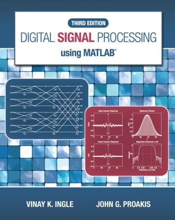
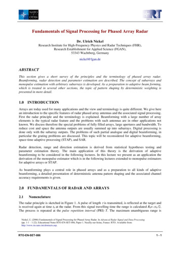
Fundamentals of Signal Processing for Phased Array RadarAlternatively one may sum up only the magnitude, called incoherent integration,y2K yk . The2k 1time of all processing in a fixed look direction of the radar (e.g. with several CPIs) is called the dwell time.2.2The phased array principleThe principle of phased arrays is to generate a plane wavefront from a large number of elementaryspherical waves as sketched in Figure 2. Some technical realisations of array antennas are also shown inthis figure. The spherical waves are approximately realised by elementary antenna elements with nearomni-directional characteristic. The application of suitable excitations at the elementary antennas and thesummation of all signals on receive is called beamforming.Figure 2: Principle of array antenna and some realisations of phased arraysWhy are phased array antennas of interest? The main advantage is the nearly infinitely fast switching ofthe look direction of the array. This allows to illuminate the search space according to some optimalitycriterion instead of according to a continuous mechanical movement. Recall that the 1/R4 law forces us toconcentrate transmit energy. All aspects of optimising target illumination the received energy are denotedby the key word energy management, which is the principle advantage of phased arrays. Particularcomponents of energy management areCoherent integration can be made nearly arbitrarily long. This allows better clutter suppression(Doppler discrimination), target classification by extracting spectral features, and finally SAR andISAR processing.Performance of different radar task in time multiplex, like search and tracking of multiple targets. Thisallows to use one phased array radar as multi-function radar.Optimisation of individual radar tasks: optimised waveforms for search, acquisition and track, highprecision measurements when required, variable beam shapes, optimised algorithms for tracking (theRTO-EN-SET-0861-3
Fundamentals of Signal Processing for Phased Array Radarradar is “steered” by the tracking algorithm and a-priori information)Lower prime energy consumption (only for active array, saving of about a factor of 2)High mean time between failure (MTBF) due to graceful degradation (only active array)If spatial samples over the antenna aperture are available: adaptive beam forming (ABF), space-timeadaptive processing (STAP), super-resolution2.3BeamformingOne of the key technical problems of phased arrays is the beamforming operation. To sum all signalscoherently the time delay of the signal received at antenna element at position r (x,y,z)T has to becompensated. We denote the angle of incidence of an incoming plane wave by the unit direction vector inthe antenna coordinate system u as indicated in Figure 3 (sometimes called the “direction cosines”). Theplane in green may represent the aperture of a planar antenna. The formulas are also valid for 3dimensional arrays. The path length difference between the element at position r and the origin is then justrT u xu yv zw r u cos ( r, u ) . For a linear antenna as indicated in the left hand subplot of 1Figure 3 this is equal to x sin θ .uuθruyvuxFigure 3: Delays and direction cosinesThe signal at element r is written as sr ( t , u ) b e j 2π f t e j 2π f rTu/c, where f is the transmit frequency andc the velocity of light. Correspondingly, we form a beam into a direction u0 with N antenna elements bycompensating these delaysNSt (u, u 0 ) e j 2π f rk u0 / c srk (t , u) a H (u0 ) s(t , u) .k 1T(1)ak (u0 )The superscript H denotes conjugate transpose. We call a(u0) the steering vector. For the special case of alinear antenna with equidistant elements at xk kdλ/2 (the elements are separated by dλ/2) this results inthe well known function1-4RTO-EN-SET-086
Fundamentals of Signal Processing for Phased Array RadarNNSt (u , u0 ) sk (t , u ) e j 2π f xk u0 / c b e j 2π f t ek 1 b e j 2π f t ej2πλ demodulationλxk ( u u0 )xk ( u u0 )k 1N2πk 1Nb ejj2πλxk ( u u0 ) b k 1(2)sin Nπ d ( u u0 )sin π d ( u u0 )f (u u0 )The function f(u) a(0)Ha(u) is called the antenna (directivity) pattern. From (2) one can see that for auniform linear antenna this is obviously a periodic function, as for any integer p we have an up such thatπNd u 2πp πNd up. This means for element distances d 1 we have angles in the visible region up 1where the main beam is repeated, called the grating lobes. Such grating lobes can be avoided if irregulardistances are chosen. Array with irregular spacings are often chosen to achieve a narrow beamwidth withfew antenna elements (e.g. minimum redundancy arrays, thinned arrays).The (directivity) gain in a direction u0 of the antenna is defined asG f (u 0 )21Ω f (u u 0 ) du ,2(3)Ωwhere Ω denotes the visible region, i.e. Ω {(u,v) u² v² 1}. With phase-only beam steering, the gain isapproximately equal to the number of elements, G N. Thus to achieve high gain a large number ofelements is needed.2BW2The 3 dB beamwidth BW is defined as f (u0 ) 1/ 2 f (u0 ) . For uniform linear antennas we2have BW 0.887/A, or θBW 51/A[ ], where A denotes the diameter (length) of the antenna aperturemeasured in units of the wavelength λ. For planar arrays we have approximately BW 1/A, or θBW 60/A[ ].Optimum beamforming depends obviously on the signal frequency. The beamforming operation bymultiplying the signal with a suitable phase shift is therefore only correct for very narrowband signals. Forbroadband signals we have to apply at each antenna element the true time delays (TTD) τ k rkT u 0 / c . Thisis called broadband beamforming indicating that a “phased” array is always narrowband.What does narrowband mean in this context? First, note that for planar phased arrays we have a u f ffrequency-angle ambiguity exp[ j 2π ( f f ) r T u / c] exp[ j 2π f r T (u u ) / c] , such thatfuf u v fand . From this one can derive a rule of thumb for the angle error induced by a frequencyvf fdeviation of f: θ [ ] [%] at θ 60 , which is usually the maximum scan angle. One can now setfan admissible beam pointing error at the maximum scan angle to obtain the admissible bandwidth. For atypical definition of narrowband one sets θ θBW . This mean e.g. that for a pointing error less than 3 wehave an admissible relative bandwidth below 3%.RTO-EN-SET-0861-5
Fundamentals of Signal Processing for Phased Array RadarA broadband source can be written as a sum (integral) of independent sources over all frequencies of theband. For a narrowband phased array such a source looks like an extended sour
Digital processing is done only with the subarray outputs. The problems of such partial analogue and digital beamforming, in particular the grating problems are discussed. This topic will be reconsidered for adaptive beamforming, space-time adaptive processing (STAP), and SAR. Radar detection, range and direction estimation is derived from statistical hypotheses testing and parameter .