Transcription
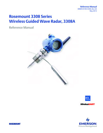
Reference Manual00809-0100-4308, Rev AAMay 2013Rosemount 3308 SeriesWireless Guided Wave Radar, 3308AReference Manual
Reference ManualTitle Page00809-0100-4308, Rev AAMay 2013Rosemount 3308 Series WirelessGuided Wave Radar Level TransmitterRosemount 3308A Hardware RevisionHART Device RevisionField Communicator Field Device Revision11Dev v1, DD v1NOTICERead this manual before working with the product. For personal and system safety, and foroptimum product performance, make sure you thoroughly understand the contents beforeinstalling, using, or maintaining this product.The United States has two toll-free assistance numbers and one international number.Customer Central1-800-999-9307 (7:00 a.m. to 7:00 p.m. CST)North American Response Center1-800-654-7768 (24 hours a day)Equipment service needsInternational1-952-906-8888Explosions could result in death or serious injury.Verify that the operating environment of the gauge is consistent with the appropriatehazardous locations certifications.Installation of device in an explosive environment must be in accordance with appropriatelocal, national and international standards, codes, and practices.Ensure device is installed in accordance with intrinsically safe or non-incendive fieldpractices.iii
Title PageReference ManualMay 201300809-0100-4308, Rev AAElectrical shock can result in death or serious injury.Ground device on non-metallic tanks (e.g. fiberglass tanks) to prevent electrostatic chargebuild-up.Single lead probes are sensitive for strong electromagnetic fields and therefore not suitablefor non-metallic tanks.Care must be taken during transportation of power module to prevent electrostatic chargebuild-up.Device must be installed to ensure a minimum antenna separation distance of 8 in. (20 cm)from all persons.Probes covered with plastic and/or with plastic discs may generate an ignition-capable levelof electrostatic charge under certain extreme conditions. Therefore, when the probe isused in a potentially explosive atmosphere, appropriate measures must be taken to preventelectrostatic discharge.Process leaks could result in death or serious injury.Only qualified personnel should install the equipment.Install transmitter prior to process start-up.Install and tighten process connectors before applying pressure.Handle the transmitter carefully.Do not remove the transmitter while in operation.If the process seal is damaged, gas could escape from the tank when removing thetransmitter head from the probe.Any substitution of non-recognized parts may jeopardize safety. Repair, e.g. substitution ofcomponents etc., may also jeopardize safety and is under no circumstances allowed.iv
Reference ManualTitle Page00809-0100-4308, Rev AAMay 2013This device complies with Part 15 of the FCC Rules. Operation is subject to the followingconditions: This device may not cause harmful interference. This device must accept anyinterference received, including interference that may cause undesired operation. Thisdevice must be installed to ensure a minimum antenna separation distance of 20 cm (8 in.)from all persons.The products described in this document are NOT designed for nuclear-qualifiedapplications.Using non-nuclear qualified products in applications that require nuclear-qualifiedhardware or products may cause inaccurate readings.For information on Rosemount nuclear-qualified products, contact your local EmersonProcess Management Sales Representative.NOTICEPower Module Considerations.Each Power Module contains two "C" size primary lithium/thionyl chloride batteries. Eachbattery contains approximately 2.5 grams of lithium, for a total of 5 grams in each pack.Under normal conditions, the battery materials are self-contained and are not reactive aslong as the batteries and the pack integrity are maintained. Care should be taken to preventthermal, electrical or mechanical damage. Contacts should be protected to preventpremature discharge.Battery hazards remain when cells are discharged.Power modules should be stored in a clean and dry area. For maximum battery life, storagetemperature should not exceed 30 C.The Power Module may be replaced in a hazardous area. The Power Module has surfaceresistivity greater than one gigaohm and must be properly installed in the wireless deviceenclosure. Care must be taken during transportation to and from the point of installation toprevent electrostatic charge build-up.v
Title PageMay 2013viReference Manual00809-0100-4308, Rev AA
Reference ManualTable of Contents00809-0100-4308, Rev AAMay 2013Contents1Section 1: Introduction1.1 Service support. . . . . . . . . . . . . . . . . . . . . . . . . . . . . . . . . . . . . . . . . . . . . . . . . . . . . . . . . 11.2 Product recycling/disposal . . . . . . . . . . . . . . . . . . . . . . . . . . . . . . . . . . . . . . . . . . . . . . . 22Section 2: Transmitter Overview2.1 Theory of operation . . . . . . . . . . . . . . . . . . . . . . . . . . . . . . . . . . . . . . . . . . . . . . . . . . . . . 32.2 Emerson's Smart Wireless. . . . . . . . . . . . . . . . . . . . . . . . . . . . . . . . . . . . . . . . . . . . . . . . 62.3 Application characteristics . . . . . . . . . . . . . . . . . . . . . . . . . . . . . . . . . . . . . . . . . . . . . . . 62.3.1 Tank shape . . . . . . . . . . . . . . . . . . . . . . . . . . . . . . . . . . . . . . . . . . . . . . . . . . . . . . . 62.3.2 In-tank obstructions . . . . . . . . . . . . . . . . . . . . . . . . . . . . . . . . . . . . . . . . . . . . . . . 72.3.3 Interface level measurement . . . . . . . . . . . . . . . . . . . . . . . . . . . . . . . . . . . . . . . 72.4 Application examples . . . . . . . . . . . . . . . . . . . . . . . . . . . . . . . . . . . . . . . . . . . . . . . . . . . 92.5 Components of the transmitter . . . . . . . . . . . . . . . . . . . . . . . . . . . . . . . . . . . . . . . . .102.6 Probe selection guide for the Rosemount 3308 Series transmitter . . . . . . . . . . .113Section 3: Installation3.1 Safety messages . . . . . . . . . . . . . . . . . . . . . . . . . . . . . . . . . . . . . . . . . . . . . . . . . . . . . . .133.2 Installation procedure . . . . . . . . . . . . . . . . . . . . . . . . . . . . . . . . . . . . . . . . . . . . . . . . . .163.3 Review mounting considerations . . . . . . . . . . . . . . . . . . . . . . . . . . . . . . . . . . . . . . . .173.3.1 Recommended mounting position . . . . . . . . . . . . . . . . . . . . . . . . . . . . . . . . .173.3.2 Flange connection on nozzles . . . . . . . . . . . . . . . . . . . . . . . . . . . . . . . . . . . . .193.3.3 Non-metallic tanks . . . . . . . . . . . . . . . . . . . . . . . . . . . . . . . . . . . . . . . . . . . . . . .193.4 Review mounting preparations . . . . . . . . . . . . . . . . . . . . . . . . . . . . . . . . . . . . . . . . . .203.4.1 Measure Tank Height . . . . . . . . . . . . . . . . . . . . . . . . . . . . . . . . . . . . . . . . . . . . .203.4.2 Shorten the probe. . . . . . . . . . . . . . . . . . . . . . . . . . . . . . . . . . . . . . . . . . . . . . . .213.4.3 Mount a Centering disc for pipe installations . . . . . . . . . . . . . . . . . . . . . . . .263.5 Anchor the probe . . . . . . . . . . . . . . . . . . . . . . . . . . . . . . . . . . . . . . . . . . . . . . . . . . . . . .273.5.1 Flexible Single/Twin Lead probe. . . . . . . . . . . . . . . . . . . . . . . . . . . . . . . . . . . .273.5.2 Rigid Single Lead probe . . . . . . . . . . . . . . . . . . . . . . . . . . . . . . . . . . . . . . . . . . .283.5.3 Coaxial probe. . . . . . . . . . . . . . . . . . . . . . . . . . . . . . . . . . . . . . . . . . . . . . . . . . . .293.6 Mount device on tank . . . . . . . . . . . . . . . . . . . . . . . . . . . . . . . . . . . . . . . . . . . . . . . . . .303.6.1 Threaded tank connection . . . . . . . . . . . . . . . . . . . . . . . . . . . . . . . . . . . . . . . .303.6.2 Tank connection with flange . . . . . . . . . . . . . . . . . . . . . . . . . . . . . . . . . . . . . .313.6.3 Tank connection with loose flange (“plate design”) . . . . . . . . . . . . . . . . . .323.7 Install Remote Housing . . . . . . . . . . . . . . . . . . . . . . . . . . . . . . . . . . . . . . . . . . . . . . . . .323.8 Ground the device . . . . . . . . . . . . . . . . . . . . . . . . . . . . . . . . . . . . . . . . . . . . . . . . . . . . .33Table of Contentsi
Reference ManualTable of Contents00809-0100-4308, Rev AAMay 20133.9 Install the power module . . . . . . . . . . . . . . . . . . . . . . . . . . . . . . . . . . . . . . . . . . . . . . .343.10Position the antenna . . . . . . . . . . . . . . . . . . . . . . . . . . . . . . . . . . . . . . . . . . . . . . . . . . .343.11Utilize the device display . . . . . . . . . . . . . . . . . . . . . . . . . . . . . . . . . . . . . . . . . . . . . . .353.11.1Rotate the device display . . . . . . . . . . . . . . . . . . . . . . . . . . . . . . . . . . . . . . . . .353.11.2Retrofitting . . . . . . . . . . . . . . . . . . . . . . . . . . . . . . . . . . . . . . . . . . . . . . . . . . . . .354Section 4: Configuration4.1 Overview . . . . . . . . . . . . . . . . . . . . . . . . . . . . . . . . . . . . . . . . . . . . . . . . . . . . . . . . . . . . .374.2 Safety messages . . . . . . . . . . . . . . . . . . . . . . . . . . . . . . . . . . . . . . . . . . . . . . . . . . . . . . .384.3 Configuration procedure . . . . . . . . . . . . . . . . . . . . . . . . . . . . . . . . . . . . . . . . . . . . . . .404.4 Get started with your preferred configuration tool . . . . . . . . . . . . . . . . . . . . . . . . .414.4.1 AMS Wireless Configurator (version 12.0 or later is required) . . . . . . . . . .414.4.2 Field Communicator. . . . . . . . . . . . . . . . . . . . . . . . . . . . . . . . . . . . . . . . . . . . . .434.5 Join device to wireless network . . . . . . . . . . . . . . . . . . . . . . . . . . . . . . . . . . . . . . . . . .444.5.1 Power up the wireless device . . . . . . . . . . . . . . . . . . . . . . . . . . . . . . . . . . . . . .444.5.2 Connect to device. . . . . . . . . . . . . . . . . . . . . . . . . . . . . . . . . . . . . . . . . . . . . . . .464.5.3 Configure Update Rate . . . . . . . . . . . . . . . . . . . . . . . . . . . . . . . . . . . . . . . . . . .474.5.4 Obtain Network ID and Join Key . . . . . . . . . . . . . . . . . . . . . . . . . . . . . . . . . . . .484.5.5 Enter Network ID and Join Key . . . . . . . . . . . . . . . . . . . . . . . . . . . . . . . . . . . . .484.5.6 Verify device joins network . . . . . . . . . . . . . . . . . . . . . . . . . . . . . . . . . . . . . . . .494.6 Configure device using Guided Setup . . . . . . . . . . . . . . . . . . . . . . . . . . . . . . . . . . . .534.6.1 Connect to device. . . . . . . . . . . . . . . . . . . . . . . . . . . . . . . . . . . . . . . . . . . . . . . .534.6.2 Basic Setup. . . . . . . . . . . . . . . . . . . . . . . . . . . . . . . . . . . . . . . . . . . . . . . . . . . . . .544.6.3 Optional Setup . . . . . . . . . . . . . . . . . . . . . . . . . . . . . . . . . . . . . . . . . . . . . . . . . .544.7 Verify Level . . . . . . . . . . . . . . . . . . . . . . . . . . . . . . . . . . . . . . . . . . . . . . . . . . . . . . . . . . .555Section 5: Operation5.1 Safety messages . . . . . . . . . . . . . . . . . . . . . . . . . . . . . . . . . . . . . . . . . . . . . . . . . . . . . . .575.2 Device display screen messages . . . . . . . . . . . . . . . . . . . . . . . . . . . . . . . . . . . . . . . . .595.2.1 Variable screens . . . . . . . . . . . . . . . . . . . . . . . . . . . . . . . . . . . . . . . . . . . . . . . . .595.2.2 Diagnostic button screen sequence . . . . . . . . . . . . . . . . . . . . . . . . . . . . . . . .605.3 View measurement values . . . . . . . . . . . . . . . . . . . . . . . . . . . . . . . . . . . . . . . . . . . . . .625.3.1 View current measurement values . . . . . . . . . . . . . . . . . . . . . . . . . . . . . . . . .625.3.2 View trends . . . . . . . . . . . . . . . . . . . . . . . . . . . . . . . . . . . . . . . . . . . . . . . . . . . . .625.3.3 Interpret measurement status bars. . . . . . . . . . . . . . . . . . . . . . . . . . . . . . . . .625.4 Check Device Status . . . . . . . . . . . . . . . . . . . . . . . . . . . . . . . . . . . . . . . . . . . . . . . . . . .63iiTable of Contents
Reference ManualTable of Contents00809-0100-4308, Rev AAMay 20136Section 6: Service and Troubleshooting6.1 Safety messages . . . . . . . . . . . . . . . . . . . . . . . . . . . . . . . . . . . . . . . . . . . . . . . . . . . . . . .656.2 Alert messages . . . . . . . . . . . . . . . . . . . . . . . . . . . . . . . . . . . . . . . . . . . . . . . . . . . . . . . .686.2.1 Device display alerts. . . . . . . . . . . . . . . . . . . . . . . . . . . . . . . . . . . . . . . . . . . . . .686.2.2 Alert messages in AMS Wireless Configurator and Field Communicator .706.3 Troubleshooting guide . . . . . . . . . . . . . . . . . . . . . . . . . . . . . . . . . . . . . . . . . . . . . . . . .746.3.1 Incorrect level readings . . . . . . . . . . . . . . . . . . . . . . . . . . . . . . . . . . . . . . . . . . .746.3.2 Incorrect or missing interface level reading. . . . . . . . . . . . . . . . . . . . . . . . . .766.3.3 Power module troubleshooting . . . . . . . . . . . . . . . . . . . . . . . . . . . . . . . . . . . .776.3.4 Device display troubleshooting . . . . . . . . . . . . . . . . . . . . . . . . . . . . . . . . . . . .776.3.5 Wireless Network troubleshooting . . . . . . . . . . . . . . . . . . . . . . . . . . . . . . . . .786.4 Service and troubleshooting tools . . . . . . . . . . . . . . . . . . . . . . . . . . . . . . . . . . . . . . .796.4.1 Reading the Echo Curve. . . . . . . . . . . . . . . . . . . . . . . . . . . . . . . . . . . . . . . . . . .796.4.2 Adjusting Thresholds . . . . . . . . . . . . . . . . . . . . . . . . . . . . . . . . . . . . . . . . . . . . .796.4.3 Viewing Measurement History. . . . . . . . . . . . . . . . . . . . . . . . . . . . . . . . . . . . .836.4.4 Reviewing Network Join Status and Details . . . . . . . . . . . . . . . . . . . . . . . . . .846.4.5 Locating the device . . . . . . . . . . . . . . . . . . . . . . . . . . . . . . . . . . . . . . . . . . . . . .856.4.6 Using the Simulation Mode. . . . . . . . . . . . . . . . . . . . . . . . . . . . . . . . . . . . . . . .856.5 Application challenges . . . . . . . . . . . . . . . . . . . . . . . . . . . . . . . . . . . . . . . . . . . . . . . . .856.5.1 Resolving thin oil layers . . . . . . . . . . . . . . . . . . . . . . . . . . . . . . . . . . . . . . . . . . .856.5.2 Handling disturbances at the top of the tank . . . . . . . . . . . . . . . . . . . . . . . .866.5.3 Interface measurements with fully submerged probes. . . . . . . . . . . . . . . .896.5.4 Noise or weak surface echoes. . . . . . . . . . . . . . . . . . . . . . . . . . . . . . . . . . . . . .906.6 Power module replacement. . . . . . . . . . . . . . . . . . . . . . . . . . . . . . . . . . . . . . . . . . . . .916.7 Transmitter head replacement . . . . . . . . . . . . . . . . . . . . . . . . . . . . . . . . . . . . . . . . . .926.8 Probe replacement . . . . . . . . . . . . . . . . . . . . . . . . . . . . . . . . . . . . . . . . . . . . . . . . . . . .93AAppendix A: Reference DataA.1 Ordering information . . . . . . . . . . . . . . . . . . . . . . . . . . . . . . . . . . . . . . . . . . . . . . . . . .96A.1.1 3308 Series Level and/or Interface Measurements in Liquids OrderingInformation . . . . . . . . . . . . . . . . . . . . . . . . . . . . . . . . . . . . . . . . . . . . . . . . . . . . .96A.1.2 Accessories ordering information . . . . . . . . . . . . . . . . . . . . . . . . . . . . . . . . 100A.2 Functional specification . . . . . . . . . . . . . . . . . . . . . . . . . . . . . . . . . . . . . . . . . . . . . . 101A.3 Performance specification . . . . . . . . . . . . . . . . . . . . . . . . . . . . . . . . . . . . . . . . . . . . 106A.4 Physical specification. . . . . . . . . . . . . . . . . . . . . . . . . . . . . . . . . . . . . . . . . . . . . . . . . 108A.5 Dimensional drawings. . . . . . . . . . . . . . . . . . . . . . . . . . . . . . . . . . . . . . . . . . . . . . . . 115A.6 Proprietary flanges. . . . . . . . . . . . . . . . . . . . . . . . . . . . . . . . . . . . . . . . . . . . . . . . . . . 117Table of Contentsiii
Reference ManualTable of Contents00809-0100-4308, Rev AAMay 2013BAppendix B: Product CertificationsB.1 Safety messages . . . . . . . . . . . . . . . . . . . . . . . . . . . . . . . . . . . . . . . . . . . . . . . . . . . . . 119B.2 Product certifications . . . . . . . . . . . . . . . . . . . . . . . . . . . . . . . . . . . . . . . . . . . . . . . . 121B.2.1 European Union Directive Information . . . . . . . . . . . . . . . . . . . . . . . . . . . . 121B.2.2 Approved manufacturing locations. . . . . . . . . . . . . . . . . . . . . . . . . . . . . . . 121B.2.3 ATEX Directives (94/9/EC). . . . . . . . . . . . . . . . . . . . . . . . . . . . . . . . . . . . . . . 121B.2.4 Electro Magnetic Compability (EMC) (2004/108/EC) . . . . . . . . . . . . . . . 121B.2.5 Radio and Telecommunications Terminal Equipment Directive (R&TTE)(1999/5/EC) . . . . . . . . . . . . . . . . . . . . . . . . . . . . . . . . . . . . . . . . . . . . . . . . . . . 121B.2.6 Telecommunication Compliance. . . . . . . . . . . . . . . . . . . . . . . . . . . . . . . . . 121B.2.7 FCC and IC . . . . . . . . . . . . . . . . . . . . . . . . . . . . . . . . . . . . . . . . . . . . . . . . . . . . 122B.2.8 Ordinary Location Certification for FM Approvals. . . . . . . . . . . . . . . . . . . 122B.2.9 Pressure Equipment Directive (PED) . . . . . . . . . . . . . . . . . . . . . . . . . . . . . . 122B.2.10Hazardous Locations Certificates . . . . . . . . . . . . . . . . . . . . . . . . . . . . . . . . 123B.3 Approval drawings . . . . . . . . . . . . . . . . . . . . . . . . . . . . . . . . . . . . . . . . . . . . . . . . . . . 128CAppendix C: Remote HousingC.1 Remote Housing, new units . . . . . . . . . . . . . . . . . . . . . . . . . . . . . . . . . . . . . . . . . . . 131C.2 Remote Housing, field retrofit . . . . . . . . . . . . . . . . . . . . . . . . . . . . . . . . . . . . . . . . . 132C.3 Installing Remote Housing . . . . . . . . . . . . . . . . . . . . . . . . . . . . . . . . . . . . . . . . . . . . 132DAppendix D: High Gain Remote Antenna OptionD.1 Safety messages . . . . . . . . . . . . . . . . . . . . . . . . . . . . . . . . . . . . . . . . . . . . . . . . . . . . . 135D.2 Functional and physical specifications . . . . . . . . . . . . . . . . . . . . . . . . . . . . . . . . . . 136D.3 Review installation considerations . . . . . . . . . . . . . . . . . . . . . . . . . . . . . . . . . . . . . 136D.3.1 Antenna mounting . . . . . . . . . . . . . . . . . . . . . . . . . . . . . . . . . . . . . . . . . . . . . 136D.3.2 Antenna height . . . . . . . . . . . . . . . . . . . . . . . . . . . . . . . . . . . . . . . . . . . . . . . . 137D.3.3 Affix coaxial cable . . . . . . . . . . . . . . . . . . . . . . . . . . . . . . . . . . . . . . . . . . . . . . 137D.3.4 Install coaxial drip loop . . . . . . . . . . . . . . . . . . . . . . . . . . . . . . . . . . . . . . . . . 137D.3.5 Apply coaxial sealant moisture protection. . . . . . . . . . . . . . . . . . . . . . . . . 137D.4 Transient / lightning considerations . . . . . . . . . . . . . . . . . . . . . . . . . . . . . . . . . . . . 137D.4.1 Gateway transient protection . . . . . . . . . . . . . . . . . . . . . . . . . . . . . . . . . . . 137D.4.2 RF lightning arrestor ground connection . . . . . . . . . . . . . . . . . . . . . . . . . . 137D.5 Dimensional drawings. . . . . . . . . . . . . . . . . . . . . . . . . . . . . . . . . . . . . . . . . . . . . . . . 138D.6 Install the High Gain Remote Antenna . . . . . . . . . . . . . . . . . . . . . . . . . . . . . . . . . . 139ivTable of Contents
Reference ManualTable of Contents00809-0100-4308, Rev AAMay 2013EAppendix E: Configuration ParametersE.1 Safety messages
Reference Manual 00809-0100-4308, Rev AA May 2013 Rosemount 3308 Series Wi
