Transcription
Electro-thermal-mechanicalSimulation and Reliability for Plug-inVehicle Converters and InvertersPI: Al Hefner (NIST)Co-PI: Patrick McCluskey (UMD/CALCE)June 10, 2010Project ID # APE 026This presentation does not contain any proprietary, confidential, or otherwise restricted informationAzure Dynamics
OverviewTimeline October 2009 October 2012 50% CompleteBudget Total project fundingBarriersNeed electro-thermal-mechanical modeling,characterization, and simulation of advancedtechnologies to: Improve electrical efficiency and packagethermal performance Permit 105 C coolant operation Reduce converter cost and increase reliability.Partners– DOE - 200K Funding received in FY09 100K Funding for FY10 100K NIST- Electro-thermal modelingUMD/CALCE – Reliability modelingVA Tech – Soft switching moduleDelphi – High current density moduleNREL – Cooling technologyAzure Dynamics – System IntegrationAzure Dynamics2
Objectives of the StudyObjective: Provide theoretical foundation, measurementmethods, data, and simulation models necessary to optimizepower module electrical, thermal, and reliability performancefor Plug-in Vehicle inverters and converters.For FY 10: Validate Semiconductor Models for Soft Switching Module to improveelectrical efficiency and reliability while reducing cost Validate Thermal Model for Low Thermal Impedance Soft SwitchingModule to improve package thermal performance while reducing cost. PoF Model and Accelerated Test Protocol Development to permitreliable operation with 105 C coolant and reduce testing cost.Azure Dynamics3
The Problem Advanced component, package, and cooling systemtechnologies result in complex tradeoffs that must beoptimized to achieve cost, performance, and reliability goals. Dynamic electro-thermal simulations using physics basedmodels are required to determine:– Temperatures at which the devices are functioning– Heating and cooling cycles within the package that canlead to package and device degradation– Optimal component selections and safe operatingconditions Accelerated stress and monitoring procedures are needed todevelop failure models used to predict converter life.Azure Dynamics4
Uniqueness and Impacts Coordinated with multiple advanced technology programs: Soft Switching Power Module being developed by Virginia Tech High Current Density IGBT Package being developed by Delphi Advanced cooling technologies being developed by NREL Dynamic electro-thermal simulation methodology predicts detailed interactionsbetween advanced device, package, and cooling technologies for variousconverter use conditions and fault conditions. Physics-based models permit dimensions, materials, and interconnections ofcomponents, packages, and cooling systems to be readily interchanged enablingoptimization of complex trade-offs. Mean time to failure prediction enabled by combining: electro-thermal simulation of internal heating/cooling conditions latest reliability modeling and characterizationAzure Dynamics5
Milestones/Decision PointsMonth/YearMilestone or Go/No-Go DecisionJan 10Milestone: Validate Semiconductor Models for Soft Switching ModuleMar 10Milestone: Validate Thermal Model for Low Thermal Impedance Soft Switching ModuleApr 10Milestone: Provide an accelerated qualification test protocol to assess empirically the effectsof package degradation on electro-thermal performance of a generic module.May 10Go/No Go Decision: Receive Soft Switching and High Current Density IGBT modulesJun 10Milestone: Provide models for thermal stress related degradation and fatigue in a form thatpermits incorporation into dynamic electro-thermal models.Jul 10Go/No Go Decision: Incorporate thermal stress modeling into dynamic electro-thermalmodelsAug 10Milestone: Demonstrate Dynamic Electro-thermal Model for High Current Density IGBTPackageSep 10Milestone: Demonstrate Soft Switching Module OptimizationOct 10Milestone: Identify maximum safe current density vs. use and fault conditions in High CurrentDensity IGBT PackageOct 10Milestone: Document a series of metrics for in-situ monitoring in test and in the field that canbe used to quantify the effects of the package degradation on the thermal and electricalperformance of a generic module.Azure Dynamics6
Approach Develop dynamic electro-thermal Saber models, perform parameter extractions,and demonstrate validity of models for: Silicon IGBTs and PiN Diodes Silicon MOSFETs and CoolMOSFETs SiC Junction Barrier Schottky (JBS) Diodes Develop electro-thermal network component models and validate models usingtransient thermal imaging (TTI) and high speed temperature sensitive parameter(TSP) measurements to improve electrical efficiency and thermal performancewhile reducing cost. The following test vehicles will be used: Virginia Tech low thermal impedance, hybrid soft-switching module Delphi high current density IGBT package Perform stress and monitoring experiments and develop degradation models andaccelerated testing protocols for Plug-in Vehicle package technologies to permitreliable operation with 105 C coolant and reduce testing cost: Stress types include thermal cycling, thermal shock, power cycling Degradation monitoring includes TTI and TSP Perform simulations to demonstrate utility of models in optimizing electrical andthermal performance and in predicting and monitoring converter life.Azure Dynamics7
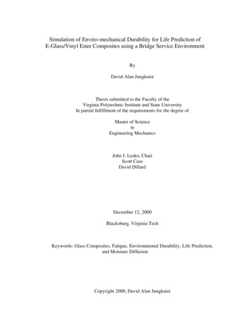
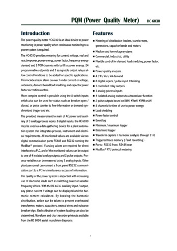
Approach: Novel Power Electronics Concepts ExploredSiC TransistorDeviceSoft SwitchingHigh Current DensityPackageHigh Temp PackagingNovel y/LifeTask 1:VA Tech SoftSwitching PowerModuleNovel SubstratesTask 2: DelphiHigh CurrentDensity IGBTPackageDouble Sided CoolingTwo-phase coolingETM ModelingTemp/Vgs as healthmonitorTask 3:NREL CoolingAzure Dynamics8
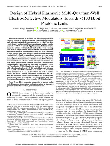
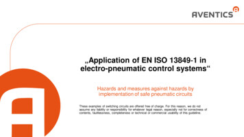
Approach: Electro-Thermal SimulationThermalModel Electrical and thermal templates foreach component are developed TJG1S1THTCElectricalModelTA Electrical Si IGBTs Si MOSFETs Si PiN Diodes Thermal Die Die Attach DBC Layers Baseplate Ambient The power dissipation in the electricalcomponents will provide the heat for thethermal template input nodes. Thermal models are validated using NISThigh speed transient thermal imaging (TTI)and high speed temperature sensitiveparameter (TSP) measurementtechnologies.Azure Dynamics9
Thermal Network Component Modeling n3Azure Dynamics10
High Speed Temperature Sensitive ParameterMeasurement MethodAzure Dynamics11
Approach: Electro-thermal-mechanicalmodel of a generic IGBT module An electrothermal model is created of the IGBT modulewhich is used to determine the heating and cooling of thedevice during power cycling. Thermomechanical stress modeling is conducted usingUniversity of Maryland physics-of-failure models to assessdegradation in the package structure (die attach, DBCsubstrate) as a function of cycling. This degradationmanifests as an increase in the thermal resistance of thedamaged layer. The simulated junction temperature rise resulting fromincreased thermal resistance will be validated against actualjunction temperatures measured after temperature cyclingusing unique NIST variable speed thermal stress andmonitoring measurements. Also C-SAM, SEM, and X-rayimages of the package will be used to correlate the physicalattach damage to the measured temperature increase. The higher junction temperature rise will then be used todetermine the heating and cooling of the device as well asto serve as a monitor for the health of the packaged device.Azure Dynamics12
Approach: Physics of Failure Models forPower Electronic Module Degradation Wirebonds – primary failure site for power cycling– Wire flexure fatigueε (R ρ f )dψρ iψ i (r ρ f )dψρ iψ i r(ψ i ψ f )ρ iψ i r(κ i κ f )[1] Die attach –primary failure site for narrow temperaturerange thermal cycling– Attach fracture and fatiguebfecfpEnergy U e W p Wc U e 0 N W p 0 N Wc 0 Ndfc[2] Substrate – primary failure site for wide temperaturerange thermal cyclingda– Substrate fracture and fatigue A( K ) ndN– Copper delaminationAzure Dynamics13
FY 10 Accomplishments Task 1:– Semiconductor Models Developed for IGBT Soft Switching devices.– Electro-thermal Models Developed for IGBT Soft Switching package. Task 2:– NDA signed with Delphi in March 2010.– Electro-thermal modeling of Delphi module initiated. Task 3:––––Physics-of-failure models identified.Initial time to failure calculations for attach completed.Accelerated testing protocol developed.Model validation underway. Demonstrated ability to use TSP to monitor damage Demonstrated failure in same time frame as simulation Demonstrated calibration of junction temperature rise to packaging damageAzure Dynamics14
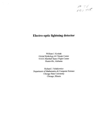
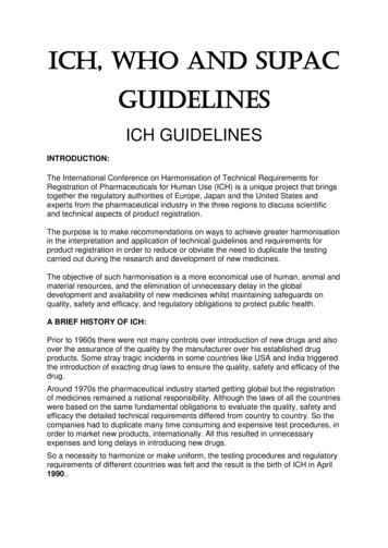
Previous Validation of Electro-thermal Device Models for DiodesSi PiN DiodeMeasured125 oC100 oC75 oCSimulated160.0140.0120.0150 oC100.080.025 oC60.040.020.0MeasuredSimulated4.025 oC3.02.050 oC75 oC100 oC175 oC125 oC150 oC1.00.00.00.00.51.02.01.52.50.0 0.1 0.2 0.3 0.3 0.5Diode Voltage [V]Comparison of measured (dased) simulated (solid) outputcharacteristics at 25 oC, 50 oC, 75 oC, 100 oC, 125 oC, 150 oC and175 oC for a 600 V, 6 A Si PiN diode.Si CoolMOS Body Diode100.090.080.070.0250.0T 75 oCMeasured125 oC100 oC75 oC50 oC150 oC200.0Diode Current [A]Simulated60.050.040.030.020.00.6 0.7 0.8 0.9 1.0 1.1 1.2 1.3 1.4 1.5Diode Voltage [V]Comparison of measured (dased) simulated (solid) outputcharacteristics at 25 oC, 50 oC, 75 oC, 100 oC, 125 oC, and 150 oCfor a 600 V, 200 A Si PiN diode.Diode Current [A]5.0o25 C10.00.0150.0SiC JBSDiodeDiode Current [A]180.0SiC JBS Diode6.0Diode Current [A]200.0CoolMOS-Diode100.0Si PiN Diode50.00.00.20.40.60.81.01.2Diode Voltage [V]Comparison of measured (dased) simulated (solid) outputcharacteristics at 25 oC, 50 oC, 75 oC, 100 oC, 125 oC, 150 oC and175 oC for the body diode of a 650 V, 60 A SiCoolMOS.0.00.00.51.01.5Diode Voltage [V]2.02.53.0Comparison of forward characteristics for 650 V, 60 A SiCoolMOS anti-parallel diode; 600 V, 200 A SiC JBS diode; and600 V, 200 A Si PiN diode at 75 oC.Azure Dynamics15
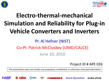
Electro-thermal Simulation:Soft-Switching Vehicle Inverter61 WAuxiliary Switch (Sx1)106 WMain Switch (S1)Freedom Car SoftSwitching InverterElectrical Circuit ModelElectro-thermal simulation of junction temperaturefor switches undergoing half-sine wave power cycle.Electro-thermal modeling permits the determination of both the junctiontemperature (blue lines) and the low frequency thermal cycling parametersfor the bottom of the chip (black lines) when the surface of the chipundergoes high frequency power cycling.Azure Dynamics16
Accelerated Testing for Electrothermal-mechanicalModel Validation: Protocol Developed Fully characterize module architecture (materials and geometry).Procure between 3 and 10 samples for each test.Conduct initial analysis and validate layout and stack-up. C-SAM for cracking; X-ray for void growth; Cross-sectioning for damageDetermine temperature cycling conditions.Determine stress/strain on the sample for each temperature cycle.Conduct initial time-to-failure calculation.Conduct temperature cycling using NIST variable speed thermal stress cycler.Monitor for TSP using 450 W pulse for 10 ms at 30 cycles, and then in 100 cycle intervals.Convert TSP to temperature and plot T vs. number of cycles.Take sample out periodically for analysis. (C-SAM, X-ray, Cross-sectioning)Identify degradation points at various percentage increase in temperature.Incorporate thermal degradation model into electro-thermal model.Validate degradation mechanism using results of the physical damage analysis.Model electrical performance parameters as a function of cycling time.Azure Dynamics17
Development of Electrothermal-mechanical Model:Initial Time to Failure Calculations Using PoF ModelsTesting Condition: SiC MOSFET, SiC antiparallel diode, Si series diode100 µm thick Sn37Pb eutectic die attachTemperature from 25 C to 200 C, 20 minute cycle10 min hold at 200 C, 5 minute ramp up, 5 minute ramp downPredicts failure should be observed around 900-1300 cyclesUsing Strain-Range Approach for Sn37PbEutectic SolderUsing Norris – Landzberg for HighLead Solder Die Attach30CPH 0.33e (1.87 0.0134 Tmax )2( γ )L α Twhere γ 2tNf 0.5( γ/2εf)1/cN c -0.442 – 6 x 10⁻⁴ Tsj 1.74 x 10⁻² ln(1 (360/td)) SiC MOSFET is 8 mm x 8 mm γ 0.0198 1240 cyclesSiC antiparallel diode is 4mm x 5mm γ 0.0112 4440 cyclesSi series diode is 10mm x 8 mm γ 0.0224 940cycles SiC MOSFET is 8 mm x 8 mm γ 0.0198 1266 cyclesSiC antiparallel diode is 4mm x 5mm γ 0.0112 3956 cyclesSi series diode is 10mm x 8 mm γ 0.0224 989 cyclesAzure Dynamics18
Measured Increase in Tj Resulting FromTemperature Cycling of a SiC MOSFET Module47.6820.0046.68ΔT 039.680.1110100% Temperature IncreaseC-M-37-3, 450W, 10msMax Temp vs. Thermal Cycles1000Cycle Count Device surface temperature (Tj) is measured periodically during thermal cycling using HighSpeed Temperature Sensitive Parameter Method Increase in temperature after 500 cycles indicates substantial packaging damage(potentially die attach fatigue).Azure Dynamics19
Thermal Simulation is Used to Correlate T with Decrease in Interface ConductionChipCuAlNCuThe decrease in die attach thermal conductivityleads to an increase in the junction temperatureof the device similar to that seen experimentally.Cu30.00 T Increase %25.00 T Increase % Die attachsolderconductivityfractionAs the package undergoes thermal cycling, thedie attach degrades, decreasing its thermalconductivity.(%k0) 20.0015.0010.005.000.00100806040200Fraction of Undamaged Die AttachConductivity (%k0)Azure Dynamics20
Collaborations– NIST – (Government) – Electro-thermal models forsemiconductor devices, packages and cooling; simulationfor vehicle application conditions.– University of Maryland (CALCE) – (Academic) – Providingreliability models to assess the degradation of packagingmaterials with time.– Virginia Tech – (Academic) – Leads team providing lowthermal impedance, high voltage SiC hybrid soft switchingmodule for performance and reliability analysis at 105 C.– Delphi – (Industrial) – Providing a double-sided-coolinghigh current density IGBT package for performance andreliability assessment at high current density.– NREL – (Federal Lab) – Developing and assessing coolingtechnologies for improved performance and reliability for105 C coolant conditions.Azure Dynamics21
FY10 Approach and gSepTask 1Validated Semiconductor Modelsfor Soft Switching ModuleDemonstrate Module OptimizationValidated Thermal Model forLow Thermal Impedance Soft Switching ModuleTask 2Task 3Dynamic electro-thermal model forHigh Current Density IGBT PackageMaximum Safe Current Densityversus use and fault conditionsPoF Model DevelopmentAccelerated TestDevelopmentTestProtocolArticleAccelerated TestingAzure Dynamics22
Future Work FY10– Incorporate thermal stress modeling into dynamic electro-thermal models– Demonstrate Dynamic Electro-thermal Model for High Current Density IGBT Package– Identify maximum safe current density vs. use and fault conditions in High CurrentDensity IGBT Package– Document a series of metrics for in-situ monitoring in test and in the field that can beused to quantify the effects of the package degradation on the thermal and electricalperformance of a generic module. FY11– Perform detailed optimization analysis for low thermal resistance, soft switchingmodule.– Develop thermal network component model for air cooling system.– Develop electro-thermal models for advanced semiconductor devices including SiCMOSFETs and SiC JFETs.– Develop electro-magnetic package/system interconnect models. FY12– Include impact of air cooling and advanced semiconductors in optimization of lowthermal resistance, soft-switching module.– Perform EMI simulations using electro-magnetic package/system interconnect models.Azure Dynamics23
Summary The need for increased power density in advanced vehicle power electronicmodules is leading to the development of new materials, devices, circuittopologies (VA Tech), packaging structures (Delphi), and cooling strategies(NREL). The effects of these new technologies on the performance and reliability ofpower electronic modules must be examined and designs optimized. Dynamic electro-thermal models and physics-of-failure models (UMD) basedon thermo-mechanical degradation, have been developed for nextgeneration power modules relevant to VT programs. Accelerated test protocols have been developed and are being used forvalidation of the models. Initial testing has confirmed increases in the temperature sensitiveparameter with cycling consistent with accumulated damage in the package. The models will be used to set and monitor device performance metrics andto develop standards to guide the reliable insertion of technologies into nextgeneration products.Azure Dynamics24
Delphi high current density IGBT package Perform stress and monitoring experiments and develop degradation models and accelerated testing protocols for Plug-in Vehicle package technologies to permit reliable operation with 105 C coolant and reduce testing cost: Stress ty