Transcription
„Application of EN ISO 13849‐1 inelectro-pneumatic control systems“Hazards and measures against hazards byimplementation of safe pneumatic circuitsThese examples of switching circuits are offered free of charge. For this reason, we do notassume any liability or responsibility for whatever legal reason, especially not for correctness ofcontents, faultlessness, completeness or technical or commercial usability of this guideline.
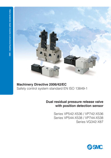
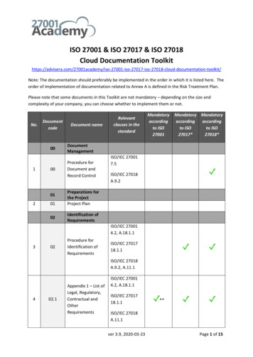
Circuit examples ISO 13849Technical Support Application 10/05/2016 circuit examples AVENTICSScope of EN ISO 13849 for pneumatic systems The area of valves in particular should beconsidered as „safety-related part of thecontrol system“, and specifically the valveswhich control hazardous movements orstates. The drive elements and components forenergy conversion and transmissiongenerally lie outside the scope of thestandard. Maintenance units for conditioning ofcompressed air must be considered from asafety perspective in conjunction with thevalve area. For possible energy conversions to becontrolled with consideration for safetyaspects, an exhaust valve is frequently usedin conjunction with a pressure switch.Source: BGIA Report 2/2008e Functional safety of machine controls2
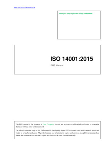
Circuit examples ISO 13849Technical Support Application 10/05/2016 circuit examples AVENTICSExample 1Stop of cylinder movement by pressurizingboth sides (Category 2), possible PL a-d In case of pressure drop, the non-returnvalves 1V2 and 1V5 avoid exhausting - cylinder is kept in position. The pressure regulator 1V1 reducessupply pressure so that there is a balanceof forces cylinder movement is stopped1 channel, 100-fold test of SF before need,0 failure safety between test phases Block diagram1V41V3 1S2Positive assessment by IFA3
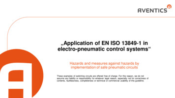
Circuit examples ISO 13849Technical Support Application 10/05/2016 circuit examples AVENTICSExample 2a4Safe retraction of a cylinder(Category 3), possible PL a-e The cylinder 1Z can be retracted by non-operatingof valve 1V1 or non-operating of valves 2V3 and2V1. On permanent operation of valves 2V3 and 2V1,the cylinder 1Z can be driven by valve 1V1. The retraction of the cylinder is redundant. Further safety function: redundant „avoidance ofunexpected start-up“, (category 3). Block diagram2V3
Circuit examples ISO 13849Technical Support Application 10/05/2016 circuit examples AVENTICSExample 2bProtection against unexpected start-up(Category 3), possible PL a-e The cylinder can be kept in initial positionwith both switching positions of valve 2V2. The cylinder can only be extracted withfull power by operating the valves 1V1,2V3 and 2V1. Block diagramPositive assessment by IFA5
Circuit examples ISO 13849Technical Support Application 10/05/2016 circuit examples AVENTICSExample 3Safe stop in upper position by clamping andone-sided pressurizing (Category 3,Category 4 attainable), possible PL a-e Clamping unit 2A can be released byvalve 2V with supply pressure at pressureswitch 2S1 and a control system 2S2. Non-return valve 1V1 avoids exhaustingon pressure drop. Block diagramPositive assessment by IFA6
Circuit examples ISO 13849Technical Support Application 10/05/2016 circuit examples AVENTICSExample 4Safe stop of a cylinder in upper position byclamping and one-sided pressurizing(Category 3, Category 4 attainable),possible PL a-e Approaching the upper end-position inbasic switching position of valves 1V3 and1V6. Clamping unit 2A which can be releasedby valve 2V with supply pressure atpressure switch 2S1 and a control system2S2. Block diagramPositive assessment by IFA7
Circuit examples ISO 13849Example 5Technical Support Application 10/05/2016 circuit examples AVENTICSSafe exhausting (Category 3), possible PL a-e The system is exhausted in the basic switchingposition of the valves, 2 paths for exhausting:1. Via non-return valves 2V2 and 2V3 and valve 2V1(the minimum opening pressure of the non-returnvalves is to be respected).2. Via valve 1V. Retraction and extraction of the cylinder is onlypossible with combined operation of 2V1. Block diagramPositive assessment by IFA8
Circuit examples ISO 13849Technical Support Application 10/05/2016 circuit examples AVENTICSExample 6 (BGIA Example 8.2.14)Protection against unexpected start-up of thecylinder (Category 3), possible PL a-e 2 possibilities to stop / hold the cylinder:1. On pressure drop and in the basic switching position of valve2V, the cylinder is held by clamping unit 2A.2. In closed (middle) position of the valve 1V1, the cylinder isstopped by blocking up the air. The cylinder can only be extracted or retracted by combinedoperation of 1V1 and 2V. At re-starting, check the pressure balance of the cyl. piston. Block diagramPositive assessment by IFA9
Circuit examples ISO 13849Technical Support Application 10/05/2016 circuit examples AVENTICSExample 7 (BGIA Example 8.2.25)Safe stop / holding by two-channel block-upof air (Category 3), possible PL a-e 2 possibilities for stopping / holding thecylinder1. For non-operation of 2V1, the valves 2V2and 2V3 are in closed position.2. For non-operation of 1V, the valve isclosed in mid-postion. Block diagramPositive assessment by IFA10
Circuit examples ISO 13849Technical Support Application 10/05/2016 circuit examples AVENTICSExample 8 (BGIA Example 8.2.25)Safe stop / holding by 2-channel block-up ofair extension (Category 3), possible PL a-e 2 possibilities for stopping / holding the cylinder1. On non-operating of 2V1, the valves 2V2 and 2V3 are in closedposition.2. On non-operation of 1V, the valves is closed in mid- position.Extended options: Release of pilot air for 1V and compressed air supply for 2V1 byoperating 0V1. Controlled start-up by filling unit 0V3. Block diagramPositive assessment by IFA11
Circuit examples ISO 13849Technical Support Application 10/05/2016 circuit examples AVENTICSExample 9Safe stop / holding by 2-channel block-up ofair (Category 3), possible PL a-e extensionStop / Hold the cylinder On non-operation of 1V5, the valve is in closedmid- position. If 2V2 and 2V3 are operated, the valve 1V1 closesup in mid-position.Extended option: targeted exhausting on pressuredrop during setting mode, e.g. for rescue ofpersons by switching 1V5. Block diagram1V12V1 2V2 2V3 1V4 1V52S121S21S3
Circuit examples ISO 13849Technical Support Application 10/05/2016 circuit examples AVENTICSExample 10Safe stop / holding by 2-channel block-up ofair (Category 3), possible PL a-e extensionStop / Hold the cylinder Close up via valve 2V6 and non-return valve 2V10. On non-operation of 1V1, the valve is closed in midposition.Exended option: Targeted exhausting on pressure dropby switching 2V6 and controlled movement of thecylinder into start-up position by one-sided throttledpressurizing via 2V8. Block diagramPositive assessment by IFA13
Circuit examples ISO 13849Technical Support Application 10/05/2016 circuit examples AVENTICSExample 12Avoid unexpected operation by blocking uppilot air (Category 3), possible PL a-eBlock-up of pilot air The pilot air is blocked through 2V inbasic switching position, the valve 1V1cannot be operated. Block diagramPositive assessment by IFA14
Circuit examples ISO 13849Technical Support Application 10/05/2016 circuit examples AVENTICSExample 13Avoid unexpected operation by blocking uppilot air safe stop/holding by two- channelblock-up of air (Category 3), possible PL a-eBlock-up of pilot air1. In the basic position, the pilot air is blocked through2V, the valves 1V and 3V1 cannot be operated.Block-up of air2. On non-operating of 3V1, the valves 3V2 and 3V3 arein closed position.3. On non-operating of 1V, the valve is closed in midposition. Block diagram3V13SPositive assessment by IFA153V23V3
Circuit examples ISO 13849. Example 13. Avoid unexpected operation by blocking up pilot air safe stop/holding by two- channel block-up of air (Category 3), possible PL a-e. Positive assessment by IFA. Block-up of pilot air. 1. In the basic position, the pilot air is blocked through 2V, the valves 1V and 3V1 cannot be operated. Block-up of air. 2. On non-operating of 3V1, the valves3V2 and .