Transcription
JElectro-opticlightningWilliamJ. KoshakGlobalHydrologyNASAMarshall& erCenterAlabamaJ. Solakiewiczof MathematicsChicagodetectorStateChicago,& ComputerUniversityIllinoisScience
AbstractThe design,described.alignment,The primary(KDP)electro-opticantennais exposed685 nm),light throughsensingcrystaloptics,electricthe opticaland field deploymentof the detectorthat is attachedin seriesandthundercloudthefield changescell. Severalduring five thunderstormsSpace Flight Center (MSFC)of a solid-statecomponentto the on,crystalelectricareis a potassiumto a fiat platearrangedthat occurredin northern Alabama.lightningaluminumin a Pockelselectricin the summerdetectordihydrogenfield. A semiconductorare related to small changeshundredlightningisphosphateantenna;thelaser diode (2 cellconfiguration.in the transmissionfield changeof laserexcursionsof 1998 at the NASAwereMarshall
1. avingtimesthe pointof fleein theshouldbe in tThe decayForassuresthe "zeroline"and dynamicvaluesThelooprangeof 4 s, 0.3ms,antennaintegratingto the plateoutputplateR andfieldusedplatemustcomposedbeinput(slowtheof anC in parallel.and the noninvertingin secondsnormalto measurecircuitcapacitorare measuredtheA is integratingelectricintegratinginducedin thea resistorin thunderstorma chargeQ is thea changeTheis grounded.antennas)andantennas).of the experimenter,[1].andof an electronicis attachedbe in millisecondsfromamplitudecharge.of the electrometerantennawherespace,feedbackchangesof an exposedE,, Q/(A o),of interestthe RC shouldmetalsurfacenormallyof viewvariationlightningat theto microsecondsfields,occurs;plateof the electrometermillisecondstimeof a flatin inducedchargeRC decayFromlightning-causedpermittivitya changeandinputE,,for measuringconditionin inducedinvertinganyfieldis e RC decayinstance,if onein totalsensoroutputof the sensorto the event.70/3s tolookfieldis nullifiedbecausebe madein lightninglightningis an advantageandshouldis interestedand if interestedthat thetimeat variousreturnchanges,beforeone can devoteThelargeranotherthethanstrokethe RCeventfull verticalsystemsdescribedby [2]temporalregimesin thesignature.In thetechnologiesinvestigationspast20 years,havewerearisenseveralnewfor ardandcommercialvoltagesthe studyand fieldsapplications([3]of thunderstorm- [10]),of electro-opticand someelectricfields.of these
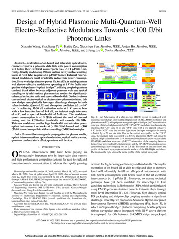
Electro-opticintensitycrystalsor phase of opticalhigh-speeddigitalBecausethe crystalsrespondfrequencieshigh speedopticala convenientand affordablein an rdeflection,to appliedof several gigahertzshuttervoltagesare possible.recentlyof controllingof applicationsand spectraltunableand no movingpartsLiquid crystalsthethat includefilters[11].are required,have also been used inand [12] has used liquid crystalsstudy, we describedeveloped(MSFC)fabricatedand deployedin Huntsville,electro-opticin the summerThe sensorcomponents,during deploymentcomponentscrystalto measure"KDP"for brevity);detailsof the design,alignment,is an sdeployment,the design characteristicsof the lightningFriedrichmodulator.of bothon a small laboratorystrokesset to a fewin a lightningwrittenflash.high impedanceas KH2PO 4, orin [13].Thebelow.effect since it is fundamentaltodetector.was the first to describe([14], [15]). FigureThe centralFlightEffectPockels (1865-1913)early publicationsSpaceand data results are discussedwith a review of the linear electro-opticthat wasmodel composedof KDP are providedWe begin our discussion2. The Linear Electro-OpticMarshallplate and a long cylindrical,phosphateand opticalcalibration,detectorfrom 1 s to 1 ,us and was typicallyin order to resolvedihydrogensome dielectricfield changeand the optics were mountedare a flat aluminumof potassiumlightningof 1998 at the NASAThe RC decay was adjustabletens of millisecondsThe main sensingan electro-opticAlabama.and vendor-suppliedoptical breadboard.opticmeansfield changes.In the trichave offered1 shows a typicalcomponentthe linear electro-opticPockelsis an electro-opticcell arrangementcrystal,KDP. Lighteffect in twofor an electrofrom a diode
laser(inputbeam)passesthroughtwo polarizers,a with a em.Equationsfor the transmissionof light throughan anisotropicmediumsuchas the KDPcrystalmay bederivedfrom tycr isnegligiblefor the materialsmagneticinductionwe are using at optic frequencies.B are related throughVxF -3B/Ct,whereF andused "F"and magneticto denote the laser light electricavoid confusion,i.e., "E"antennavectorJ is current density,B IJ.plate as suggestedThe electricinto diagonalmagneticform by a suitablepermeabilityEnergypermittivityof a vacuum,conservationis describeddenotethe (enhanced)for anisotropicof coordinates.pfi is the outwardandJnormalare both zero.perrnittivitySuitabletensorfor all materialsmaterials;we have"E"tofield at thethat follows.]TheI) o . F andit may be brought/ bykt,,, thein the optical circuit.byto a surface S whichThe equationfor energy.[,,,bounds a volumeconservationv. We will assumeof ( 1) for isotropicmedia yield a wave equation k')r 0thatcan be used to show that theis symmetric.manipulationsnotationatmosphericWe will approximatex. -,,i,vwhere[Note:density, and we have the relationsis a tensorrotation(1)respectively.1 above and in the discussioncharge{D andV.B 0,field here rather than the customaryin sectionp denotesV-D p,field intensities,and its componentssensordisplacement[ 16]VxH OD/Ot J,I-I are the electricThe electric
The same equationpolarization,denotedis satisfiedk kl ,by H. Plane wavek 2 r/2,and1 is the directionf)e ikr-j are admitted, whereof propagation.by co, t is time, r is a position vector, and 2 is the wavelength.wave forms for F andI) - (k x H)/coH in anisotropicmedia,We let k con/c,a coordinateis diagonal.general, there will be two nontrivialThe followingpositive.coordinateverticalplaneH (k x F)/(co/t)andY, and X is chosenthe presentof perfectlyalignedLater however,the (x, y, z) system,or "crystalequation.will be alongon whichIna right-handedaxes when no voltageoptics,system.system",of misalignedwill be orientedconsideredareweto the crystal;thebetweenoptics provideddifferentlyasFurthermore,is placed across the crystal.there will be no distinctionin our discussionthe path ofthe componentsto the (X, Y, Z) system but is attachedprincipalsystems.and c is the speed of light, and refer tobreadboard,to completethe crystaldiscussion(4)from the laser to the photodetectorto the optics(x, y, z) system definesthe twoin sectionthan the fixedIn4,(X, Y, Z)system".indicesgeometrically.With such assumedsolutions.define a system (x, y, z) that is identical"breadboardisF.system will be used. The Z-coordinatedirectionwill definecoordinatefrequencyThe form in (4) is that of an eigenvaluelaser beam with the directionThe zenithmounted,- k2F -co2 t .where n is the wave index of refractionsystem in whichthe collimatedwe have the relationsAngular1 is afrom which we may obtain (see [17])(k. F)kThesolutionsof refractionBy consideringand theirsurfaces2x /n xassociatedof constant2 y2/ny2allowableenergy density, zY ? 1polarizationsmayan index ellipsoidbe obtained
maybe constructed[11];n x, n ,, andThe allowablepolarizationsellipseby the intersectionformedn: are the refractiveand indices of refractionindicesalong the coordinatemay be obtainedof the index ellipsoidaxes.by finding the axes of theand a plane normalto the directionofpropagation.The indexellipsoidof the crystalcrystal. The general formulamay be modifiedby applying2 (ny -2 r2kek)y2 (nz -2 r3kek)z 2rdkekyz 2rskekxz 2r6kekxythe summationelectricconventionhas been employed.field, and the rik are the electro-opticmodulatingfield be alongWe assumecoordinatenumericalcoefficientsof the crystal.so that its axesaxes. The KDP crystalis uniaxialwhichis defineda(- i )/-q/2fieldhaving a voltageIt is intendedthat theof symmetryare parallelthat n x n v n o , whereto then o has aThe extraordinaryn,, n o the KDP is additionallyindexspecifiedascrystal.eis appliedand (i )/, f2.these polarizations,of the applied1 j 5 for KDP.index of refraction.by n,, n 1.467. Sinceuniaxialmeans(6) 1,; only r63 is needed since rj3 0,value of 1.507 and is called the ordinary2ek are componentsis alignedbeing a negativeWhenThethat the crystalof refractionfield to theis given by [1 1](nx -2 rlkek)xwherean electricalongtheLight polarizedz-direction,alongthe waves along which propagateV e d,theallowed)' upon enteringat differentpolarizationsthe crystalspeeds. For a crystalareis split intoof length dthe phase lag isF c[G( 0n )" d ---- n2rc 3r63V- ,(7)
where n.,.(slow)Waves travelingordinaryandn l (fast)are the indicesalong the z-axiswith no modulatingindex. Waves travelingdetermineda variableindexphase retardationThe linear relationshipalongvoltageprovidedof the crystal.betweenIf the laser light field immediatelyfollowingin the z-directionThe crystal'sthe two wavesin (7) is the Pockelsthe allowedpolarizations.have a speed correspondingin the xy plane with polarizationby the extraordinaryintroduceof refractionutilityin responseto thehave a speedlies in its abilityto an appliedtovoltage.effect [ 18].the first polarizeris F 0 coscot Y, then the fieldof the output beam will beF F0[cos(cot - r) cos cot]: /2.Here,the phaseReflectionlossessolutionsat thethat accountUsingaveragechangedue to theinterfaceslengthbetweenare relativelysmall,for such losses are available(8) to obtainthe squareof F 2 [21]. Dividingoptical transmissionpathmagnitude(8)opticalcomponentsand are customarilyis suppressed.neglected.Exact([19], [20]).F 2, the powerby the input power,whichis obtainedis proportionalby takingto F02/2,the timeyieldstheT given by(9)T sin 2 F/2 sin2[(TcV)/(2V )],wherewhichV, 2/(2n3r63)iscalledvoltage,i.e., V V yieldsa retardationof rcis one half of 2 r, or "one half wave".Note that the derivative,no voltagetransmissionT'(0)the half-waveT'(V)across the crystal,with appliedis as largei.e.,voltageas possible.- dT/dV,T'(0) or electro-optic0.In order to have the largestfor small voltages,Thismaysensitivity,it is convenientbe achievedis zero when there ispossiblechangeinto start at a point whereby introducingan additionalphase
retardationofre/2 by insertingthe transmissiona quarter wave plate before the secondpolarizer.In such a case,of the system is given byT sin2[F/2 Tc/4].This processis the optical analog of biasing an electronicThe precedinganisotropicdiscussionmedia.has summarizedSome early experimentalNote from (9) and (10) that a high frequencyvary the opticalthe PockelsHowever,the opedtherebyinvestigationsmodulationelectro-opticof this effectvoltageamplitudeeffectare providedcan be appliedinin [22].to the crystalof the output beam.cell can also be used in the reversevoltage.in the optical amplitudetoIn this senseprincipleplaces a transientthe optical transmissionsense,thatis, a high gainof the output beam can be used to inferThis is the operationalin this work. The lightningchangingof the linearcan serve as a high speed optical shutter.of small changesin crystalcomponent.the basicsand hence the opticalcell configurationthe changes(10)of the electro-opticvoltageof laser light throughlightningacross the electro-opticthe cell. Specificdetailsof the sensor follow.3. SensorDescriptionFigure 2 providesNASApointedMSFC. The detectorobjectsthunderstormthatseparatesin the atmosphereovervieware depositedof the electro-opticis placed outside on a flat surfacecouldpositiveproduceof negativelocaland negativeand on the ground.2, tens of coulombsaltitude)a simplisticchargefield-limitingchargescoronaand therebyfrom the lower regionstransferdetectorsufficientlyWhen a cloud-to-groundto Earth. The large chargelightningatfar from tall grass ordischarges.generatesNotestrong electricflash occurs,thatafieldsas shown in Figureof the thundercloudis accompanieddeveloped(i.e., -7 kmby a substantialchange
in theelectricfield AEg at theground,i.e.,a AEg 5 kV/m is not uncommonfor dischargesthatarewithin a rangeof a few kilometers.Thoselightningeventsthatdo nottransferchargetogroundbut transportchargewhollywithin the atmosphere,calledcloudsubstantialvaluesof AEx. In general,from that at the ground,Figure 2 indicatesproducesa change in crystal voltageWhenthe sensorfrom the opticalInc. currentsystempreamplifierdetectsA iderablyopticaldiscussedbeamis passed to a PentiumcomputerA/D board (modelin Figurein section 2. The designsdivergenceDT2833).3(a); it is based on theof optics are mountedTheintent"on-line"of the sensorcould be precisionwason anto buildadjustabilitywouldmountedandbe scaledwithinadowna singlelong and wide).is a 30 mW semiconductorof 685 nm and an elliptic beam cross sectionThe beam height above the opticalis negligibleacrossthelengthofare to allow the laser a few minutes10thelaser(major and minor axesWe have also used a 4 mW, 670 nm laser diode,sensitivity.during neering1 mm, respectively).of reducedconsiderationsis providedfrom left to right in Figure 3(a), the first elementof 4 mm andthesystemthe photocurrentusing a Stanfordcm in dimension.diode that has a wavelengthan
Electro-optic lightning detector William J. Koshak Global Hydrology & Climate Center NASA Marshall Space Flight Center Huntsville, Alabama Richard J. Solakiewicz Department of Mathematics & Computer Science Chicago State University Chicago, Illinois. Abstract The design, alignment, calibration, and field deployment of a solid-state lightning detector is described. The primary sensing component .