Transcription
Trends In ESD Test MethodsbyStan WeitzElectro-Tech Systems, Inc. (ETS)(Materials Testing Section of the ETS Testing Laboratory)When asked, “What’s new in ESD Test Methods” the answer is plenty. Over the past decade the static controlindustry has come a long way. As new technologies develop, ESD susceptibility levels drop (in the hard driveindustry ESD susceptibility levels are down to an incredible 5 volts).Electrostatics is as old as time itself. It was not until 600 BC that Thales of Miletus began conducting basicexperiments with static electricity that involved charging Amber by rubbing it with a piece of fur and observing theattraction of lightweight objects such as fur, feathers, etc.Serious work in the field of electrostatics began during the Renaissance when Gilbert published DeMagnete in theyear 1600. Over the next several centuries, experimental work by Gauss, Coulomb, Faraday and Franklin establisheda solid basis in the knowledge and understanding of electrostatics.In the latter part of the 19th century the interest in electricity shifted from electrostatics to electrodynamics (batteriesand generators). Except for the invention of systems like the electrostatic precipitator for cleaning industrial smoke,electrostatic air filters for cleaning the air in enclosed environments and ionizer bars to control the build up of staticelectricity during the manufacture of textiles and paper, electrostatics was generally relegated to the classroom andto spectacular demonstrations in science museums.More Recent HistoryThis situation began to change after WWII with the appearance and increasingly widespread use of polymeric,highly insulating materials such as polyethylene, polypropylene, polyvinyl chloride (PVC), etc. The manufactureand handling of these products became a problem, especially in dry locations. Large static charge accumulationsresulted in machinery shut downs, explosions and fires.
It was not until static electricity began to impair the reliability and operation of electronic equipment that electrostatic phenomenon began to be taken seriously. With the development of Metal Oxide Semiconductor (MOS)technology in the 1960s, the effects of an invisible static discharge (levels below 2000V) were finally realized.Initially, static control procedures consisted of shorting the device leads together during shipment, using carbonloaded packaging or shorting bars, and grounding workers who were handling the devices. By the late 1960s, themilitary began to define the electrostatic characteristics of materials and to specify their use in specific applications.In 1969, Method 4046 “Electrostatic Properties of Materials” was incorporated into Federal Test Method Standard101. Shortly thereafter, MIL-B-81705 “Barrier Materials, Flexible, Electrostatic-Free, Heat Sealable” was issued.For the first time a specification and a test procedure defined the electrostatic performance of materials underspecified test conditions for specific applications. Over the next decade, the military generated MIL-HDBK-263“Electrostatic Discharge Control Handbook for Protection of Electrical and Electronic Parts, Assemblies andEquipment” and MIL-STD-883 “Electrostatic Discharge Sensitivity Classification”.Resistivity had always been considered a key parameter in specifying a material’s “antistatic” properties. ASTM-D-257 “DC Resistance or Conductance of Insulating Materials” and ASTM-D-991 “Rubber Property-VolumeResistivity of Electrically Conductive and Antistatic Products”, were issued in 1925 and 1948 respectively by theAmerican Society for Testing and Materials. These test methods were widely used to define and measure“antistatic” material. Today, “Antistatic”, as defined in the EOS/ESD Glossary of Terms, refers to the ability of amaterial to resist tribocharging and is NOT a function of Resistivity.Carbon loaded conductive material can generate a higher triboelectric charge on some materials, such as epoxy ICpackages, than a chemically treated plastic that has a much higher surface resistivity (103 versus 1011 ohms persquare). The resistive property of material defines its ability to dissipate charge. A materials antistatic propertydefines the ability to resist being charged triboelectrically.By the late 1970s , military and industry began working together to address the far reaching effects of staticelectricity. Over the past two decades, the war against ESD has come a long way. From its origin as a disorganizedarray of static control methods and products there has emerged a sophisticated approach to static control involvinggovernment, academia, suppliers and users. One of the most important contributions to static awareness was theestablishment of the ESD Association along with the formation of special task groups within the military andestablished industry associations such as the EIA (Electronics Industries Association), ASTM (American Society forTesting and Materials) and the IEEE (Institute of Electrical and Electronics Engineers).Through the ESD Association, symposia have been held every year since 1979 where static awareness, failuremechanisms, test methods, static control techniques are discussed and new technologies to control ESD arepresented. The Association has recently become an ANSI (American National Standards Institute) recognizedorganization for developing ESD test methods and standards. Other organizations can now incorporate theseaccredited ESD Association Test Methods directly into their own standards. Table 1 lists the principal ESDstandards and test methods.Since the early days of static control, many new products have been developed, but the available methods to testthese products were limited. It became obvious that new standards and test methods were needed and existing oneshad to be modified to better define what could and could not be tested. This is illustrated by specification EIA-541“Packaging Material Standards for ESD Sensitive Items”. This standard was eight years in the making when it wasfinally issued in 1988. Even as the final revisions were being added plans were underway to upgrade many of its testprocedures. At the present time, this work is being carried on by ESD Association standards committees.
STANDARDSEOS/ESD S1.0ESD DS1.1ESD STM2.1ANSI/EOS/ESD S3.1EOS/ESD S4.1ESD DS4.1ESD STM4.2ANSI EOS/ESD S5.1ANSI ESD S5.2ES DESD DS5.2ESD DS5.3ANSI EOS/ESD S6.1ANSI ESD S7.1ANSI ESD S8.1ESD S9.1ANSI EOS/ESD DS11.11ESD DS11.12ANSI ESD S11.31ESD STM12.1ESD ADV 1.0ESD ADV 2.0ESD ADV 3.2ESD ADV 11.2ESD ADV 53.1WIP 2.2WIP 3.3WIP 5.3.1WIP 5.4WIP 10.1WIP 10.2WIP 11.13WIP 11.14WIP 11.32WIP 13.1WIP 14.1WIP 53.2WIP 54.1WIP 54.2WIP 55.1WIP 2020ASTM D-257ASTM D-991ASTM D-2679ASTM F-150AATCC-134CECC00015EIA-541IEC 801-2MIL HDBK-263AMIL-STD 883DMIL-STD-1686AMIL-B-81705CFTS Method 4046ISSUES ADDRESSEDPersonnel Grounding Wrist StrapsE valuation, Acceptance & Functional Testing of Wrist Straps (Revised)Resistance Test Method for ESD Protective GarmentsIonizationWorksurfaces - Resistive CharacterizationWorksurfaces - Resistive Characterization (Revised)Worksurfaces - Charge Dissipation CharacteristicsESD Sensitivity Testing Human Body Model Component LevelSensitivity Testing Machine Model Component LevelESD Sensitivity Testing Machine Model (Revised)ESD Sensitivity Testing Charged Device ModelGrounding - Recommended PracticeFloor Materials - Resistive Characterization of MaterialsESD Awareness SymbolsResistive Characterization of FootwearSurface Resistance Measurement of Static Dissipative Planar MaterialsVolume Resistance Measurement of Static Dissipative Planar MaterialsE valuating the Performance of ESD Shielding BagsSeating – Resistive CharacterizationGlossary of TermsESD HandbookSelection of Acceptance of Air IonizersTriboelectric Charge Accumulation TestingESD Protective WorkstationsGarments. Field AttenuationIonization, Periodic Verification of Charge Generation CharacteristicsDevice Testing, Charged Device Model, SocketedDevice Testing, Transient Latch-UpAutomated Handlers, Resistive MeasurementAutomated Handlers, Charge GenerationPackaging – 2 Point Resistance TestPackaging – Bulk Loose FillElectrostatic Shielding – Corrugated MaterialsHand Tools – Soldering IronsESD SimulatorsWorkstations, Related Storage EquipmentFlooring/Footwear Systems, Resistance in Combination with a PersonFlooring/Footwear Systems, Voltage Accumulation on a PersonClean Room OperationsConversion of Mil-Std-1686 to a commercial document.Resistance or Conductance of Insulating MaterialsVolume Resistivity of Electrically Conductive & Antistatic ProductsStandard Test Method for Electrostatic ChargeElectrical Resistance of Conductive Resilient FlooringElectrostatic Propensity of CarpetsProtection of Electrostatic Sensitive Devices (Europe)Packaging Material Standards for ESD Sensitive ItemsElectromagnetic Compatibility for Industrial Process MeasurementHandbook for Protection of Electronic Parts, Assemblies & EquipmentElectrostatic Discharge Sensitivity ClassificationProgram for Protection of Electronic Parts, Assemblies & EquipmentBarrier Materials, Flexible, Electrostatic Protective, Heat SealableElectrostatic Properties of MaterialsTable 1
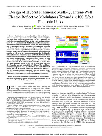
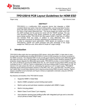
Measuring ResistivityOne of the most misused test methods for measuring static control material is Surface Resistivity Per ASTM-D257”. This method was originally developed for measuring the resistivity of insulating materials. The surfaceresistivity of an ideal material is constant across the surface, however, many static control materials such aslaminates and composites are neither insulating nor homogeneous and have bulk resistance properties. A laminatemay consist of a very thin surface layer having high surface and volume resistivities laminated to a much lowerresistance layer, however, the actual resistance measured through a thin layer may be low even though its volumeresistivity is high. When the surface resistivity of this laminate is measured in accordance with method ASTM-D257, a parallel resistance path through the material occurs resulting in a perceived low surface resistivity. What isactually being measured is the resistance through the material to the low resistance layer, across this layer, then backthrough the material. When this measured resistance is converted to surface resistivity by multiplying the measuredresistance by the electrode geometry, a significant error is introduced.This well-known problem was addressed when the test standard for static control worksurfaces was developed andissued in 1990 as EOS/ESD Standard S4.1 “Worksurfaces-Resistive Characterization”. Many static control worksurfaces are constructed as described in the laminate example above. In S4.1, resistance at defined locations betweentwo points and between a point and ground are specified using a defined electrode configuration and a defined testvoltage. Surface resistivity is no longer used to specify static control worksurfaces.EOS/ESD Standard S11.11 “Surface Resistance Measurement of Static Dissipative Planer Materials” was developedto address the problem with ESD protective packaging. A defined concentric ring electrode configuration that meetsthe criteria specified in ASTM-D-257 was selected to measure the surface resistance of planar (flat) material. Theresistance measured may be the result of surface only or surface and bulk resistance of the material. By defining thesize, weight and configuration of the probe, the test voltage, and performing the measurement under tightlycontrolled environmental conditions, inter-laboratory measurements accuracy was reduced from two orders ofmagnitude to better than one-quarter of an order of magnitude. Measurement accuracy is also greatly enhanced byspecifying an electrode alignment fixture and test procedure. Figure 1 shows a typical surface resistivity and surfaceresistance probe along with calibration check fixtures that meets both ASTM-D-257 and EOS/ESD S11.11requirements.Figure 1If the material being tested meets the criteria for ESD S11.11, the measured value obtained can be converted to anohms per square (Ω/sq.) value by multiplying the resistance by 10. This is due to the probe’s concentric ringelectrode geometry which results in a surface resistivity equal to ten times the measured resistance.
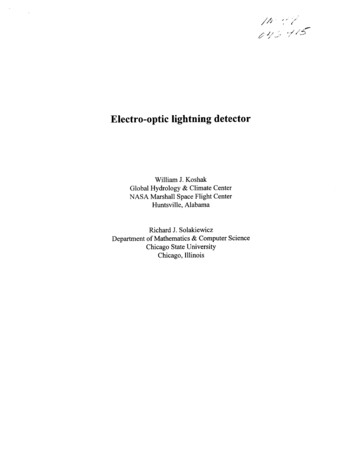
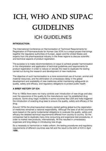
ESD Association Standard S 11.12 “Volume Resistance of Planar Materials” addresses a similar problem found inspecifying volume resistivity. Again, the resistance through the material using defined electrode geometry andspecified test procedure is used to characterize the volume resistance of ESD protective material.Other areas where resistance measurement uses a defined electrode configuration include ESD S7.1 and DS7.2 forflooring, S2.1 for garments, S12.1 for seating, and S4.1 for worksurfaces. These standards all use a five-pound probewith a two and a one half-inch diameter conductive rubber electrode. Figure 2 shows a typical probe.Figure 2EIA-541The static shielding bag was introduced in 1977, but no test method existed at that time to easily measure its staticshielding characteristics. A surface resistivity of less than 1 x 10⁴ ohms per square was specified but when theshielding layer is buried in the laminate there was no accurate way to measure it. In addition, the fact that the basicmaterial is static shielding does not mean that the final product provided effective shielding. The capacitive probetest was adopted into EIA-541 for verifying the relative effectiveness of static shielding bags. The main difficultywith this test method, however, was the latitude allowed in conducting it.A new test method, EOS/ESD S11.31-1992 “For Evaluating the Relative Performance of Electrostatic ShieldingBags” was developed to address the shortcomings in the EIA-541 test method. This standard measures the energydetected by a capacitive sensor placed inside the bag when the outside of the bag is exposed to a human body modeldischarge of 1000 volts. Areas addressed by this method are defining the discharge waveform and capacitive sensor,the use of a current probe to measure current through a specified resistance of 500 ohms, (in lieu of the dual voltageprobes used in EIA-541) and defining bag size (8” x 10”). With this test method, the energy resulting from thecurrent pulse, instead of the difference in peak voltage across the sensor, is calculated. Testing has indicated thatenergy can be correlated to device failure inside the bag.The oldest and most difficult test to perform is the measurement of the charge developed on material as a result oftriboelectric charge generation. Specifications still exist today using cat fur (MIL-P-19644C “Cat Fur”) and theattraction or repulsion of ashes or smoke. Two test methods are described in EIA-541: The first, evaluates theantistatic properties of device (IC) shipping tubes while the second references bags and pouches. In the first method,devices are slid through the shipping tube under test and into a Faraday Cup. The charge, not the voltage, developedon the device is measured in nanocoulombs.
When carefully performed the test can give reliable results. The second test uses quartz and Teflon disks that arebounced around inside a test bed during a defined shaking cycle and then dumped into a Faraday cup. This test isvery cumbersome and has been virtually abandoned.The test method that is currently used by most organizations is the modified incline plane test. This method was firstintroduced at the 1984 EOS/ESD Symposium and was subsequently modified several times. This method uses atwelve-inch plane inclined at an angle of 15 . Quartz and Teflon cylinders are rolled down a sample of materialmounted to the plane. The cylinder drops into a Faraday cup and the resulting charge is measured. Quartz andTeflon are used to represent material at both ends of the triboelectric series as seen in Table 2.TRIBOELECTRIC SERIESPOSITIVE ( )Human HandsRabbit FurGlass (Quartz)MicaHuman odAmberSealing WaxHard RubberNickel, CopperBrass, SilverGold, PlatinumSulfurAcetate nePolypropylenePVCKEL FSiliconTeflonNEGATIVE (-)Table 2This test method can also result in inconsistent measurements, however, if each test parameter is well defined andthe release of the cylinders down the plane is tightly controlled, repeatability and accuracy are greatly increased.This test and several other methods are described in ESD Adv. 11.2.
MIL-B-81705Mil-B-81705-B was upgraded in 1988 to Mil-B-81705-C. This specification incorporates transparent metallizedpolyethylene material and is designated as Type III. In addition, resistivity and capacitive probe shielding tests ofthe appropriate materials are specified along with static-decay. Since the capacitive probe test in this specificationreferences EIA-541, any future changes made to EIA-541 will affect Mil-B-81705-C (including resistivityrequirements). Although numerous commercial organizations reference this specification, compliance testing is onlyperformed for military applications.ESD Susceptibility of DevicesWork is being carried out to develop and/or improve standards for determining the ESD susceptibility of electronicdevices and equipment. The Military, the ESD Association, the IEEE and the IEC are performing this work.Mil-Std-883D defines the ESD sensitivity classification of devices used in military hardware. This standard has alsobeen generally adopted for commercial use. The waveform used simulates a discharge from a human body. Itdefines a model (HBM) of 100 pf discharged through 1500 ohms. Since its inception in 1980, the dischargewaveform characteristics have undergone numerous upgrades along with the way the waveform is applied to devicepin combinations. The latest version, Method 3015.7, requires the current waveform to be measured with a 350 MHzscope by discharging the HBM network directly to ground. The measurement is performed at 4,000 V. The rise timeis specified at 2 to 10 ns and the pulse decay time at 150 ns. Ringing is limited to 15 percent of peak.ESD Association Standard S5.1 “Human Body Model (HBM) Electrostatic Discharge Sensitivity Testing” providesa more comprehensive procedure for performing ESD susceptibility tests. Waveform verification is required for allvoltage steps used up to 8kV instead of only at 4kV as specified in MIL-STD-883D. A second calibration circuit isused where the current is measured through a 500 ohm resistor. This waveform must have a rise time of 5 to 20 nswith a pulse decay time of 200 ns.Two additional ESD models are the Machine Model (MM) and the Charged Device Model (CDM). The MachineModel, first introduced in Japan, simulates a discharge from a metal object. This model consists of a 200pf capacitordischarged through a zero ohm resistor. The Charged Device Model simulates a device that has become charged andthen is discharged to ground through one of the leads. Standards covering these models are ESD S5.2 and ESD S5.3respectively.ESD Susceptibility of EquipmentDetermining the ESD susceptibility of equipment is governed by a completely different set of standards. For humanbody discharge the military references MIL-STD-883D. For a discharge from a metal object held by a person theIEC 801-2 standard is most commonly used. The IEC (International Electrotechnical Commission) is anorganization made up of members from 40 different countries. IEC 801 “Electromagnetic compatibility forindustrial process measurement and control equipment” is a five part standard (with a sixth under development) thatcovers EMI, ESD, and Surge Voltage Immunity requirements for electronic equipment. Part 2: “ElectrostaticDischarge Requirements” covers electrostatic discharge directly to and in proximity of electronic equipment. Theoriginal IEC 801-2 (1984) specified an air discharge up to 15 kV whereby the ESD simulator was brought rapidlytowards the Equipment Under Test (EUT) until
Oct 10, 2015 · mechanisms, test methods, static control techniques are discussed and new technologies to control ESD are presented. The Association has recently become an ANSI (American National Standards Institute) recognized . specified test procedure is used to characterize the volume re