Transcription
PART 2THE AASHTO LRFD SPECIFICATIONS1.02.0INTRODUCTION1.1Limit State1.2.Load Combinations1.3.Design Vehicle Live Load1.4.Fatigue Load1.5.Impact (Dynamic Load Allowance IM)1.6.Wind1.7.Distribution FactorSTEEL STRUCTURES2.1Steel Material2.2Fatigue and Fracture Limit State2.3Resistance Factor2.4Tension Members2.5Compression Members2.6I-Section Flexural Members2.7Cross-Section Proportion Limits2.8Constructibility2.9Service Limit State (Permanent Deformations)210Fatigue and Fracture Limit State2.11Strength Limit State2.12Flexural Resistance-Composite Sections in Positive Flexure2.13Composite Sections in Negative Flexure and Noncomposite Sections2.14Shear Resistance2.15Shear Connectors2.16Transverse Stiffeners2.17Bearing Stiffeners2.18Longitudinal Stiffenersi
PART 2THE AASHTO LRFD SPECIFICATIONS1.0INTRODUCTIONThe AASHTO LRFD Specifications are written based on probabilistic limit state theorywith several load combinations listed. These load combinations correspond to four limit states,Service, Fatigue, Fracture, Strength and Extreme-Event.Service limit states are restrictions on stress, deformation and crack width under regularservice conditions. They are intended to allow the bridge to perform acceptably for its servicelife.Fatigue and fracture limit states are restrictions on stress range under regular serviceconditions reflecting the number of expected stress range excursions. They are intended to limitcrack growth under repetitive loads to prevent fracture during the design life of the bridge.Strength limit states are intended to ensure that strength and stability, both local andglobal, are provided to resist the statistically significant load combinations that a bridge willexperience in its design life. Extensive distress and structural damage may occur under strengthlimit states, but overall structural integrity is expected to be maintained.Extreme event limit states are intended to ensure the structural survival of a bridge duringa major earthquake, or when collided by a vessel, vehicle or ice flow, or where the foundation issubject to the scour which would accompany a flood of extreme recurrence, usually consideredto be 500 years.They are considered to be unique occurrences whose return period issignificantly greater than the design life of the bridge.2-1
1.1Limit StateDefinition:A condition beyond which the bridge or component ceases to satisfy theprovisions for which it was designed.Requirement — Σ i i Qi Rn Rr(a)For loads for which a maximum value of i is appropriate: i D R I 0.95 (b) (LRFD Eq. 1.3.2.1-1)(LRFD Eq. 1.3.2.1-2)For loads for which a minimum value of i is appropriate: i 1 ( D R I ) 1.0(LRFD Eq. 1.3.2.1-3)(1) D (LRFD Art. 1.3.3)Ductility factor 1.05 Strength Limit State; non-ductile components andconnections 1.00 Strength Limit State; conventional designs and detailscomplying with these specificationsAnd all other Limit States 0.95 Strength Limit State; additional ductility - enhancingmeasures(2) R Redundancy factor(LRFD Art. 1.3.4) 1.05 Strength Limit State; non-redundant members 1.00 Strength Limit State; conventional levels of redundancyAnd all other Limit States 0.95 Strength Limit State; exceptional levels of redundancy(3) I Operational Importance-2(LRFD Art. 1.3.5)
1.05 Strength Limit State; important bridges (“critical” or“essential” bridges with earthquakes 475-year and 2500year return periods, respectively) 1.00 Strength Limit State; typical bridgesAnd all other Limit States 0.95 Strength Limit State; relatively less important bridgesExample:Major Bridge. Multi-girder Steel. (redundant member)Fatigue (1.0)(1.0)(1.0) 1.0Strength (1.0)(1.0)(1.05) 1.05Others (1.0)(1.0)(1.0) 1.00Fatigue (1.0)(1.0)(1.0) 1.00Strength (1.0)(1.0)(0.95) 0.95Others (1.0)(1.0)(1.0) 1.0Minor Bridge.1.2.Load CombinationsThe permanent and transient loads and forces listed in Section 1.6 shall be considered inthe various load combinations. The complete list is in Tables 1-1 and 1-2 (LRFD Table 3.4.1-1& Table 3.4.1-2).Q i iQi(1) Strength I -(LRFD Eq. 3.4.1-1)Normal vehicle, no wind P D 1.75 L . P - DC 1.25 - 0.9DW 1.5 - 0.65(2) Strength II -Permit vehicle, no wind P D 1.35 L .(3) Strength III -No live load, max. wind P D 1.4WS .(4) Strength IV -Dead load only (for large bridge)-3
P D .(5) Strength V - P - DC 1.5 - 0.9Normal vehicle with 55mph Wind P D 1.35 L 0.4 WS 1.0 WL .(6) Extreme I -Earthquake P D EQ L EQ(7) Extreme II -Ice load, collision and certain hydraulic events P D 0.5 L Max. (IC, CT, CV) .(8) Service I-Normal operation with 55mph WindD L 0.3 WS 1.0WL .(9) Service II -Overload event, intended to control yielding of steel structures andslip of slip-critical connections due to vehicular live load.D 1.3 L .(10) Service III -Tension in prestressed concrete superstructureD 0.8L . . .(11) Service IV -Tension is prestressed concrete substructureD 0.7 WS (12) Fatigue I -Fatigue Event, maximum stress range of a single design truck1.5 L(13) Fatigue II -Fatigue event, effective stress range of a single design truck0.75 LSo:Superstructure -Check Strength I, II, Service I, II, (III,) Fatigue.For large bridges, also check Strength III, IV, V, ExtremeSubstructure -Check Strength I, II, III, IV, V, Extreme, Service I, II (,III). (AddWA FR to all the conditions.)-4
TABLE 1-1 AASHTO LOAD COMBINATION TABLE &TABLE 1-2 AASHTO LOAD FACTORS FOR PERMANENT LOADS TABLELoad CombinationLimit StateSTRENGTH-I(unless EXTREME EVENT-IEXTREME TIGUE I-LL, IM &CE ONLYFATIGUE II –LL, IM& CE .201.00/1.201.00/1.201.00/1.201.00/1.20------SEUse One of These at a --------(AASHTO LRFD TABLE 3.4.1-1 – Load Combinations and Load Factors)Type of Load, Foundation Type, and Method used to calculateDowndragDC: Component and AttachmentsDC: Strength IV onlyPiles, Tomlinson MethodDD: Downdrag Piles, MethodDrilled Shafts, O’Neill and Reese(1999) MethodDW: Wearing Surfaces and UtilitiesEH: Horizontal Earth Pressure Active At-Rest AEP for anchored wallsEL: Locked-in Construction StressesEV: Vertical Earth Pressure Overall Stability Retaining Structure(Walls and Abutments) Rigid Buried Structure Rigid Frames Flexible Buried Structures Metal Box Culverts, Structural Plate Culverts with Deep Corrugations, and Fiberglass Culverts Thermoplastic Culverts All OthersES: Earth SurchargeLoad FactorMaximum 0.75(AASHTO LRFD TABLE 3.4.1-2 – Load Factors for Permanent Loads, γP)-5
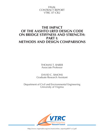
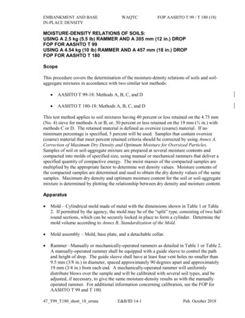
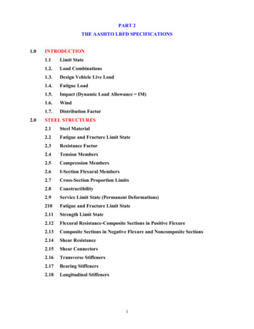
FIGURE 1-1 LRFD DESIGN VEHICULAR LIVE LOAD, HL-93-6
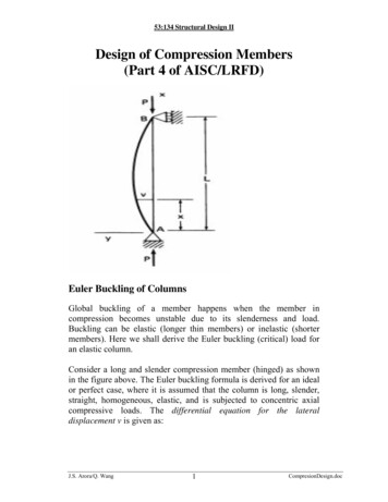
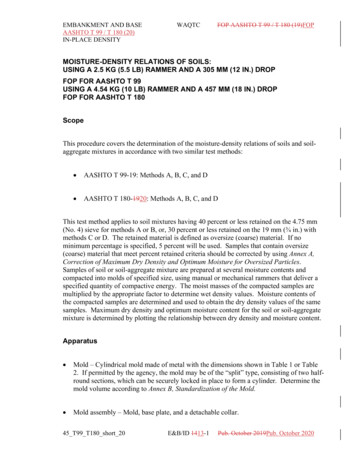
1.3.Design Vehicular Live Load(LRFD Art. 3.6.1.2)The vehicular live loading for LRFD is designated HL-93 (Figure 2-1), which consists ofa combination of the:(1)Design Truck Design Lane(2)Design Tandem Design Lane!For M - or Reactions at interior piers, two 90% Design Trucks spaced at least 50ft 90% Design LaneMultiple presence factors are not to be applied to the fatigue limit state for which onedesign truck is used, regardless of the number of design lanes. Thus, the factor 1.20 must beremoved from the single lane distribution factors when they are used to investigate fatigue.Number of LoadedMultiple PresenceLanesFactors, m11.2021.0030.85 30.65FIGURE 1-2 AASHTO LRFD MULTIPLE PRESENCE FACTORS-7
1.4.Fatigue LoadDesign truck only with constant 30' between 32-kip axles.(LRFD Art. 3.6.1.4)ADTTsingle-lane p x ADTTwhere p 1.0for one-lane bridge 0.85for two-lane bridge 0.80for three-lane or more bridgeClass of HighwayExample:(LRFD Eq. 3.6.1.4.2-1)ADTT/ADTRural Interstate0.2Urban Interstate0.15Other Rural0.15Other Urban0.10Rural Interstate 4-lane bridge (Major)ADTTsingle-lane (0.8)(0.2)ADT 0.16 ADT 0.1275 ADTRural 2-lane bridge (Minor)1.5.ADTTsingle-lane (0.85)(0.15)ADT(Max ADT20,000 vehicles/lane/day) Impact (Dynamic Load Allowance IM)Deck Joints—All Limit States(LRFD Art. 3.6.2)IM 75%All other components, Fatigue and Fracture Limit StateIM 15%All other components, All other Limit StatesIM 33%Applied to design truck or tandem only; not to be applied to pedestrian loads or to thedesign lane load.-8
1.6.Wind(1)On structure: WS(a)(b)(LRFD Art. 3.8)WindwardLeewardTrusses, Columns0.05 ksf0.025 ksfand Arches(0.30 klf min.)(0.15 klf min.)Beams0.05 ksf*HVD2 / 10,000NA(0.30 klf min.)(c)Large Flat Surfaces0.04 ksfNAA multi-girder bridge. 55 mph design Wind. d 5 p 0.05 x 5 x 552 / 10,000 0.075625 klf 0.30 x 552 / 10,000 0.09075 klf(2)On Vehicles 1.7.Distribution FactorWL govern(100 lb/ft acting 6 ft above the roadway, based on 55 mph)(LRFD Art. 4.6.2.1 & 2)(Decks & Steel I-Beams, Prestress Concrete, Concrete T-Beam on Concrete deck)1.7.1Distribution Factor for Deck(LRFD Art. 4.6.2.1)The width of the equivalent strip of a deck may be taken as specified in AASHTO LRFDTable 4.6.2.1.3-1For Concrete Deck (in.): Cast-in-Place:o Overhang:45.0 10.0Xo Parallel/Perpendicular; M26.0 6.6S- M48.0 3.0S(also for Cast-in-Place w/Stay-in-Place concrete formwork and Precast/Post-tensioned)Where S spacing of supporting components (ft) and X distance from load to point of support.1.7.2 Distribution Factor for Beam-Slab BridgesDefinition:(LRFD Art. 4.6.2.2)The AASHTO Specs permit a simplified method by modeling a longitudinalgirder or a strip of unit width for obtaining longitudinal moments and shears dueto live load. This beam is isolated from the rest of the structure and treated as aone-dimensional beam. This isolated beam is subjected to loads comprising oneaxle of the design vehicle multiplied by a load fraction “g.” This “g” is defined as-9
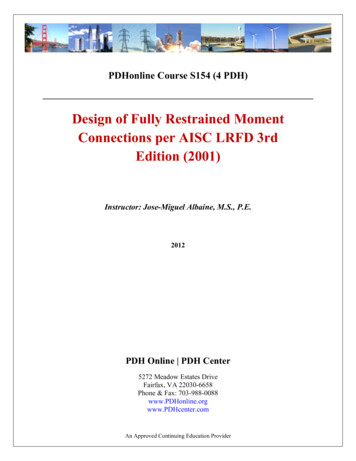
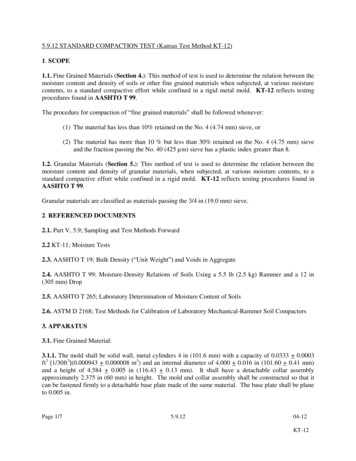
Axle Load Distribution Factor in LRFD Specs., which is different from the WheelLoad Distribution Factor defined in the AASHTO Specs.A.Moment (1)Interior —(a)One laneg interior(b)(Table 1-3 & AASHTO LRFD Table 4.6.2.2.2b-1)0.40.3 S S k g 0.06 3 14 L 12 Lt s 0.1Two or more lanesg interior0.60.2 S S k g 0.075 3 9.5 L 12 Lt s 0.13 6 S 16 , 4.5 t s 12 , 20 L 240 , N b 4(c)(2)Use lesser of (a) and (b) with Nb 3 or the lever ruleExterior —(Table 1-4 & AASHTO LRFD Table 4.6.2.2.2d-1)(a)One laneUse level rule.(b)Two or more lanes,gexterior e ginteriore 0.77 de / 9.1(c)NL X ext e Nb R N L Nb 2 x –1′ – 0″ de 5′ – 6″NL no of lanesNb no of girdersXext distance from CG of girder to ext. girdere eccentricity of lanes from CG of girders0 .1FIGURE 1-3 ILLUSTRATION OF THE G-VALUE METHOD-10
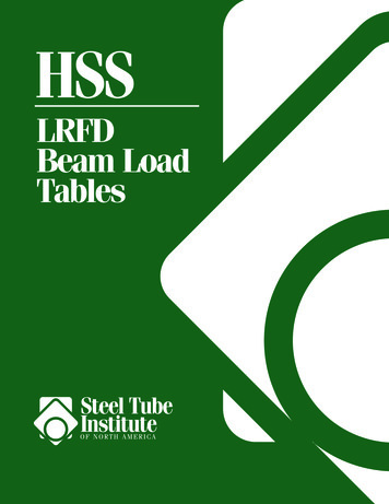
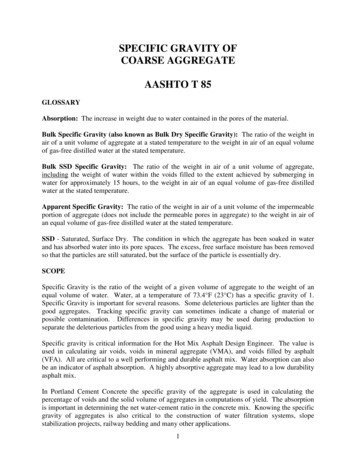
TABLE 1-3 AASHTO TABLE FOR THE MOMENT DISTRIBUTION FACTOR OF THEINTERIOR BEAMS(AASHTO LRFD Table 4.6.2.2.2b-1 – Distribution of Live loads Per Lane for Moment in interior Beams)Type of BeamsWood Deck onWood or SteelBeamsConcrete Deck onWood BeamsConcrete Deck,Filled Grid,Partially FilledGrid or UnfilledGrid DeckComposite withReinforcedConcrete Slab onSteel or ConcreteBeams; ConcreteT-Beams, T- andDouble T-SectionsCast-in-PlaceConcrete MulticellBoxConcrete Deck onConcrete SpreadBox BeamsApplicableCross-Sectionfrom Table –4.6.2.2.1-1a, lDistribution FactorslOne Design Land Loaded: S/12.0Two or More Design Lanes Loaded: S/10.0One Design Lane Loaded:a, e, k andalsoi, jif sufficientlyconnected toact as a unitRange ofApplicabilitySee Table 4.6.2.2.2a-10.40.10.3 S S K g 0.06 3 14 L 12.0 Lt s Two or More Design Lanes Loaded:0.10.60.2 S S K g 0.075 3 9.5 L 12.0 Lt s S 6.03.5 S 16.04.5 ts 12.020 L 240Nb 410,000 Kg 7,000,000Nb 3Use lesser of the values obtained from theequation above with Nb 3 or the lever rule.dOne Design Lane Loaded:0.350.45S 1 1 1.75 3.6 L N c Two or More Design Lanes Loaded:b, c0.30.250.350.250.60.125 13 S 1 N c 5.8 L One Design Lane Loaded: S Sd 2 3.0 12.0 L Two ore More Design Lanes Loaded: S Sd 2 6.3 12.0 L Use Lever Rule-117.0 S 13.060 L 240Nc 3If Nc 8 useNc 86.0 S 18.020 L 14018 d 65Nb 3S 18.0
TABLE 1-3 AASHTO TABLE FOR THE MOMENT DISTRIBUTION FACTOR OF THEINTERIOR BEAMS(Continued)Type of BeamsConcrete BeamsUsed in MultiBeam DecksApplicableCross-Sectionfrom Table –4.6.2.2.1-1fDistribution FactorsOne Design Lane Loaded:0.5g b I k 33.3L J where: k 2.5 (Nb)-0.2 1.5Two or More Design Lanes Loaded:0.6hi, jif connectedonly enough toprevent relativeverticaldisplacement atthe interfaceOpen Steel GirdDeck on SteelBeamsConcrete deckon Multiple SteelBox Girdersab, c0.250.235 b 6020 L 1205 Nb 200.06 b b I k 305 12.0 L J Regardless of Number of Loaded Lanes:S/Dwhere:C K (W/L)D 11.5 – NL 1.4 NL (1 – 0.2C )2when C 5D 11.5 – NL when C 5 1 IK Jfor preliminary design, the following valueof K may be used:Beam TypeKNonvoided rectangular beams0.7Rectangular beams withcircular voids:0.8Box section beams1.0Channel beams2.2T-Beam2.0Double T-Beam2.0One Design Lane Loaded:S/7.5 if tg 4.0 INS/10.0 if tg 4.0 INTwo or More Design Lanes Loaded:S/8.0 if tg 4.0 INS/10.0 if tg 4.0 INRegardless of Number of Loaded Lanes:N0.4250.05 0.85 L NbNL2-12Range ofApplicabilitySkew 45 NL 6S 6.0 FTS 10.5 FT0.5 NL 1.5Nb
TABLE 1-4 AASHTO TABLE FOR THE MOMENT DISTRIBUTION FACTOR OF THEEXTERIOR BEAMS (AASHTO LRFD Table 4
(Decks & Steel I-Beams, Prestress Concrete, Concrete T-Beam on Concrete deck) 1.7.1 Distribution Factor for Deck (LRFD Art. 4.6.2.1) The width of the equivalent strip of a deck may be taken as specified in AASHTO LRFD Table 4.6.2.1.3-1 For Concrete Deck (in.): Cast-in-Place: o Overhang: 45.0 10.0X