Transcription
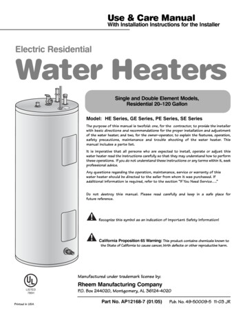
Use & Care ManualWith Installation Instructions for the InstallerElectric ResidentialWater HeatersSingle and Double Element Models,Residential 20–120 GallonModel: HE Series, GE Series, PE Series, SE SeriesThe purpose of this manual is twofold: one, for the contractor, to provide the installerwith basic directions and recommendations for the proper installation and adjustmentof the water heater; and two, for the owner–operator, to explain the features, operation,safety precautions, maintenance and trouble shooting of the water heater. Thismanual includes a parts list.It is imperative that all persons who are expected to install, operate or adjust thiswater heater read the instructions carefully so that they may understand how to performthese operations. If you do not understand these instructions or any terms within it, seekprofessional advice.Any questions regarding the operation, maintenance, service or warranty of thiswater heater should be directed to the seller from whom it was purchased. Ifadditional information is required, refer to the section “If You Need Service .”Do not destroy this manual. Please read carefully and keep in a safe place forfuture reference.!!Recognize this symbol as an indication of Important Safety Information!California Proposition 65 Warning: This product contains chemicals known tothe State of California to cause cancer, birth defects or other reproductive harm.Manufactured under trademark license by: LISTED786HPrinted in USARheem Manufacturing CompanyP.O. Box 244020, Montgomery, AL 36124-4020Part No. AP12168-7 (01/05)Pub. No. 49-50009-5 11-03 JR
Safety InstructionsSafety InformationIMPORTANT!Safety Precautions . . . . . . 3, 4Fill out and return the Consumer Product Registration Card that isin the back of this manual.FOR YOUR RECORDSCustomer ServiceTroubleshooting TipsCare and CleaningOperating InstructionsInstallation InstructionsWrite the model and serial numbers here:Installation Instructions#Location . . . . . . . . . . . . . . . . . . 5#Water Connections . . . . . . . . 6You can find them on a label on the appliance.Electrical Connections . . . . . 8Staple sales slip or cancelled check here.Proof of the original purchase date is needed to obtain serviceunder the warranty.Operating InstructionsSafety Controls . . . . . . . . . . . 12Water Temperature . . . . . . . . 13READ THIS MANUALInside you will find many helpful hints on how to use and maintainyour water heater properly. Just a little preventive care on yourpart can save you a great deal of time and money over the life ofyour water heater.You’ll find many answers to common problems in the Before YouCall For Service section. If you review our chart of TroubleshootingTips first, you may not need to call for service at all.Care and CleaningIF YOU NEED SERVICEDraining . . . . . . . . . . . . . . . . . . 14If you do need service, you can relax knowing help is only a phonecall away. For service call 800-431-1549.Extended Shut-Down . . . . . . 14Maintenance. . . . . . . . . . . . . . 14READ THE SAFETY INFORMATIONYour safety and the safety of others are very important. Thereare many important safety messages in this manual and on yourappliance. Always read and obey all safety messages.Troubleshooting Tips!Before You CallFor Service. . . . . . . . . . . . . . . . 15This is the safety alert symbol. Recognize this symbolas an indication of Important Safety Information! Thissymbol alerts you to potential hazards that can kill orhurt you and others.All safety messages will follow the safety alert symbol and eitherthe word “DANGER”, “WARNING”, “CAUTION” or “NOTICE”.These words mean:!DANGERAn imminently hazardous situation that willresult in death or serious injury.!WARNINGA potentially hazardous situation that couldresult in death or serious injury and/ordamage to property.!CAUTIONA potentially hazardous situation that mayresult in minor or moderate injury.Customer ServiceParts List . . . . . . . . . . . . . . . . 16Wiring Diagram . . . . . . . . . . . 18Product Registration . . . . . . 192Notice:Attention is called to observe a specifiedprocedure or maintain a specific condition.
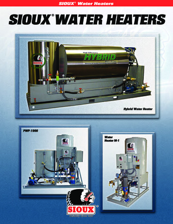
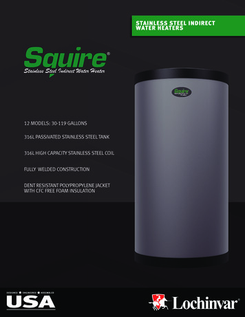
Safety InstructionsIMPORTANT SAFETY INFORMATION.READ ALL INSTRUCTIONS BEFORE USING.WARNING!WATER TEMPERATURE ADJUSTMENTInstallation InstructionsSafety and energy conservation are factors to be considered when selecting the watertemperature setting of water heater’s thermostat. Water temperatures above 125 F cancause severe burns or death from scalding. Be sure to read and follow the warnings outlinedon the label pictured below. This label is also located on the water heater near thethermostat access panel.Time/Temperature Relationship in Scalds!DANGERTime To Produce a Serious Burn120 F125 F130 F135 F140 F145 F150 F155 FMore than 5 minutes11/2 to 2 minutesAbout 30 secondsAbout 10 secondsLess than 5 secondsLess than 3 secondsAbout 11/2 secondsAbout 1 secondOperating InstructionsTemperatureTable courtesy of Shriners Burn InstituteESEThermostatdial pointer150 F(66 C)90 F(32 C)125 F (52 C)TURN OFFPOWERBEFORESERVICINGRefer to the OperatingInstructions in thismanual for detailedinstructions in how toadjust the thermostat(s).DANGER: Hotter water increase the potential forHot Water SCALDS.3Customer ServiceThermostatprotectivecoverThe illustration at the leftshows the temperatureadjustment dial usedfor setting the watertemperature.Troubleshooting TipsTESENOTICE: Mixing valves are available for reducing point ofuse water temperature by mixing hot and cold water inbranch water lines. Contact a licensed plumber or thelocal plumbing authority for further information.Reset buttonRChildren, disabled and elderly areat highest risk of being scalded.See instruction manual beforesetting temperature at waterheater.Feel water before bathing orshowering.Temperature limiting valves areavailable, see manual.The temperature of the water in the heater isregulated by the adjustable surface mountedthermostat(s) located behind the jacket accesspanel(s). Dual element heaters have twothermostats. To comply with safety regulationsthe thermostat(s) were set at 120 F before thewater heater was shipped from the factory.RWater temperature over 125 F cancause severe burns instantly ordeath from scalds.NOTICE: Households with small children, disabled,or elderly persons may require a 120 F or lowerthermostat setting to prevent contact with “HOT”water.Care and CleaningBURNThe chart shown above may be used as a guidein determining the proper water temperature foryour home.THOT
WARNING!For your safety, the information in this manual must be followed to minimize the risk of fireor explosion, electric shock, or to prevent property damage, personal injury, or loss of life.Be sure to read and understand the entire Use and Care Manual before attempting toinstall or operate this water heater. It may save you time and cost. Pay particular attentionto the Safety Instructions. Failure to follow these warnings could result in serious bodilyinjury or death. Should you have problems understanding the instructions in this manual,or have any questions, STOP, and get help from a qualified service technician, or the localelectric utility.Installation InstructionsSafety InstructionsIMPORTANT SAFETY INFORMATION.READ ALL INSTRUCTIONS BEFORE USING.Operating InstructionsFOR INSTALLATIONS IN THE STATE OF CALIFORNIACalifornia Law requires that residential water heaters must be braced, anchored orstrapped to resist falling or horizontal displacement due to earthquake motions. Forresidential water heaters up to 52 gallon capacity, a brochure with generic earthquakebracing instructions can be obtained from: Office of the State Architect, 400 P Street,Sacramento, CA 95814 or you may call 916-324-5315 or ask a water heater dealer.Care and CleaningHowever, applicable local codes shall govern installation. For residential water heatersof a capacity greater than 52 gallons, consult the local building jurisdiction for acceptablebracing procedures.SAFETY PRECAUTIONSHave the installer show you the location of the circuit breaker and how to shut itoff if necessary. Turn off the circuit breaker if the water heater has beensubjected to overheating, fire, flood, physical damage or if the ECO fails to shutoff.Troubleshooting Tips Read this manual entirely beforeinstalling or operating the water heater. Use this appliance only for its intendedpurpose as described in this Use andCare Manual. Do not attempt to repair or replace anypart of your water heater unless it isspecifically recommended in this manual.All other servicing should be referred to aqualified technician. Be sure your appliance is properlyinstalled in accordance with local codesand the provided installationinstructions.Customer ServiceREAD AND FOLLOW THIS SAFETY INFORMATIONCAREFULLY.SAVE THESE INSTRUCTIONS4
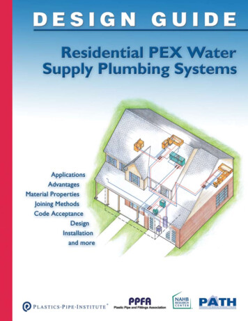
The location chosen for the water heater must take into consideration the following:Local Installation RegulationsElectrical Code. It is available from somelocal libraries or can be purchased fromthe National Fire Protection Association,Batterymarch park, Quincy, MA 02269as booklet ANSI/NFPA 70.LocationLocate the water heater in a clean dryarea as near as practical to the area ofgreatest heated water demand. Longuninsulated hot water lines can wasteenergy and water.Place the water heater in such a mannerthat the thermostat and elementaccess panels can be removed to permitinspection and servicing such as removalof elements or checking controls.The water heater and water lines shouldbe protected from freezingtemperatures. Do not install the waterheater in outdoor, unprotected areas.Care and CleaningBA—Diameter of waterheater plus 2″ min.B—Maximum 2″Operating InstructionsCAUTION: The water heater shouldnot be located in an area where leakageof the tank or connections will result indamage to the area adjacent to it or tolower floors of the structure. Wheresuch areas cannot be avoided, it isrecommended that a suitable catchpan, adequately drained, be installedunder the water heater.Installation InstructionsThis water heater must be installed inaccordance with these instructions, localcodes, utility codes, utility companyrequirements or, in the absence of localcodes, the latest edition of the NationalSafety InstructionsInstalling the water heater.ATroubleshooting TipsTo open drain, lineshould be at least 3/4″ID and pitched forproper drainage.NOTICE: Auxiliary catch pan MUST conform to local codes.Catch Pan Kits are available from the store where the waterheater was purchased, or any water heater distributor.Customer ServiceInspect ShipmentInspect the water heater for possible damage. Check the markings on the ratingplate of the water heater to be certain the power supply corresponds to the waterheater requirements.5
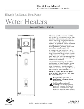
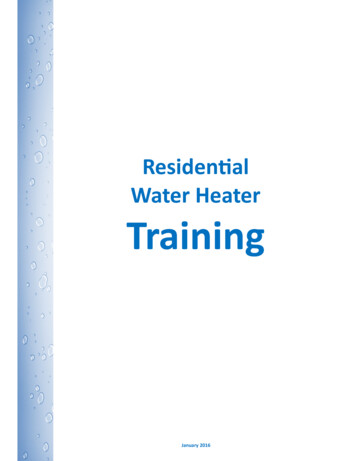
Thermal ExpansionDetermine if a check valve exists in the inlet water line. It may have been installedin the cold water line as a separate back flow preventer, or it may be part of a pressurereducing valve, water meter or water softener. A check valve located in the cold water inletline can cause what is referred to as a “closed water system”. A cold water inlet line withno check valve or back flow prevention device is referred to as an “open” water system.As water is heated, it expands in volume and creates an increase in the pressure withinthe water system. This action is referred to as “thermal expansion”. In an “open” watersystem, expanding water which exceeds the capacity of the water heater flows back intothe city main where the pressure is easily dissipated.A “closed water system”, however, prevents the expanding water from flowing back intothe main supply line, and the result of “thermal expansion” can create a rapid anddangerous pressure increase in the water heater and system piping. This rapid pressureincrease can quickly reach the safety setting of the relief valve, causing it to operate duringeach heating cycle. Thermal expansion, and the resulting rapid and repeated expansion andcontraction of components in the water heater and piping system can cause prematurefailure of the relief valve, and possibly the heater itself. Replacing the relief valve will notcorrect the problem!The suggested method of controlling thermal expansion is to install an expansion tank inthe cold water line between the water heater and the check valve (refer to the illustrationbelow). The expansion tank is designed with an air cushion built in that compresses as thesystem pressure increases, thereby relieving the over pressure condition and eliminating therepeated operation of the relief valve. Other methods of controlling thermal expansion arealso available. Contact your installing contractor, water supplier or plumbing inspector foradditional information regarding this subject.Water Supply ConnectionsNOTICE: Do not apply heatRefer to the illustration below for suggested typical installation. The installation ofto the HOT or COLD waterunions or flexible copper connectors is recommended on the hot and cold waterconnections. If sweatconnections so that the water heater may be easily disconnected for servicing ifconnections are used,necessary. The HOT and COLD water connections are clearly marked and are 3/4″ NPTsweat tubing to adapteron all models. Install a shut-off valve in the cold water line near the water heater.before fitting adapter to thewater connections onTypical Installationheater. Any heat applied toTo electricalUnionthe water supply fittingsTemperature anddistribution panelVacuum Relief Valvewill permanently damagepressure relief valve(Not Supplied)Heat trapthe dip tube and/or heat6″ minimumtraps.To cold watersupplyLDVAUnionCOLVFEILEERShut-off valveHeat trap6″ minimumCustomer ServiceHot water outletto fixturesThermalexpansion tank(if required)TIf required, install per local codesand valve manufacturer’sinstructions.HOTroubleshooting TipsCare and CleaningOperating InstructionsInstallation InstructionsSafety InstructionsInstalling the water heater.AnodeElectrical junction box(use only copper conductors)Jacket access panelJacket access panelRelief valve discharge lineto suitable open drain6Auxiliary catch pan2″ maximum6″ air gapDrain valve
Safety InstructionsA new combination temperature and pressure relief valve, complying with the Standard for Relief Valvesand Automatic Gas Shut-Off Devices for Hot Water Supply Systems, ANSI Z21.22, is supplied and mustremain installed in the opening provided and marked for the purpose on the water heater. No valve of anytype should be installed between the relief valve and the tank. Local codes shall govern the installation ofrelief valves.Relief ValveThe BTUH rating of the relief valve mustnot be less than the input rating of thewater heater as indicated on the ratinglabel located on the front of the heater(1 watt 3.412 BTUH).To Fill the Water HeaterMake certain the drain valve is completelyclosed.Open the shut-off valve in the cold watersupply line.Open each hot water faucet slowly toallow the air to vent from the waterheater and piping.A steady flow of water from the hot waterfaucet(s) indicates a full water heater.Condensation can form on the tankwhen it is first filled with water.Condensation might also occur with aheavy water draw and very cold inletwater temperature.Troubleshooting TipsCondensationCare and CleaningWARNING: The tank must be full ofwater before heater is turned on. Thewater heater warranty does not coverdamage or failure resulting fromoperation with an empty or partiallyempty tank. (Refer to the Certificate ofLimited Warranty for complete termsand conditions.)Operating InstructionsConnect the outlet of the relief valveto a suitable open drain so that thedischarge water cannot contact liveelectrical parts or persons and toeliminate potential water damage.Piping used should be of a type approvedfor hot water distribution. The dischargeline must be no smaller than the outletof the valve and must pitch downwardfrom the valve to allow completedrainage (by gravity) of the relief valveand discharge line. The end of thedischarge line should not be threaded orconcealed and should be protected fromfreezing. No valve of any type, restrictionor reducer coupling should be installed inthe discharge line.Installation InstructionsWARNING: The pressurerating of the relief valvemust not exceed 150 PSI,the maximum workingpressure of the waterheater as marked onthe rating plate.Additional information on this subjectmay be found at www.rheem.comunder “Library”. Scroll down to theTechnical Service Bulletins 1300 SeriesSection and choose Bulletin #1303.Customer ServiceThis condition is not unusual, and willdisappear after the water becomesheated. If, however, the condensationcontinues, examine the piping andfittings for possible leaks.7
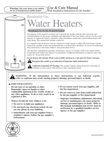
Safety InstructionsInstallation InstructionsGround screwNINGWARConduitconnectorJunctionboxcoverWire connectionsWater heater junction box.CAUTION: The presenceof water in the piping andwater heater does notprovide sufficientconduction for a ground.Non-metallic piping,dielectric unions, flexibleconnectors etc. can causethe water heater to beelectrically isolated.Electrical ConnectionsA separate branch circuit with copperconductors, overcurrent protective deviceand suitable disconnecting means mustbe provided by a qualified electrician.All wiring must conform to local codesor latest edition of National ElectricalCode ANSI/NFPA 70.The water heater is completely wired tothe junction box inside jacket at the topfront of the water heater. An opening for1/2″ or 3/4″ electrical fitting is providedfor field wiring connections.The voltage requirements and wattageload for the water heater are specifiedon the rating plate on the front of thewater heater.The branch circuit wiring shouldinclude either:Metallic conduit or metallicsheathed cable approved for use asa grounding conductor andinstalled with fittings approved forthe purpose.Non-metallic sheathed cable,metallic conduit or metallicsheathed cable not approved foruse as a ground conductor shallinclude a separate conductor forgrounding. It should be attached tothe ground terminals of the waterheater and the electricaldistribution box.NOTICE: This guide recommends minimum branch circuit sizing and wire size based on National Electric Code.Refer to wiring diagrams in this manual for field wiring connections.Branch Circuit Sizing and Wire Size GuideCare and CleaningOperating InstructionsInstalling the water heater.Total WaterHeater WattageCustomer ServiceTroubleshooting 11,00012,0008Recommended Over Current Protection(fuse or circuit breaker amperage 5151515202525303035Copper Wire Size AWG Basedon N.E.C. Table 310-16 (75 108
Safety InstructionsInsulation BlanketsInsulation blankets, available to thegeneral public, for external use onelectric water heaters are not necessary.The purpose of an insulation blanket isto reduce the standby heat lossencountered with storage tank heaters.This water heater meets or exceeds theNational Appliance Energy ConservationAct standards with respect toinsulation and standby lossrequirements making an insulationblanket unnecessary. Do not cover the operating or warninglabels attached to the water heater orattempt to relocate them on theexterior of insulation blanket. Do not apply insulation to the top ofthe water heater. this could interferewith the safe operation of theelectrical junction box. Do not cover the jacket accesspanel(s) to the thermostat(s) andheating element(s), or pressure andtemperature relief valve.Operating InstructionsThe manufacturer’s warranty does notcover any damage or defect caused byinstallation, attachment or use ofany type of energy saving or otherunapproved devices (other than thoseauthorized by the manufacturer) into,onto or in conjunction with the wa
Rheem Manufacturing Company P.O. Box 244020, Montgomery, AL 36124-4020 Printed in USA Use & Care Manual With Installation Instructions for the Installer. Safety Information . Installation Instructions Operating Instructions Care and Cleaning Troubleshooting Tips Customer ServiceFile Size: 407KB