Transcription
ASHRAE 62.1 VentilationCompliance EvaluationRendering Courtesy Moody·Nolan, Inc.George W. Hays PK-8Cincinnati Public SchoolCincinnati, OHPrepared ForDr. Jelena SrebricByRodrick A. CrouseyThe Pennsylvania State UniversityArchitectural EngineeringMechanical OptionOctober 6, 2006
Table of ContentsExecutive Summary.1Assumptions . . . .2Procedures . . 6Sample Calculations . 10System and Building Summary. . . .12AHU-1. 13AHU-2 . .14AHU-3 .15Discussion . .17Appendix A: AHU-1 . 19Appendix B: AHU-2 . 28Appendix C: AHU-3 . 38Bibliography . .39
Executive SummaryThis report investigates the adequacy of outdoor air for the George W. HaysPublic School in Cincinnati. To do this the designed values of outdoor air(OA) were compared against values determined using ASHRAE Standard62.1-2004 ventilation requirements at design conditions. The Ventilation RateCalculation Procedure was used and is found in Section 6 of Standard 62.1.This procedure is based on floor area, number of occupants, space category,and the air distribution system.The structure contains three Air Handling Units (AHU’s) that are responsiblefor supplying OA to every space in the building. AHU-1 serves the three storyclassroom wing of the building. AHU-2 serves 1st and 2nd floor classrooms.AHU-3 serves the gymnasium and the gymnasium support areas.It was found that AHU-1 and AHU-2 do not meet the OA requirements ofASHRAE 62.1, while AHU-3 did meet the required minimum OA. AHU-1 issignificantly under ventilated while AHU-2 is near ventilation requirements.Both of these discrepancies can be traced to different assumptions about therequired OA design conditions and about OA requirements to particularzones. AHU-3 meet the requirements because of one dominating space forwhich design assumptions and calculated assumptions were similar.The OA to the building was based on OA requirements of the Ohio MechanicalCode that only have a per person or per sq ft OA requirement. ASHRAE Std.62.1-2004 has a required OA per person and per sq ft for each space. Thisrequirement is to account for potential pollutants that may be produced fromcomponents of the room other then people. Because of the discrepanciesbetween the OBC and ASHRAE 62.1 OA requirements for 62.1 were not meetfor the George W. Hays Public School.-1-
Assumptions No smoking – There will be no smoking in any areas of the building ornear OA intake locations.Acceptable OA – The Regional and Local Air OA Quality is acceptable forsupply and complies with ASHRAE 62.1 Section 4.No Noxious or Dangerous Return Air – Any noxious or dangerous air thatmay be generated in the building will be exhausted directly with asufficient fume hood and will not enter the return air.Az .9 Agross – For each zone, the “Breathing Zone” Area, Az, was estimatedto be 90% of the net floor area in each space. This assumption is to allowfor a two foot parameter around the room that is, by definition, notconsidered part of the Breathing Zone. This assumption was tested withthe largest zone because the 90% assumption would be most likely to beproven wrong in a large rectangular space. The largest zone was theGymnasium, with room dimensions of 84’x71’, giving a total area of 5960ft2. This was put in contrast with a space having walls 80’x67’ to fit thedefined Occupied Zone. This area was found to be 5360 ft2, 89.9% of theroom area. Thus it was concluded that the 90% assumption was safe in allsmaller spaces.Ez 1 – Zone distribution effectiveness, Ez accounts for the ability of thezone to properly mix the supply air with the room air. Ez for each zone wasgiven a value of 1.0 in accordance with Table 6.2 Std. 62.1. All zones havea ceiling supply of cold air, where OA values were found using coolingairflow rates.D1 can be solved for – Diversity values for AHU-1 (serving the mainclassroom wing of the building) could be found by subtracting outpopulations of zones with local conference and meeting uses from the sumof the population of each individual zone. This value was made the PeakSystem Population. It was assumed that the local conference areas wouldonly hold populations coming from different zones exclusively from AHU1. This assumption is further backed up by the Peak System Population inAHU-1 having a lower value then the total design student population for theentire building. The zones that qualified as “local conference and meetingrooms,” were:Teachers Preps; Rooms 111, 209, & 303Extended Learning Areas; Rooms 113, 120, 211, 218, 305Workroom / Conference; 304D2 & D3 are 1.0 – The diversity for AHU-2 & AHU-3 was assumed to be 1.0.Conference and meeting zones in AHU-2 and AHU-3 were not subtracted to-2-
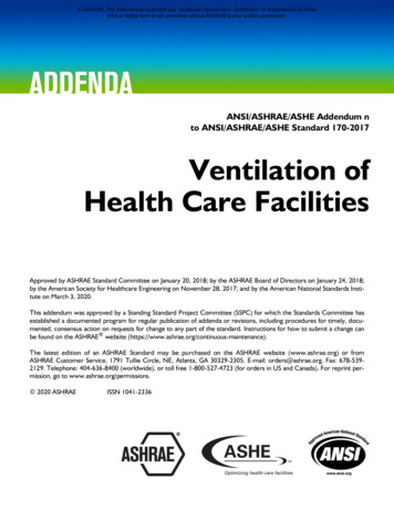
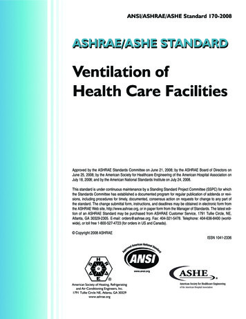
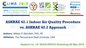
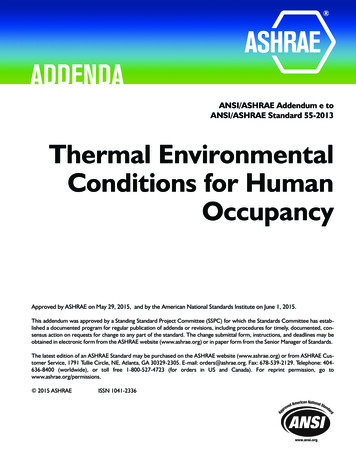
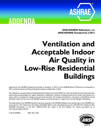
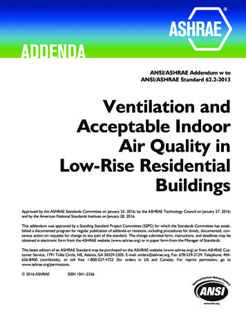
find a diversity value because those populations were assumed to becoming from outside the building or from other AHU’s.Vdzmin .6 Vdzmax – It was assumed that the minimum expected value ofsupply to each terminal device during full occupation was equal to 60% ofthe maximum expected airflow. The minimum setting of 40% on each VAVwas not used since this setting is not expected with full occupancy,because the building has a small envelope load and many loadsdependant on occupancy, such as lighting and computers. This is furtherproven because in many of the spaces, such as Rm 113, the minimum VAVsetting, 360 cfm is less then the designed OA of 390. This implies that theminimum setting of the VAV was not intended for use during occupancyhours.OAbathrooms 0 – It was assumed that all restrooms were exhaust only anddid not require an OA supply.OAclosets 0 – It was assumed that all small janitor’s closets too small tohave an occupancy did not require an OA supply.ASHRAE Std. 62.1 was interpreted in such a way that default values forpersons in a zone were left as fractions when the equation did not equal around number.In rooms where the design occupancy was lower then seemed reasonable,the ASHRAE 62.1 default value was used. For example, conference room304, 157 sq. ft. was designed for 1 person. This value was discarded forbeing unreasonable and the ASHRAE default value of 6.85 was used.The following tables list assumptions for OA flow rate values, spacepopulations, and Space types used in accordance with 62.1 Table 6.1. Thecriteria for the selection of OA flow rate values and space populations isalso shown. ASHRAE refers to values found in Table 6.1 in ASHRAE Std.62.1. All space square footages are shown in the respective Appendix.AHU-3-3-
AHU-1-4-
AHU-2-5-
ProceduresThe building was broken up into three main zones. Each of the three airhandling units were made responsible for supplying an appropriateamount of Outdoor Air (OA) to each zone. To determine the minimumOA, Section 6 of ASHRAE Standard 62.1-2004 was used. The calculationsfor determining the minimum amount of required outdoor air weresimilar for each of the three zones and went in acquaintance with thefollowing steps.STEP 1: ADDITIVITYEquations Used:Vbz Rp*Pz Ra*Az (Equation 6-1)Definitions:Vbz CFM required for the breathing Zone.Rp CFM required per person for the Zone.Ra CFM required per square foot of the Zone.Pz Number of people expected in the zone.Az Area of the breathing zoneBreathing Zone- The region within an occupied space between planes3 and 72 inches above the floor and more than 2 ft from the walls orfixed air-conditioning equipment. (Section 3, Std. 62.1)Discussion:All values for Az were determined to be 90% of the total room area(See assumptions).All values for Rp and Ra were determined using Table 6.1 of Std. 62.1.In determining Pz, spaces where the known occupancy appeared ondocuments, Pz was set to the known occupancy. In cases with norecord of known occupancy or with values of occupancies seemingquestionably low values for Pz were determined using Table 6.1 ofStd. 62.1 (See assumptions).-6-
STEP 2: ZONE OUTDOOR AIRFLOWEquations Used:Voz Vbz/Ez (Equation 6-2)Definitions:Ez Ratio of the airflow entering the breathing zone to the airflowdelivered to the diffusers.Voz OA that must reach the zone in order to supply a proper amountof OA to the breathing zone, considering distribution effectiveness.Discussion:Ez values were all assumed to be 1.0 by using Table 6.2 of Std. 62.1.(See assumptions).STEP 3: DISCHARGE OA FRACTIONEquations Used:Zd Voz / Vpzmin (By Definition, Appendix A)Definitions:Zd Fraction of OA in the primary airflow to a zone (also referred toas Zd).Vpzmin Minimum expected primary supply airflow to a zone.Discussion:Vpzmin values were found from analyzing system, drawings, andschedules (See assumptions).STEP 4: UNCORRECTED OA INTAKEEquations Used:D Peak System Population / Peak Zone Populations (Equation 6-7)Vou D* (Rp*Pz) (Ra*Az) (Equation 6-6)-7-
Definitions:D Population diversity for the zones served by the AHU.Vou Uncorrected OA intake flow for all zones, not adjusted forventilation efficiency, Ev.Discussion:Diversity values for AHU-2 & AHU-3 were estimated to be 1.0 (Seeassumptions). The diversity for AHU-1 was determined bysubtracting out the populations of zones that were expected to onlycontain occupants from other zones still served by AHU-1 from thesum of each individual zone. This value was assumed to be the peaksystem population (See assumptions).STEP 5: CRITICAL ZONE VENTILATION EFFICIENCY (APPENDIX A)Equations Used:Xs Vou / Vps (By Definition, Appendix A)Vps Vpz (By Definition, Appendix A)Fa Ep (1-Ep)*Er (By Definition, Appendix A)Ep Vpz/Vdz (By Definition, Appendix A)Fb Ep (By Definition, Appendix A)Fc 1-(1-Ez) (By Definition, Appendix A. Note: there are othercomponents to this equation however; they are all multiplied by(1-Ez). Because of the assumption that Ez in every space is equalto 1.0, these other terms are multiplied by zero.Evz (Fa Xs * Fb – Zd * Fc) / Fa (Equation A-2)Ev min[Evz] (By Definition, Appendix A)-8-
Definitions:Xs Uncorrected average outdoor-air intake fraction.Vps Total system primary airflowEvz Zone ventilation efficiencyEv Critical zone ventilation efficiencyDiscussion:Equation A-2 was used, regardless of Ev or the system setup. Becauseit was known that Ev would not be within the range of Table 6-3, andthat Table 6-3 makes the assumption of Zp being an average of .15 forreasons of uniformity and accuracy Appendix A was used for eachsystem. Since, A-2 covers scenarios in A-2 and A-1, for uniformityequation A-2 was used for each system.STEP: TOTAL OA INTAKE FLOWEquations Used:Vot Vou / Ev (Equation 6-8)Definitions:Vot Total intake OA flow adjusted for ventilation efficiency.Discussion:Vot for each AHU is the total value of OA required for the system. Thisvalue was then compared with the design values of OA to determine ifthe minimum OA values were met.-9-
Sample CalculationsSTEP 1: ADDITIVITYVbz Rp*Pz Ra*Az (Equation 6-1)Vbz 260 119.556 379.556STEP 2: ZONE OUTDOOR AIRFLOWVoz Vbz/Ez (Equation 6-2)Voz 379.556/1.0 379.556STEP 3: DISCHARGE OA FRACTIONZd Voz/Vpzmin (From Appendix A, ASHRAE 62.1)Zd 379.556/50 7.59112STEP 4: UNCORRECTED OA INTAKED Peak System Population / Peak Zone Populations (Equation 6-7)The only System for which a diversity value was calculated was forAHU-1 (See assumptions). Peak Zone Populations 727Peak System Population 727- Populations of local conference zones 727 – (14.2 26 26 15.8 26 26 14.05 6.85 26) 727 – 181 546D 546/727 0.75Vou D* (Rp*Pz) (Ra*Az) (Equation 6-6)- 10 -
Vou 0.75* 7014.5 2731.266 8000STEP 5: CRITICAL ZONE VENTILATION EFFICIENCY (APPENDIX A)(See assumptions)Vps Vpz (By definition, Std. 62n Appendix A)Vps 27190Xs Vou / Vps (By definition, Std. 62n Appendix A)Xs 8000 / 27190 0.294226Ep Vpz/VdzEp 900/900 1.0Fa Ep (1-Ep)*ErFa 1.0 0 1.0Fb EpFb 1.0Fc 1-(1-Ez)Fc 1-(1-1) 1.0Evz (Fa Xs * Fb – Zd * Fc) / FaEvz (1.0 0.294226 * 1.0 – 0.7 * 1.0) / 1.0 0.594226Ev min[Evz]Ev 0.59STEP 6: TOTAL OA INTAKE FLOWVot Vou / EvVot 8000/ 0.59 13546- 11 -
System and Building SummaryTotal Building Summary and FindingsThe building is broken up into three main zones. Each of the three airhandling units is responsible for supplying an appropriate amount of OutdoorAir (OA) to its respective zone. Each zone is mainly limited to a particulartype of space. This helps keep the critical space representative of the space,because the minimum Evz from Appendix A can be expected to be somewhatsimilar for spaces serving a similar function with similar OA requirements.Thus, limiting the amount of OA brought to unnecessary spaces. Each zone isserved by one AHU. Each AHU is an indoor modular Air Handling Unit locatedin a mechanical room or mezzanine. Each AHU has an integral heat recoverywheel, a return or relief fan, an economizer section, heating and cooling coiland a supply fan. The zone breakups according to AHU are shown in Table 51.TABLE 5-1Air Handling Unit Zone DistributionTable 5-2 further describes these zones by room types and total area. Theseare the Net areas, or “Breathing Zone” areas used for calculations (Seeassumptions). Table 5-2 also highlights the basic comparisons between the- 12 -
designed OA flow and the ASHRAE 62.1 calculated OA flow which will belooked at more ineptly in the subsequent sections. Specific data for each AHUis laid out in Appendices A-CTABLE 5-2Air Handling Unit SummaryThe sum of the Voz values in all zones served by AHU-1, AHU-2, and AHU-3was 18,890, or 65% of the some of the Vot values of 29,142 cfm. The reason forthis increase is the critical zone requiring a higher fraction of OA then some ofthe other zones. In order to supply a sufficient amount of OA to the criticalspace, the system is forced to supply excess OA to non-cr
ASHRAE 62.1, while AHU-3 did meet the required minimum OA. AHU-1 is significantly under ventilated while AHU-2 is near ventilation requirements. Both of these discrepancies can be traced to different assumptions about the required OA design conditions and about OA requirements to particular zones. AHU-3 meet the requirements because of one dominating space for which design assumptions File Size: 579KBPage Count: 41People also search forashrae 62 1 ventilation requirementsashrae ventilation 62 1