Transcription
PowerGlide ChassisAllegro BreezeOwner’s ManualTiffin Motorhomes, Inc.105 2nd Street NWRed Bay, AL 35582 U.S.A.Phone: (256) 356-8661E-Mail: info@tiffinmotorhomes.com[20110701]
A L L E G R OB R E E Z EP O W E R G L I D EC H A S S I SM A N U A L1VolumeTIFFIN MOTORHOMES, INC.105 2nd Street NW Red Bay, Alabama 35582 U.S.A. PowerGlideOwner’s Manual
A L L E G R OB R E E Z EP O W E R G L I D EC H A S S I SM A N U A LTIFFIN MOTORHOMES, INC.Allegro Breeze Chassis Owner’s Manual Tiffin Motorhomes, Inc.105 2nd Street NW, Red Bay, AL 35582 U.S.A.Telephone 256.356.8661 Facsimile 256.356.8219E-Mail: info@tiffinmotorhomes.comDISCLAIMERMany of the features and appliances described in this manual may or may not be reflected in theactual motor home purchased, depending on the options and models selected by the motorhomeowner. All items, materials, instructions, and guidance described in this manual are as accurateas possible at the time of printing. However, because of Tiffin Motorhomes’ ongoing anddedicated commitment to excellence, improvement of Tiffin motorhomes is a continuing process.Consequently, Tiffin Motorhomes reserves the right to make substitutions and improvements inits makes and models of motorhomes without prior notification. Substitutions of comparable orbetter materials, finishes, appliances, instrumentation, and instruction may be made at any timeit is deemed prudent to provide the customer with the best possible motorhome meeting thecustomer’s requirements.Copyright 2011 by Tiffin Motorhomes, Inc. -- all rights reservedPrinted in the United States of America: Fifth U.S. Printing: July 2011[20110710]
Allegro Breeze Tiffin PowerGlide ChassisCustomer Support256-356-0261Monday-Friday7 a.m. - 4:30 p.m. CSTIf you should require chassis service, you should first contact your nearest TiffinPowerglide Chassis service center. If for some reason this is not possible or if youwould like to call the manufacturers direct, you can contact them at the followingtelephone numbers:TIFFIN POWERGLIDE CHASSIS256-356-0261(Please have your VIN# ready)COACH-NET(Nights and weekends)1-866-590-5937NAVISTAR ENGINE SUPPORThttp://maxxforce.com/Dealers1-800-44-TRUCK (87825)ALLISON TRANSMISSIONS1-800-524-2303MICHELIN TIRE800-TIRE-HELP (800-847-3435)Visit our website at www.tiffinmotorhomes.comii
A L L E G R OB R E E Z EP O W E R G L I D EC H A S S I SM A N U A LTable of ContentsChapter 1Chapter 5Tire CareInstruments and ControlsTire Care1-2DPS Instrument Cluster OperationCorrect Tire Pressure1-3Appendix A5-14Appendix B5-15Appendix C5-16Appendix D5-17Chapter 25-2Brake SystemBrake System2-2Compressed Air System2-3Air Dryer2-4Chapter 6WarrantyPre-Trip InspectionChapter 3Chapter 7Scheduled MaintenanceAllegro Owner’s ClubScheduled Maintenance Chart3-2Lubrication Points3-5Maintenance Parts3-9Tiffin AssistanceAllegro Owner’s Club3-107-2Chapter 8SuggestionsChapter 4Send Us Your SuggestionsPre-Trip InspectionPre-Trip Inspection6-24-2ii8-2
T I R EC A R EChapter1TIRE CARE1-1
T I R EC A R ETiffin Motorhomes: “Wherever you go we go”TIRE CARE What is the most important component of tire care? TIRE PRESSUREo Why?Improved RideImproved Tire WearImproved Road HandlingImproved BrakingTire CareMaintaining the proper tire inflation pressure is the most important thing you can do to maximize the life ofyour tires. An under-inflated tire can build up excessive heat that may go beyond the prescribed limits ofendurance of the rubber and the radial cords. Over-inflation will reduce the tire’s footprint on the road,reducing traction, braking capacity, and the handling of your vehicle. An over-inflated tire will also cause a harshride, uneven tire wear, and will be more susceptible to impact damage.Keep in mind that the pressure rating on the side wall of your tire is the maximum pressure for that tire. This isnot necessarily the correct pressure for the tires when installed on your vehicle. Maintaining the correct tirepressure for your vehicle’s loaded weight is extremely important and must be a part of regular vehicle maintenance.1-2
T I R EC A R ECorrect Tire Pressure How to determine the correct pressure Weigh each wheel position Set tire pressure according to chart* This Chart Shows Cold Inflation Pressures265/70 R19.5 XZE2 Load per AxlePSI 65707580859095100105110KPA 402,360To determine the correct air pressure for your tires, load your motor home as you would normally travel,including water and fuel. Go to a truck scale as found at most major truck stops and weigh each wheelposition independently, with driver and passenger(s) in the vehicle as described in the Michelin RecreationalVehicle Tire Guide (MWL43146 Rev. 6/07) to determine the correct air pressure for the weight on eachwheel position. Then use the charts in the guide and adjust the pressure accordingly when the tires are cool orhave not been driven for more than one mile. You may call 1-800-847-3435 for a copy of the MichelinRecreational Vehicle Tire Guide .NOTE: Never reduce the air pressure in a hot tire.REMEMBER: For control of your RV, it is critical that the tire pressure be the same on both sides of the axle.1-3
B R A K ES Y S T E MChapter2Brake System2-1
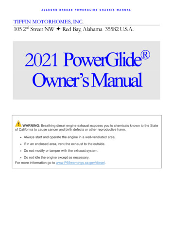
B R A K ES Y S T E MBrake SystemFigure 2-1: Rear Brakes Front brakes are air applied drum- Two large 15 x 4” drum brakesRear brakes (Figure 2-1) double as parking brake-Park brakes are spring applied-Two large 15 x 8.625” drum brakes-Park brake remains applied even if air pressure is lostIf air pressure is lost- A buzzer and warning lamp will alert youChassis is equipped with automatic slack adjusters (Figure 2-2)-No brake adjustment requiredFigure 2-2: Automatic Slack AdjusterThe rear brakes on the PowerGlide chassis are also used as the parking brakes. This provides you the holdingpower of two large drum brakes to prevent your coach from rolling, even when fully loaded on a 20% grade.A decrease in air pressure will not cause an immediate loss of brakes. If a leak develops in the air system whiledriving (at approximately 60 to 65 PSI), you will be alerted via a light on the instrument panel and an audiblealarm. As you apply the brakes, the air supply holding the park brakes in the released position will gradually be2-2
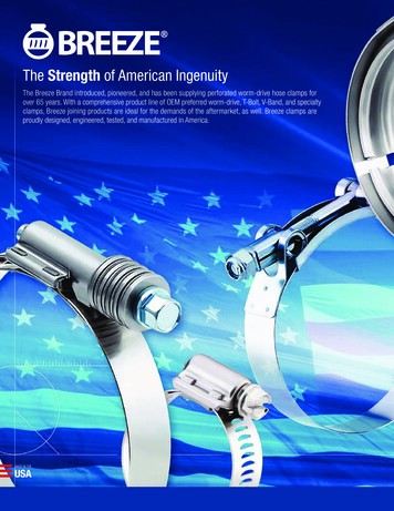
B R A K ES Y S T E Mdepleted. When fully depleted (approximately 40 PSI to 45 PSI), the rear brakes will set. This allows yousufficient time to pull over to the side of the road.NOTE: The rear brakes have dual chambers – one for the service brakes and one for the park brake. Theservice brakes are air applied and spring released. The park brake is spring applied and air released.The brake system is equipped with automatic slack adjusters that avoid the need to manually adjust your brakes.Each time you step on the brake pedal, if adjustment is needed, the adjusters will take up the slack.Compressed Air SystemTank DrainsFigure 2-3: Tank DrainsThe compressed air system is comprised of two air storage tanks. The primary tank stores and supplies air forthe rear brakes, the secondary tank stores and supplies air for the front brakes.When air is compressed it becomes hot. As it cools, condensed moisture forms in the system. The air system isequipped with an air dryer to remove most of this moisture. The dryer has an automatic moisture ejector thatreleases the trapped moisture back into the atmosphere. However, some moisture will form in the systembeyond the dryer, and make its way into the storage tanks. As moisture collects in the primary and secondarytanks, it displaces the area needed for air storage, thus requiring that the tanks be drained periodically.2-3
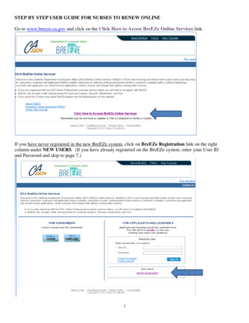
B R A K ES Y S T E MThe air system is equipped with air tank drains conveniently located in the left rear storage compartment(Figure 2-3). There is one drain for the primary tank and one for the secondary tank. These drains should beopened daily for a few seconds to remove any moisture trapped in the tanks.Air DryerFigure 2-4: Haldex Dryest Air DryerThe Tiffin PowerGlide chassis air brake system features a Haldex Dryest air dryer (Figure 2-4), which removesthe condensed moisture from compressed air. The air dryer is equipped with a desiccant cartridge that needs tobe changed every 36 months. The dryer is located on the passenger side, in the forward rear box next to theA/C condenser (behind the rear axle).WarningAir tanks should be bled of all pressure any time you perform work on the air system.2-4
S C H E D U L E DM A I N T E N A N C EChapter3Scheduled Maintenance3-1
S C H E D U L E DM A I N T E N A N C EScheduled MaintenanceSERVICE INTERVAL1,000)(Miles xDaily5101520Required Fluids, Lubricants, and ProceduresAir System:Air DryerXInspect for leaks and blockage of purge valve (9)Air IntakeXInspect for blockage at intake screen on rear capAir FilterXCheck restriction indicator - replace filter as needed (6)Primary Air Tank ReservoirXDrain condensation dailySecondary Air Tank ReservoirXDrain condensation dailyBrake Systems:ABS SensorsXClean sensors & adjust into hub rings. (1)Brake Pads, Rotors, Shoes & DrumsXInspect pads, shoes, rotors & drums for wear and cracks. (1)Slack AdjustersXInspect slack adjuster for proper adjustment & grease.Brake Hoses/Whips, Front & RearXInspect for leaks, & cracking.A/C Condenser FinsXInspect for blockage and wash clean every 10k or as neededCharge Air Cooler FinsXInspect for blockage and wash clean every 10k or as neededFan & Fan ShroudXInspect for blockage and cracks.Radiator Fins/GrillXInspect for blockage and wash clean every 10k or as neededRadiator Hoses & PipesXInspect for kinks, chaffing wear and leaks.Cooling Systems:Coolant LevelXCheck for correct level in sight glassCoolant LeaksXInspect for visual signs of coolant on the groundElectrical Systems:Rear Electrical CompartmentXCheck for loose fuses and cablesFront Electrical CompartmentXCheck for loose fuses and cablesGenerator CablesXCheck for loose red & black cables connected to generatorAlternator BeltBatteriesXCheck for correct tension and wearXCheck for loose lugs / remove any corrosion3-2
S C H E D U L E DM A I N T E N A N C EScheduled MaintenanceSERVICE INTERVAL(Miles x 1,000)Daily5101520Required Fluids, Lubricants, and ProceduresEngine Systems:Engine Drive Belt TensionXInspect belt & tension.Engine Oil FilterXReplace engine oil filter per engine manual (1)Engine OilXChange engine oil per engine manual (1)Exhaust Muffler & PipingXInspect for pinholes, rust and leaks.Diesel FuelAlways use ultra low sulfur fuel onlyFuel Tank Vent LinesXFuel Tank & LinesXInspect for "P" traps that may cause air locks and slow fillingInspect for leaks around fuel inlet nipples and hoses.Engine CoolantChange engine coolant per engine manualPrimary Fuel FilterXReplace fuel filter per engine manual (8)Secondary Fuel FilterXReplace fuel filter per engine manual (8)Steering Systems:Drag LinkXInspect castle nuts for looseness & lube rod ends w/NGLI #2 greaseSteering Gear ArmXInspect for looseness.Steering GearXInspect mount bolts for looseness & hydraulic hoses for leaks.Steering Gear PumpXInspect for hydraulic hose leaks at fittings.Steering Shaft U-JointsXInspect for loose fasteners & lube bearings w/NGLI #2.Steering Shaft BootXInspect for clearance between boot & shaft, lubricate w/ NGLI #2 grease.Suspension & Axles:Coach AlignmentXAlign coach as needed (4)Front Ride Height AdjustXInspect to make sure coach is level to ground if not see a service center.Rear Ride Height AdjustXInspect to make sure coach is level to ground if not see a service center.Ride Height Valve LinkagesXGrease linkage grommets w/D.A. Stewart Aqualube.Air Suspension BagsXInspect for leaks at fittings and inspect bags for leaks or cracksFront Axle BearingsXCheck fluid level through sight window, if low, repair leaks as necessary (1)Front Axle Tie Rods - InspectXInspect for loosenessFront Axle Tie Rods LubricateXLubricate W/NGLI # 2 greaseFront Axle King PinsXLubricate W/NGLI #2 greaseFront & Rear ShocksXInspect for leaks on shock tube, replace as neededRear Axle LubeWheel Lug TorqueXXInspect for leaks & check fluid level. Use synthetic oil only 75W90 (3)Re-torque all wheels nuts - Torque 450-500 lbs (2)3-3
S C H E D U L E DM A I N T E N A N C EScheduled MaintenanceSERVICE INTERVAL(Miles x 1,000)Daily5101520Required Fluids, Lubricants, and ProceduresSuspension & Axles:Automatic Slack AdjustersXLubricate W/NGLI #2 greaseSlack Adjuster Cam ShaftsXLubricate W/NGLI #2 greaseSlack Adjuster Clevis PinsXInspect for wear in clevis pin and cotter pins. Replace as necessaryXInspect u-joints & safety strap for loose bolts & wear, lubricate w/NGLI #2 greaseTransmission & Driveline:Drive ShaftTransmission FluidReplace fluid at 150,000 miles or 48 months whichever occurs first. (5)Transmission FiltersReplace filters at 50,000 miles or 24 months whichever occurs first. (5) (7)(1) Replace / inspect at stated mileage interval or every 6 months whichever occurs first(2) Re-torque all wheel nuts after the first 100 miles, then every 10K miles thereafter.(3) Factory filled with synthetic oil. Do not mix with mineral oils.(4) For best tire life and handling, alignment of front axle is recommended every 15K miles.(5) Factory filled with TranSynd. To maintain these service intervals, fluid must not be mixed with Dexron or other fluids.(6) Replace filter when indicator shows 25 inches or every two years whichever occurs first.(7) Control Main Spin-on Filter initial change required at 10,000 miles.(8) Replace at stated mileage interval or every 12 months whichever occurs first.(9) Replace desiccant cartridge every 36 months.3-4
S C H E D U L E DM A I N T E N A N C ELubrication Points3-5
S C H E D U L E DM A I N T E N A N C ELubrication Points3-6
S C H E D U L E DM A I N T E N A N C ELubrication Points3-7
S C H E D U L E DM A I N T E N A N C ELubrication PointsNO.ComponentsRemarksTotal2King PinsTwo grease fittings; oneon top and one onbottom of knuckle pin.Lubricate both sides ofsuspension.43Tie RodsOne grease fitting per tierod.25Main Driveshaft6Automatic SlackAdjusters7Rear Brake CamshaftBracket8Drag LinkTwo grease fittings perdrag link; one on eachend.29Steering ShaftThree grease fittings;lubricate both universaljoints & slip joint.3Three grease fittings;lubricate both universaljoints & slip joint.One grease fitting oneach slack adjuster. Oneadjuster on each side ofthe rear axle.One grease fitting oneach bracket; Pump ingrease until it appears atthe slack adjuster end ofthe bracket. Lubricateboth sides of the rearaxle.3-8322
S C H E D U L E DM A I N T E N A N C EMaintenance PartsFuel Filter Kit Contains Primary and Secondary FiltersNavistar part #1876533C93 KitTiffin Part # 5018861Engine Oil FilterNavistar part #1870752C1 KitTiffin Part # 5018862Engine Air FilterParker / Racor #094973004Tiffin Part # 5011482Transmission FilterAllison part#29539579Tiffin Part # 5018863Air Compressor BeltNavistar part #1847509C1Tiffin Part # 5013853Alternator / Fan Drive BeltNavistar part #1832193C2Tiffin Part # 50138513-9
S C H E D U L E DM A I N T E N A N C EFor assistance with yourTiffin PowerGlide Chassis Please contact one of the followingChassis Specialists at Tiffin Motorhomes, Inc.256-356-8661Plant ManagerGary Harris, extension 2288ServiceAnson Adams, extension 2173PartsBobby Luther, extension 2382Mechanical EngineerBrad Warner, extension 2267Electrical EngineerChris Struzik, extension 2363Please have your Chassis VIN # availablewhen you call.3-10
P R E - T R I PI N S P E C T I O NChapter4Pre-Trip Inspection4-1
P R E - T R I PI N S P E C T I O NPre-Trip Inspection Check fluid levels & add as necessaryCheck tire inflation pressureLook for fluid leaksBefore starting your motor home daily, a few things must be checked. By doing so, you ensure that a safe trip isin order and lessen your chances of experiencing difficulties while on the road. Check the tires for proper inflation pressure and any damage. Also check the inner duals. Refer to theair pressure charts in this manual for proper inflation pressures. Look for fluid leaks under the motor home. This can prevent any serious problems from occurringlater. Check the coolant level in the reservoir and add a 50/50 mix of coolant and water if necessary. Thisreservoir can be found on the rear of your vehicle. Check ELC (Extended Life Coolant Extender) and freeze point every 30 months or 150,000 miles.Recharge as required.CautionIf the water temperature in your engine is greater than 120 degrees, do not remove theradiator cap! You could be severely burned. Approximate COOLING SYSTEM CAPACITIES – does not include the heater core or otherauxiliary systems added by coach manufacturerNavistar Maxxforce 7 – Rear radiator 52 quarts or 13 gallonsCheck transmission fluid levelCheck engine oil levelCheck for small animals in engine compartment, such as squirrels and catsCheck the power steering fluid reservoirCheck fuel/water separatorMaxxforce 7 Check fuel/water separator and drain any water or contamination that may be present.4-2
P R E - T R I PI N S P E C T I O NAfter you have completed your inspection, you may now start your engine. Turn the key to the run positionand wait for the wait to start light (in some cases it may read “Inlet heater”) to turn off. You may now start theengine. Never use ether or any other starting fluids to start the electronic engine. The inlet heater canignite the fumes and cause an explosion in the air inlet system. Once you have started the engine,monitor your gauges carefully. Make sure that the oil pressure rises within 15 seconds. If it does not, shut downthe engine and call a repair facility to determine the cause.Figure 4-1: Filter Restriction Indicator Check air filter restriction indicator (Figure 4-1)Brand New Air Cleaner10” to 12” of Vacuum Engine air cleaner element should be changed when the air inlet restriction indicator reaches 25 inchesof vacuum or every two years, whichever occurs first. Reset after engine starts for true reading.4-3
I N S T R U M E N T S&C O N T R O L SChapter5Instruments & Controls5-1
I N S T R U M E N T S&C O N T R O L SDPS Instrument Cluster OperationSleep ModeDPS is in sleep mode when battery voltage input is high, ignition key is off and wake-upinputs are not active. In this state DPS electronics are at minimum power consumption.The system exits sleep mode when one of the following wake-up inputs becomes active. Ignition key inputRight and Left signal light inputs (hazard lights)Limited modeIn limited mode the ignition key is off and the DPS offers functionality for: HAZARD WARNING LIGHTSThe right turn signal input is a wake-up input. When active the DPS will wake-upand check the status of the left signal input, and if active, will turn ON the right andleft turn signal indicators.oRun modeThe DPS enters Run mode when the ignition key input is switched to high (active). Thisevent initiates the self test routine, which takes approximately 5 seconds to complete.When the ignition input goes inactive, the DPS will drive all gauge pointers to zero exceptthe fuel gauge.Self TestGAUGESGauge pointers sweep to full scale. The pointers will return to zero position and then tooperational position.LCDThe LCD will turn all segments on for one second, off for one second and then display theTiffin Motorhomes logo until the start-up routine is completeWARNING LIGHTSThe warning lights will turn on and then go to operational state at the end of the self test.AUDIBLE ALARMA steady alarm tone will be generated and then go to operational state at the end of theself test.5-2
I N S T R U M E N T S&C O N T R O L SGaugesSPEDOMETERThe speedometer is scaled from 0 to 140 and is for both English and Metric units. Theindicator of the selected units is beneath the speedometer needle. The configuration toselect units can be accessed through the set-up menu or by simultaneously pressing theMODE and TRIP buttons. The factory default is English units.Data sourceJ1939Scale: Linear0 0 MPH/Km/h140 140 MPH/Km/hWLNoWL TriggerNoAud. AlarmNoTACHOMETERThe Tachometer is scaled from 0 to 4 with a X1000 multiplier.Tachometer 2.4” gauge upper left corner.Data SourceJ1939Scale: Linear0 0 RPM4 4000 RPMWLNoWL TriggerNoAud. AlarmNoFUELThe fuel gauge is on a linear scale with E indicating empty and F indicating full. Themiddle of the gauge indicates 50% fuel tank level. The low fuel warning light comes onwhen fuel level drops to 12.5% level. The low fuel warning light turns off when the fuellevel reaches 18%.A LOW GENERATOR FUEL warning will be displayed on the LCD when the generatorand ignition inputs are active and the fuel drops to 15%Data sourceFuel SenderScale: LinearE Empty½ 50% tank levelF FullWLLCDIconWL TriggerOn Fuel 15%On fuel 12.5%Off fuel 18%Aud. Alarm44AIR PRESSURE 1 / AIR PRESSURE 2Data sourceAir PSI TransducerScale: Linear0 0 PSI150 150 PSIWLIcon5-3WL TriggerOn if press 65 PSIOff if press 72 PSIAud. Alarm1
I N S T R U M E N T S&C O N T R O L SIcon Lights IndicatorsLEDFunctionTriggerFlashAlarmLED1Low AirFor both front and rear pressOn if pressure is 65 PSIOff if pressure is 72 PSISteady1LED2LowBatteryJ1939 msg:if Batt V is 10.8 VoltsSteady4LED3CheckTransBased on J1939 messagesstandardSteady4LED4ABSBased on J1939 messagesstandardSteady4LED6Seat BeltOn for 30 sec when ignition swturns onSteadyNoneLED7Park BrakePark Brake Input ActivePark Brake Input Inactive,Service Brake Input Inactive andcurrent gear NeutralSteadyQuickFlashNone2LED8Failure /malfunctionON when a priority message isactive.See PRIORITY MESSAGESSteadyNoneLED9StopEngineBased on J1939 proprietarymessageSteady3LED10Change OilBased on J1939 proprietarymessageSteadyNoneLED12CheckEngineBased on J1939 proprietarymessageSteadyNoneLED13HESTBased on J1939 messagesstandardSteadyNoneLED14DPFBased on J1939 messagesstandardSteadyFlashNoneNoneLED17Left TurnOn when left turn input is activeSteady55-4Color/Icon
I N S T R U M E N T S&C O N T R O L SLED18CruiseControlBased on J1939 messagesstandardSteadyNoneLED20Wait ToStartBased on J1939 messagesstandardSteadyNoneLED21Water inFuelBased on J1939 messagesstandardSteady4LED22Low FuelOn fuel 12.5%Off fuel 18%Steady4LED23High BeamOn when high beam input isactiveSteadyNoneLED24Right TurnOn when right turn signal isactiveSteady5LED25MPHOn when English units isselectedSteadyNoneLED26KM/HOn when metric units is selectedSteadyNoneAudible AlarmsAudible AlarmFreq 1T1Period1900 HzContinuous2700 Hz / 750Hz160 ms / 160msContinuous3900 Hz160 ms2.2 S4900 Hz160 msOnce no repeat5Turn Signal ClickTurn signal clickNote: Alarm 1 has the highest priority and alarm 5 the lowest. Highest alarms override any active lower alarm.5-5
I N S T R U M E N T S&C O N T R O L SDATA COMMUNICATIONThe DPS communicates with the vehicle through the J1939 network. See appendix A fora list of supported messages.COMUNICATION ERRORSThe DPS LCD shall report “not received” parameters for Engine, Transmission and ABS ifthe data is not received for 2.5 seconds on the J1939 network. The LCD messages will bedisplayed as: “ENGINE COMM FAIL”“TRANS COMM FAIL”“ABS COMM FAIL”The failure/malfunction LED will also be active for this condition.The message(s) and LED will turn off once communication is reestablished.SERVICE BRAKEThe service brake status will be broadcasted on the J1939 network. The service brakeoutput is hardwired into the IP as active low input.PARKING BRAKEThe parking brake status will be broadcasted on the J1939 network. The parking brakeoutput is hardwired into the IP as active low input.LCD MESSAGESThe LCD gives visual operational information and diagnostics information to the operator.DRIVE MODE SCREENAfter key on and with no active fault messages the LCD displays odometer, time and theselected main menu items.LCD TIME CLOCKThe LCD will display current time on the right end side of the display. Time can beaccessed and adjusted through the setup menu Clock Adjust.5-6
I N S T R U M E N T S&C O N T R O L SODOMETERThe odometer range is 0.0 - 9,999,999.9. The resolution is 0.1 miles/kilometers. Distancevalue is displayed based on engine data transmitted on the J1939 network.TRIP 1 ODOMETERTrip 1 is operator selectable through the main menu. The reading range is 0.0 – 9,999.9with a 0.1 miles/kilometers resolution.TRIP 2 ODOMETERTrip 2 is operator selectable through the main menu. The reading range is 0.0 – 9,999.9with a 0.1 miles/kilometers resolution.PRIORITY MESSAGESPriority messages, when active, will replace the selected menu reading in the secondLCD line. In the event that multiple messages are active each message will be displayedfor 2 seconds, followed by the second warning message for 2 seconds. Thefailure/malfunction LED will also be active for this condition. Messages can beacknowledged by pressing the TRIP button; this removes the message off the screen, butthe failure/malfunction LED will remain active as long as the message trigger is present.PRIORITY MESSAGESLCD MessageTriggerAcknowledgeTurns off ifAlarmEngine CommErrorNo data communicationPress TRIPCommunicationis reestablished4Trans CommErrorNo data communicationPress TRIPCommunicationis reestablished4ABS Comm ErrorNo data communicationPress TRIPCommunicationis reestablished4Turn Signal OnTurn signal on for morethan one mileTurn signal backto off positionTurn signal backto off positionnoneOil pressure(number value)Oil PSI exceeds normalvaluePress TRIPMessage clears4Eng coolanttemperature(number value)Engine coolant exceedsnormal valuePress TRIPMessage clears4Jacks DownOn when jacks down,ignition, and parking brakeinputs are activeFailure LED is OFFnoneMessage clearsnoneJacks DownOn when jacks down andignition are active andparking brake input isinactivenoneMessage clears2NOTE: Jacks Down input is currently not being utilized.5-7
I N S T R U M E N T S&C O N T R O L SRolling AlarmWhen the vehicle is in neutral and the park brake and service brake are not active, analarm will sound to indicate a rolling hazard. An alternating 2 tone continuous alarm willsound and the brake icon will flash at a rapid rate (2Hz). This alarm can not beacknowledged.Main MenuPressing the MODE button will access the main menu. While in the main menu, pressingMODE or TRIP buttons will scroll through the menu items. If there are no button pressesfor 5 seconds, the main menu will be exited and the position select window will bedisplayed. Pressing both buttons simultaneously will also exit the main menu and displaythe position select window. If a button press is not detected within 5 seconds, the positionselect window will be exited and the drive mode screen will be displayed. The drive modedisplayed items will be unchanged if a location selection has not been made.The following is the list of available parameters. Engine TemperatureChassis BatteryOil pressureTransmission Oil TemperatureCheck List (see Appendix B for the checklist)Trip 1 DistanceTrip 2 DistanceInstantaneous Fuel EconomyAverage Vehicle SpeedAverage Fuel EconomyEngine Hours5-8
I N S T R U M E N T S5-9&C O N T R O L S
I N S T R U M E N T S&C O N T R O L SSet-up MenuThe Set-up Menu is accessible when the ignition key is ON, and vehicle speed is lessthen 3.1MPH (5Km/h). Pressing and holding the MODE button for 5 seconds will enter theset-up menu. While in the set-up menu, pressing the MODE or TRIP buttons will scrollthrough the menu items. If no button is pressed for over 5 seconds the highlighted optionwill be selected. Pressing both buttons simultaneously will also select the highlightedoption.The following is the list of available set-up options. ContrastRestore DefaultsUnitsSoftware VersionCluster TestingClock adjustExit MenuContrastT for M for -Displayed on LCDRestore DefaultsT to restore defaultsM to exitDisplayed on LCD5-10
I N S T R U M E N T S&C O N T R O L SUnitsT to changeEnglishM to exitDisplayed on LCDSoftware VersionSoftware Version928630v00 21M to exitDisplayed on LCDCluster TestingGauge TestEach gauge will be driven to the 0%, 50% and 100% position, pausing at each position forapproximately 3 seconds. The LCD will display the position that the gauges should be in.Pressing the MODE button will exit this test and return to the Cluster Testing menu.Warning LightsEach icon light will be turned off at the beginning of the test. The LCD will display whichicon is being tested and whether it is ON or OFF. The test will continually cycle through allof the icons until the test is exited by pressing the MODE button.Graphic testTurns on the Tiffin logo and inverts the colors every two seconds. Pressing the MODEbutton will exit this test and return to the Cluster Testing menu.Backlight TestAll backlighting will be cycled through 0%, 50% and 100% as indicated by the LCD.Pressing the MODE button will exit this test and return to the Cluster Testing menu.Speaker TestThe 4 alarm tones will be sounded for approximately 10 seconds each. The test willcontinually cycle until the test is exited by pressing the MODE button.5-11
I N S T R U M E N T S&C O N T R O L SDigital InputsThe digital inputs will be listed by their function and the current status of each input will beindicated by an ON or OFF. Pressing the MODE button will exit this test and return to theCluster Testing menuAnalog TestThe analog inputs will be listed by their function and the current value being detected willbe indicated.Power Train FaultsAll DM1 messages that are active will be displayed. The source of the fault, the SPN andFMI will be indicated. If there are no active faults, the text “No Faults” will be displayed.Pressing the MODE button wi
ALLEGRO BREEZE POWERGLIDE CHASSIS MANUAL . TIFFIN MOTORHOMES, INC. Allegro Breeze Chassis Owner's Manual Tiffin Motorhomes, Inc. 105 2. nd Street NW, Red Bay, AL 35582 U.S.A. Telephone 256.356.8661 Facsimile 256.356.8219. E-Mail: info@tiffinmotorhomes.com . as possible at the time of printing.