Transcription
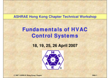
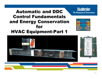
Automatic and DDCControl Fundamentalsand Energy ConservationforHVAC Equipment-Part 11-1
DisclaimerThis presentation was prepared specifically for use ascollege training materialmaterial. It shall not be modifiedwithout the consent of the authors.This presentation represents sponsored researchactivities. Neither the Client nor Battelle warrantsthe accuracy, completeness or usefulness of theinformation. Reference herein to any specificcommerciali l product,d t process or servicei bby ttradednames or manufacturer does not constitute anendorsement or recommendation.PNWD-SA-88341-2
DDC Controls and Energy Conservation forHVAC EquipmentEq ipment - Agenda1.22.3.44.5.6.7.8.PNWD-SA-8834Introduction of DDC Controls ProjectHVAC CControlt lPPrinciplesi i lCommunication Standards and NetworksVendor Examples of DDC Software Programming andOperator InterfacingTypical Rooftop and Central AHU HVAC ControlSystems and ApplicationsSystem Maintenance and Service of DDC ControlsAvoidingg Common Control Problems and Fixingg theProblemsCalibrating and Verifying Energy Savings of the DDCControls1-3
Part 1HVAC Control Principles1. Intent of Battelle Pacific NW Division involvement2. Purpose of Controlspof Control Systemsy3. Keyy Components4. Control Loops, Open vs. Closed Loops5 Terminology5.6. The Control Cycle and Control Actions7 The7.Th EnergyESourcesSforf ControlC t lSSystemst8. DDC Point TypesPNWD-SA-88341-4
Part 2Control Applications, Networks,Programming, Maintenance, andEnergy Savings1. DDC Control Applications2. DDC Networks and Architecture3. Communication Standards and Networks4. Vendor Examples of DDC Software Programmingand Operator Interfacing5. System maintenance and service of DDC controlsg DDC controls to save energygy6. UsingPNWD-SA-88341-5
Section 1Introduction of DDC Controls Project Purpose of this project is to provide HVACeducationaldtil materialst i l tto WWashingtonhi t StStatetcommunity colleges to educate students who havechosen or may chose career paths related to HVACservicing and building energy management fieldsPNWD-SA-88341-6
Section 2HVAC Control PrinciplesThe Purpose of Temperature Controls Control systems are the “brains” of HVAC equipment tomaintaini t i hhuman comfort.f t PiPicturedt dbbelowliis an AHU ththattserves only one zone. This type of AHU is called a singlezone AHU. In the example, a temperature sensor (stat) sendsa signalil tto a controlt l panel,l whichhi h sendsd a signalil tto a valve.lCourtesy TAC Controls/Schneider ElectricPNWD-SA-88341-7
Section 3KKeyCComponentst off a CControlt lSystem Include:Courtesy TAC Controls/Schneider ElectricPNWD-SA-88341-8
SensorsModern HVAC Sensors Include: Humidity and temperature transmitters CO2 for indoor air quality (IAQ) utilizingddemandd controlt l ventilationtil ti Power meters Branch circuit monitors Energy metersCourtesy Veris IndustriesPNWD-SA-88341-9
Sensors A sensor monitors and measures a variable. TheHVAC variables are temperature, humidity, flow, andpressure Different types of signals are produced bypressure.different types of sensors. They include:– Electric sensors– Pneumatic sensors– Electronic sensorsAn example of a sensor is shown here. While it mayappear to be a thermostat, it is a remote sensor witha remote setpoint dial.dial The controller is in anotherlocation.Courtesy TAC Controls/Schneider ElectricPNWD-SA-88341-10
Pneumatic Sensors/Transmitters Pneumatic controls sensors or transmitterssense the variable and produce a 3 psig to 15psig (pound per square inch, gauge), [20 kPa(kiloPascals) -105 kPa] signal over a particulartransmitter's range.Courtesy Johnson ControlsPNWD-SA-88341-11
Electronic Sensors Include: Resistance sensors are resistance temperaturedevices (RTDs)(RTDs), and are used in measuringtemperature. Examples are Balco elements, copperplatinum, 10K thermistors, and 30K thermistors. Voltage sensors could be used for temperature,humidity and pressure. Typical ranges are 0 to 5Vd (VVdc(Voltslt didirectt current),t) 1 tto 11 VdVdc, andd 0 tto 10Vdc. CurrentCt sensors couldld bbe usedd ffor ttemperature,thumidity, and pressure. The typical current range is4 to 20 mA ((milliamps).p )PNWD-SA-88341-12
1000Ω (Ohms) Balco PTCElectronic Temperature Sensors The resistance outputs of a electronic Balco temperaturesensor follow the diagrams below: When 1000 ohms is measured across the Balco element, thetemperature is approximately 70 F (21 C).(21 C) As the temperatureincreases, the resistance changes 2.2 ohms per 1 F (3.96ohms per 1 C). In a Balco temperature sensor, as thettemperaturetincreases,itheth resistancei tincreasesiproportionallytillin a positive direction. This is known as a positive temperaturecoefficient (PTC) sensor. However, many temperature sensorsare consideredid d ththermistors,i tandd performfas NNegativetitemperature coefficients (NTC).PNWD-SA-88341-13
Comparisonof Common Temppp SensorsCourtesy Omega ControlsPNWD-SA-88341-14
Controllers Can Include:Electric ControlsPneumatic ControlsDDCControlsElectronic ControlsPNWD-SA-8834Courtesy Johnson, Honeywell, and Alerton Controls1-15
Controllers basic principlesthe controller receives the inputAnd processes an outputPNWD-SA-88341-16
Electronic Control SystemyCourtesy Honeywell ControlsPNWD-SA-88341-17
Pneumatic Controller System“Branch”Branch or sorDamperOperator“Main” or Supplypp alveCourtesy Northwest Energy Efficiency CouncilPNWD-SA-88341-18
The DDC controller receives the inputfrom the sensor, performs a logicfunction and processes an outputfunction,Courtesy DDC Online OrgPNWD-SA-88341-19
Controller Action-Direct or ReverseIllustrationCourtesy Honeywell ControlsPNWD-SA-88341-20
Controller Direct Action-IllustrationCourtesy TAC Controls/Schneider ElectricPNWD-SA-88341-21
Controller Direct Action-Illustration This relationship between the input to a controller(temperature) and its output (current) can bedisplayed on a graph as follows:Courtesy TAC Controls/Schneider ElectricPNWD-SA-88341-22
Controller Reverse ActionAction-IllustrationIllustrationCourtesy TAC Controls/Schneider ElectricPNWD-SA-88341-23
Controller Reverse ActionAction-IllustrationIllustration This relationship can is displayed on a graph asfollows:Courtesy TAC Controls/Schneider ElectricPNWD-SA-88341-24
Controlled DevicesControl Valves– two-way Control ValvesUsed with differential pressure (DP) sensors and VSD pumpsystems on primary and secondary loops– three-way (mixing or diverting)– PressurePress re independent control valvesal esAutomatic dampersDamper operatorsVSDs: variable speed drivesCourtesy BelimoPNWD-SA-88341-25
Controlled DevicesValvesDiverting ValveMixingg ValveTypical Single - and Double-SeatedTwo-Way ValvesTypicalTi l Three-WayThW MixingMi iand Diverting ValvesCourtesy BelimoPNWD-SA-88341-26
The Present Control SystemsyUse control valves that are: PressurePressure independent control valves No Cv required, reduced pumping costs, higherefficiency, easy to balance.Courtesy Flow Control ValvesPNWD-SA-88341-27
Examples of 2-Way and 3-WayControl ValvesNorthwest Energy Efficiency CouncilPNWD-SA-88341-28
Dampers: Types, Actuators,and Characteristics– Economizers on many central AHUs arecustom orderedcustoo de ed foro thet e job specificspec crequirements– Economizers on packaged RTUs arenormally ordered as an option with thepackage– Control Dampers Can Be Either:P ll l or opposedParalleldddampersParallel BladePNWD-SA-8834Opposed Blade1-29
Economizer Damper Actuator Typesare either:PneumaticPNWD-SA-8834ElectricElectronic1-30
Economizer Damper Actuatorswill have either direct connect actuators bolteddirectly to the damper or they will be installed with ashaft and linkage arrangement (more prone to fail)Direct Connect ActuatorPNWD-SA-8834Damper Connected to ActuatorVia Shaft and Coupling1-31
Parallel Blade Damper Characteristicspoor linear controlhave pCourtesy T.A. & Co.PNWD-SA-88341-32
Opposed Damper Characteristicshave better linear controlCourtesy T.A. & Co.PNWD-SA-88341-33
Damperp Actuators can be Controlled byy: Voltage (0-10Vdc or 2-10Vdc) Current (4-20mA) FloatingFl ti pointi t (binary(bipulsel tto open or close)l) PWM-pulse width modulated Resistance (0-135(0 135 ohms)Example of analog control using 4-20mA or 2-10VdcPNWD-SA-8834Courtesy Belimo1-34
Electronic VariableFFrequencyDrivesDi(VSDs)(VSD ) Vary frequency of motor to control speed Often called VSDs,VSDs VFDs,VFDs or ASDsPNWD-SA-88341-35
DDC control systems have variableffrequencydrives ((VFDs)) asstandard equipment on: CoolingC li towers AHU’s and VAV fans Pumps ChillersPNWD-SA-88341-36
Variable Speed DrivesCourtesy ABB ControlsPNWD-SA-88341-37
Review of the Key ControlComponentsExercise-identify the sensors, controllers, andcontrolled devicesCourtesy TAC Controls/Schneider ElectricPNWD-SA-88341-38
Review of the Keyy ControlComponentsExercise-connect the sensor, controller, andcontrolled device in the proper order.orderCourtesy Alerton and BelimoPNWD-SA-88341-39
Review of Control ActionExercise-theExercisethe control drawing below has adirect acting controller, with a NO valve. Showthe correct action with arrows at eachcomponentt whenhusedd ffor coolinglimode.dActingCourtesy TAC Controls/Schneider Electric and BelimoPNWD-SA-88341-40
Review of Control ActionExercise-Circle the correct answer.Courtesy TAC Controls/Schneider ElectricPNWD-SA-88341-41
Review of Control ActionExercise Circle the correct answer.Exercise-CircleanswerCourtesy TAC Controls/Schneider ElectricPNWD-SA-88341-42
Review of Control ActionExercise-Circle the correct answer.Courtesy TAC Controls/Schneider ElectricPNWD-SA-88341-43
Review of the Key ControlComponentsExercise-Identify the parallel vs. opposed bladedampers and the 3-way mixing vs. divertingPNWD-SA-8834Courtesy Belimo1-44
Section 4Basic Control Loop PrinciplesControllers can be either“ l“closed”d” or ““open””LLoop– ClosesClloopslprovideid ffeedback-gooddb kd controll– Open loops have no feedback-poor controlPNWD-SA-88341-45
Basic Closed-Loop-ExampleThe sensor feeds back to the controllerCourtesy DDC Online OrgPNWD-SA-88341-46
Open Loop Controlshave no feedback to the controllerCourtesy DDC Online OrgPNWD-SA-88341-47
Closed vs. Open Loop ControlIllustrationNotice, averaging bulb is closed loop in supply air,but T-STAT between filter and coil is open loop.Courtesy Northwest Energy Efficiency CouncilPNWD-SA-88341-48
Section 5Control TerminologySetpoint, offset, and control pointThrottling rangep and rangegSpanAuthorityCalibrationAnalog and digitalThermostat as sensor-controllerPNWD-SA-88341-49
SetpointSetpoint is the desired condition of a variable that is to bemaintained, such as temperature. In the example below,75 degrees FF. is the room temperature setpoint that thebuilding occupant desires.Courtesy TAC Controls/Schneider ElectricPNWD-SA-88341-50
Control Point and Offset The Control point is the actual temperature being sensed.The control point (temperature) may not be on the setpoint,but instead may be above or below it. Simply stated,setpoint is what you want, while control point is what youget. Offset is the amount of difference between controlpoint and setpoint in a proportional control systemsystem. In theexample below, the offset is approximately 4 F.Courtesy TAC Controls/Schneider ElectricPNWD-SA-88341-51
Throttlingg Rangeg System throttling range (STR) is the change in themeasured variable (i(i.e.,e temperature) that causesthe controlled device to travel from one end of itsstroke to the other.Courtesy TAC Controls/Schneider ElectricPNWD-SA-88341-52
Section 6The Control Cycle and Control Action TwoT positioniti Floating action Proportional actionPI PI PIDCourtesy PECIPNWD-SA-88341-53
Control Cycle GraphCourtesy Northwest Energy Efficiency CouncilPNWD-SA-88341-54
TTwoPositionP itiCControlt lTwo Position control action chart (heating action shown)Courtesy Northwest Energy Efficiency CouncilPNWD-SA-88341-55
TTwoPositionP itiCControlt lRResponsePNWD-SA-88341-56
Floating Action ControlCourtesy Northwest Energy Efficiency CouncilPNWD-SA-88341-57
PProportionaltilCControlt lAActiontiProportional Control ActionCourtesy Northwest Energy Efficiency CouncilPNWD-SA-88341-58
Proportional withI tIntegrallCControlt l (PI)Proportional Plus Integral (PI) Control ActionCourtesy Northwest Energy Efficiency CouncilPNWD-SA-88341-59
PID-ProportionalpPlus Integral & DerivativeProportional Plus Integral Plus Derivative (PID) control actionCourtesy Northwest Energy Efficiency CouncilPNWD-SA-88341-60
Adaptive ControlAdaptive loop tuning provides: Accurate, continuous loop control Faster tuning of loops for energy savings Less wear on valves, actuators, fans, pumps, dampers,VFDs, etc.PNWD-SA-88341-61
Review of Control CyclesExercise; study the drawings and identifythe control loop types as either:2-position, proportional, or PI ControlPNWD-SA-8834Courtesy Northwest Energy Efficiency Council1-62
Review of Control CyclesExercise; identify and circle the closedloop vs. the open loop controls.Courtesy Northwest Energy Efficiency CouncilPNWD-SA-88341-63
Review of Control CyclesyExercise; review the drawing andidentify setpoint, control point, TR,and offset.offsetCourtesy TAC Controls/Schneider ElectricPNWD-SA-88341-64
Review of DDC TerminologyExercise; identify the missing termsCourtesy Northwest Energy Efficiency CouncilPNWD-SA-88341-65
Section 7Control Energy SourcesA power supply or source of energy is needed topower the control systemsystem. Control systems useeither a pneumatic or electric power supply. Pneumatic controls use a compressed gas as asource of energy, typically compressed air. Electric and electronic controls could bepowered by a variety of electrical power suppliesof either alternating current (AC) or direct current(DC).(DC) DDC-Direct digital controls are consideredelectronically powered via a network of controls.controlsPNWD-SA-88341-66
Comparing AdvantagesAnd Disadvantagesof pneumatics and DDC controls Pneumatic control systems Low maintenance, ease of testing Hard to integrate into DDC systems Requires air compressor station DDCDDC – DirectDi t didigitalit l controlt l High accuracy Flexible,Flexible easy to access Programmable Energy management considerations Easy to optimize, reduce kW peaks, schedulePNWD-SA-88341-67
Basic Pneumatic Control SystemThe Air Station ComponentsCourtesy Honeywell ControlsPNWD-SA-88341-68
Basic Pneumatic Control SystemPNWD-SA-88341-69
Conventional PneumaticControl SystemsRequirements: Clean and dry air supply Pressure reducing valve Utilizes pneumatic controllers Pneumatic devicesPNWD-SA-88341-70
Pneumatic Controls Include: Thermostats that can be either: Room type Dead band typesyp Dual pressure type Humidistats Receiver controllers Combine 2 sensors into 1 receiver with resetsetpoint options Utilizes either one pipe or two pipes SensorsPNWD-SA-88341-71
Pneumatic Control of HeatingCoil Control with ResetCourtesy Northwest Energy Efficiency CouncilPNWD-SA-88341-72
Pneumatic Control SystemAccessoriesPneumatic relays: Reversing relay High/low pressure selector Air motion Signal repeatingPneumatic SwitchEP-Electric to Pressure Switch Minimum position EPs and PEsPNWD-SA-8834PE-Pressure to Electric Switch1-73
B i PneumaticBasicPti ControlC t lSSystemtPNWD-SA-88341-74
Example of Pneumatic ControlsCourtesy LAMA BooksPNWD-SA-88341-75
Basic Electric ControlCourtesy Honeywell ControlsPNWD-SA-88341-76
Examplea p e ofo Electricect c ControlsCo t o sfor EconomizersCourtesy Honeywell ControlsPNWD-SA-88341-77
Simple Electronic ControlS tSystemCourtesy Honeywell ControlsPNWD-SA-88341-78
Example of Electronic Control forBasic AHU Economizer ControlCourtesy Honeywell ControlsPNWD-SA-88341-79
Example of Electronic Control forEconomizers with Differential Enthalpyand CO2 Demand Ventilation ControlCourtesy Honeywell ControlsPNWD-SA-88341-80
Section 8-DDC Point TypesInputp and Outputp Point Typesyp ChartInputOutputTwo state information from the building Two state information from DDC fieldinto the DDC field panelpanel to the buildingDi it lDigitalSwitches:On/Off - fans, pumps, lightsDifferential press/proofOpen/Close, two position damperSmoke alarmsControl of twotwo-speedspeed motorsLevel alarmEnergize/de-energize valves forheat/cool changeoversHigh/low pressure alarmFilter statusAnalogVariable information from the buildinginto the DDC control panelVariable information from the DDCcontrol panel out to the buildingTemperature Room duct,Temperature-Room,duct OSAModulate valves,valves dampers,dampers actuatorsHumidities-Room, duct, OSAMotor speed control – VSDsPressure-Static, velocity, totalModulate volume dampersFlow rates-Water and air systemsAdjust air pressure to pressure operateddeviceskWh power, volts, and ampsPNWD-SA-88341-81
DDC Control SystemDigital Input (DI) IllustrationCourtesy DDC Online Org.PNWD-SA-88341-82
DDC Control SystemDigital Input (DI) IllustrationFlow SwitchCourtesy Honeywell ControlsPNWD-SA-88341-83
DDC Control SystemDigital Input (DI) Pulsed SignalIllustrationFlow SwitchCourtesy Verris IndustriesPNWD-SA-88341-84
DDC Control SystemDigital Output (DO) IllustrationTriac Type Digital Output with External RelayTransistor with Pilot RelayCourtesy DDC Online Org.PNWD-SA-88341-85
DDC Control SystemA lAnalogInputIt (AI) IllustrationIll t tiCourtesy DDC Online Org.PNWD-SA-88341-86
DDC Control SystemAnalog Input (AI) IllustrationFor Measuringg Air Flow in FPMCourtesy Dwyer Instruments.PNWD-SA-88341-87
DDC Control SystemAnalog Output (AO) IllustrationFor controllinggappneumatic valveCourtesy TAC Controls/Schneider ElectricPNWD-SA-88341-88
Analogg Outputp (AO)() Damperp Actuatorsare controlled by either a voltage (2-10 Vdc) orcurrent (4-20 mA) signal from the controllerCourtesy BelimoPNWD-SA-88341-89
Examplep of DDC AHU ControlApplication with Point Types IdentifiedCourtesy Honeywell Controls.PNWD-SA-88341-90
ExerciseReview of DDC TerminologyCourtesy TAC Controls/Schneider ElectricPNWD-SA-88341-91
ExerciseReview of DDC TerminologyCourtesy TAC Controls/Schneider ElectricPNWD-SA-88341-92
HVAC Control Principles The Purpose of Temperature Controls Control systems are the “brains” of HVAC equipment to maiti h f tPit dbl i AHUthtintain human comfort. Pictured below is an AHU that serves only one
