Transcription
International Journal of Scientific & Engineering Research, Volume 5, Issue 7, July-2014ISSN 2229-55181Microcontroller ATmega32 Based AutomaticVehicle ControlKanis Fatima1, Md.Abul Hossain2Abstract— This paper proposes novel control architecture for automatic vehicle driving in a dynamic and uncertain traffic environment.In the presentscenario accidents are increasing rapidly. We need to make such a system which can continuously detect obstacle around the vehicle and avoid themfrom collision. We choose ATmega32 microcontroller for the controlling of the system.The implemented design will increase the safety and reliability withreducing the risks of life.Keywords—ATmega 32 microcontroller, Counters, crystal oscillator, IR transmitter, IR receiver.—————————— ——————————1 INTRODUCTIONMicrocontroller Based vehicle is a field of application of automation, which is a modern technology in automobile sector.The 1960's research has generally been focused on softwarecontrol vehicle. Scientists from Europe and America both began work on autonomous vehicles as an area of application ofThe output from this receiver which is a square wave is theinput of the 555 timer. The output of the 555 timer from thepin no- 3 of ATmega32 is fed to the base of the transistorthough a resistor and capacitor. The capacitor 1000 µF whichis used here makes the high output of the 555 timer a constantIJSERrobotics. These projects have been created from passengersized vehicles, as well as small model vehicle [1], [2].line which is always high. The motor winding is connected tothe transitor by 8V supply. In this way the vehicle takes theA 56 kHz signal is generated by a microcontroller program.ATmega32 flash microcontroller has been used which having40 pins . It has 32digital Input & out put port, of which just 7pins have been used in this project.This microcontroller program is loaded on the 40 pin microcontroller ATmega 32. Thevehaicle avoids obstacles which it senses with its active infrared sensors. The IR LED will emit infrared. The sensor is builtwith infrared LED which runs at a speed of 56 kHz. When theinfrared light from the LED is reflected by an object the IR re-decision when it finds a obstacle.2AIM OF THE PROJECT WORK1.To detect existence of any object in left front of the car byinfrared sensors by using radar and doppler principle.2.To detect existence of any obstacle in front of the vehicleby infrared sensors.3.Construct a vehicle which can make Primary decesionbefore collision.4.ceiver senses this.Controlling the vehicle with the front two wheels by twoindividual dc motor according to the position of obstacleor any —— Kanis Fatima has completed her B.Sc. degree from Chittagong University ofEngineering and Technology and is currently working as a Lecturer, Department of EEE, IBAIS University, Bangladesh.She is also pursuing her mastersdegree program in Bangladesh University of Engineering and Technology,Bangladesh, PH: 8801914554750. E-mail: f.kanis@yahoo.com Md.Abul Hossain has completed her B.Sc. degree from Chittagong Universityof Engineering and Technology and is currently working as InfrastructurePower Engineer in Orascom Telecon Limited. PH: 8801939900447. E-mail:shabuddin01@yahoo.com5.By the input of 56 kHz signal from the microcontrollersensors detect the position of obstacle or vehicle then takethe decision whether turn or not and fed the signal to thereceiver TSOP1356 to take the decesion about avoidingobstacle or vehicle by reversing one of the dc motors.IJSER 2014http://www.ijser.org
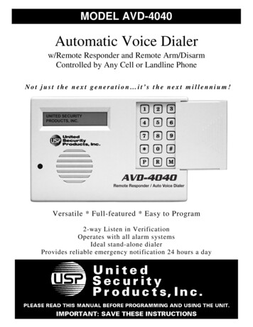
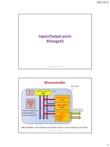
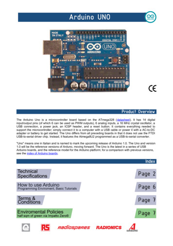
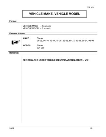
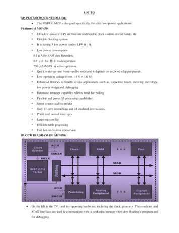
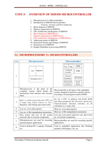
International Journal of Scientific & Engineering Research, Volume 5, Issue 7, July-2014ISSN 2229-55182TSOP1356 is the standard IR remote control receiver series,3 SYSTEM OVERVIEWsupporting all major transmission code.Fig 1 Block diagram of the projectFig 2 IR receiver3.1. IR TRANSMITTERIR-LED is a one kind of led which emittes infrared light likenormal light emitting diode.As like other led it also has two4 ATmega32 MICROCONTROLLERterminal.The large pin is anode and the smaller pin is cath- High-performance, Low-power AVR 8-bit MicrocontrollerIJSERode.It emittes infrared light and reflect the light on any substance same as the principle of visible light.DATA SHEET OF THE IR TRANSMITTER:WaveOrder No.Lens nsparentDarkBlueTransparentWater Clear Nonvolatile Program and Data Memories– 16K Bytes of In-System Self-Programmable FlashEndurance: 10,000 Write/Erase Cycles– 512 Bytes EEPROMEndurance: 100,000 Write/Erase Cycles– 1K Byte Internal SRAM.– Programming Lock for Software Security.Electro–optical characteristicsVf(V)le (mW/sr)Typ.Max.8501.51.8160 mW/sr @ 50mA8501.51.880 mW/sr @ 50mA9401.21.630 mW/sr @ 10mA Advanced RISC Architecture– 131 Powerful Instructions – Most Single-clock Cycle Execution– 32 x 8 General Purpose Working Registers– Fully Static Operation– Up to 16 MIPS Throughput at 16 MHz3.2. IR RECEIVERThe TSOP1356 is miniaturized receivers for infrared remotecontrol systems. PIN diode and preamplifier are assembled onlead frame, the epoxy package is designed as IR filter The demodulated output signal can directly be decoded by a micro- Peripheral Features– Two 8-bit Timer/Counters with Separate Prescalers andCompare Modes.– One 16-bit Timer/Counter with Separate Prescaler, CompareMode and Capture mode. Speed Grades– 0 - 8 MHz for ATmega16L– 0 - 16 MHz for ATmega16 I/O and Packages– 32 Programmable I/O Lines Operating Voltages– 2.7 - 5.5V for ATmega16L– 4.5 - 5.5V for ATmega16processor.IJSER 2014http://www.ijser.org
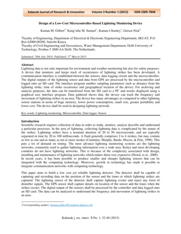
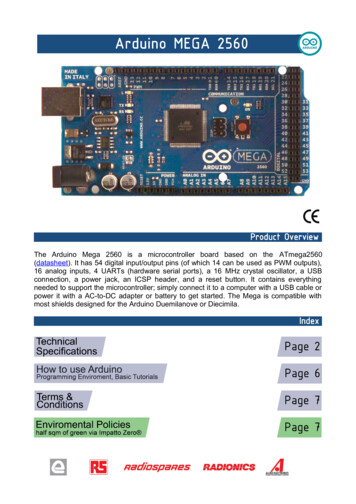
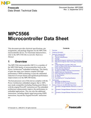
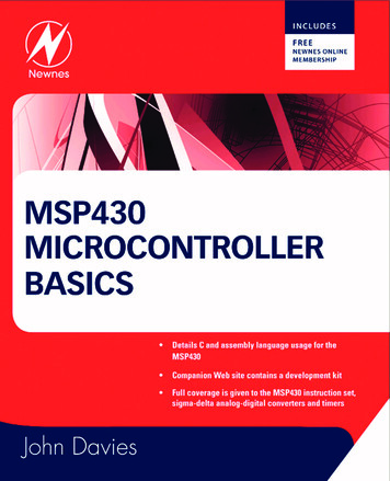
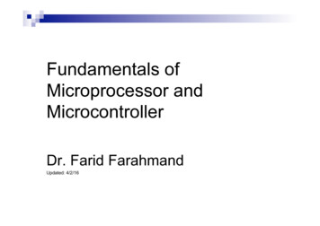
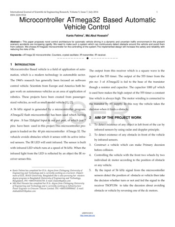
International Journal of Scientific & Engineering Research, Volume 5, Issue 7, July-2014ISSN 2229-551835 DESIGN AND CIRCUIT IMPLEMENTATIONIn this project IR LED have been used as transmitter. TheThis is the project of Microcontroller based automatic guidedtransmitter circuit is supplied by a 8vdc supply and an 8 MHZvehicle to overcome accident. All system of this project doneclock signal. The 8vDC supply is regulated to 5 v dc supply byby microcontroller interfacing with DC motor, IR sensor &a regulator. This 5 vdc supply is fed to the 10 no pin of ATother electronics parts. The complete circuit diagram for con-mega 32 which is the Vcc supply of AT mega 32. There is atrol circuit of this project is given below:crystal oscillator connected in between pin no 12 and 13. Thereis two 22pF capacitors connected in parallel with the crystal.Second pin of port B (PB2) is used as output port of ATmega32which is connected with two resistances of 22k and 10k. Themicrocontroller has been programmed to generate 56 kHzsquare wave. This square wave input is fed to the base of annpn transistor BC436. The amplified signal from the transistoris transmitted by the IR LED.5.2. RECEIVER CIRCUIT:IJSERFig 3 Complete circuit diagram of the projectFig 5 Receiver Circuit5.1. TRANSMITTER CIRCUITThe reflected signal is received by the receiver TSOP1356. Thereceiver is supplied by 5 vdc. The receiver generates squarewave output. This output is fed to 2 no pinof 555 timer[7]. 555 timer is used to generate one shot.when a timer is operated as a one shot multivibrator , the o/pvoltage is low until a negative going trigger pulse is applied tothe timer, then the o/p switches high. The time the output ishigh is determined by a R and C connected to the 555 timer.The value of rasistance is 310kohm and the value of capacitoris .1µF. The output of 555 timer is fed to the base of the transistor BC435. Its collector is connected to motor winding. Thiswinding is supplied by 8vdc. The 1000µF capacitor smoothensFig 4Transmitter Circuitthe output.IJSER 2014http://www.ijser.org
International Journal of Scientific & Engineering Research, Volume 5, Issue 7, July-2014ISSN 2229-551846 MICROCONTROLLER PROGRAM8 Device m32 Stack 32CONCLUSIONIn this project infrared sensor is used to detect obstacle nearer Clock 8the vehicle about 1ft. But when this concept developed in largevehicle then high range sensor or high-resolution camera isDDRB 1used [9]. Image processing software may be used to identifyDim a As Wordthe obstacle. For understand low and high distance obstacleDoreceiver module will be developed and send data quickly inthe control unit to control the vehicle. So it will be most bene-For a 0 To 30ficial technology now a day.PORTB.2 1Nop 659PORTB.2 0FURTHER STUDYA. The number of Transmitter & Receiver (sensor)Nop 65should be more for flexible operation.NextB.WaitMs 10If high range sensor is used, it can easy to detect theIJSERlong distance object.LoopC. For control the vehicle efficiently, programe of microcontroller also be updated requirement.7 TEST & RESULTS OF THE CIRCUITD. Image processing software may be used for identifyA. For turning left or right, the car should be move withthe obstacle.the angle 500 respectively,but it moves approximately300B.DC motor’s RPM is slightly low due to weight of the10 REFERENCEScar instrument[1]Engr. Lawrence Oborkhale,Microprcessor and ApplicationsC. With appropiate frequency adjust between transmitter & receiver the sensors work properly.But it is quitehard because it vary with supply voltageD. Supply voltage must be between “3.6V to 5V” otherwise biasing problem & frequency problem occurredthat is why we could not provide the circuit greaterE.Lecture Notes.[2]Engr.Balogun,Semiconductor Devices Lecture Notes.[3]http://www.acces-automation.co.uk[4] ,Electric Drives(CRC/Taylor and Francis,2006)than 5 volt & it is thus it is impossible to speed up or[6]V.Subramanyam,Electric Drives(Mc-Graw Hill,1996)increase the RPM of the DC motor.[7]Edwin Wise,Robotics Demystified(Mc-Graw Hill,2005)The current rating of the battery available in the oad-ket is very low. But in order to run the vehicle theaccidents/Press4.pdfcurrent rating must be high. So it requires a lot of Dejustments to increase current rating.ro”Electro-hydraulicbraking system for autonomous vehicles”,nternationalIJSER h-
International Journal of Scientific & Engineering Research, Volume 5, Issue 7, July-2014ISSN Kar-KeungD.”Automated navigation and mobilevehicle control using Wireless sensor network technology,”Procedings of the IEEE International Conference on Industrial Technology,2008.[11]Shan Changing.The design of ultrasonic obstacle avoidance system based on S3C2410[J].Computer and Digital engineering,2009.2:55-57.[12]Zhang Jimmie,Li Wending,SA Cao,Wang Deming.The [J].Beijing Foresty University,2007.7:33-36.IJSERIJSER 2014http://www.ijser.org5
DATA SHEET OF THE IR TRANSMITTER: 3.2. IR RECEIVER. The TSOP1356 is miniaturized receivers for infrared remote control systems. PIN diode and preamplifier are assembled on . lead frame, the epoxy package is designed as IR filter The de- modulated output signal can directly be decoded by a micro-processor. TSOP1356 is the standard IR remote control receiver series, . Fig 2 IR receiver. 4 .