Transcription
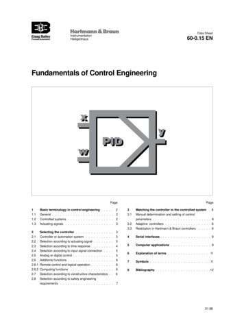
Data SheetInstrumentationHeiligenhaus60-0.15 ENFundamentals of Control EngineeringPagePage11.1Basic terminology in control engineering . . . . . 2General . . . . . . . . . . . . . . . . . . . . . . . . 21.21.3Controlled systems . . . . . . . . . . . . . . . . . .Actuating signals . . . . . . . . . . . . . . . . . . .2322.12.2Selecting the controller . . . . . . . . . . . . . . .Controller or automation system . . . . . . . . . . .Selection according to actuating signal . . . . . . . .3332.32.42.52.62.6.12.6.22.7Selection according to time response . . . . . . .Selection according to input signal connection . .Analog or digital control . . . . . . . . . . . . . .Additional functions . . . . . . . . . . . . . . . .Remote control and logical operation . . . . . . .Computing functions . . . . . . . . . . . . . . .Selection according to constructive characteristics.45566662.8Selection according to safety engineeringrequirements . . . . . . . . . . . . . . . . . . . . .7.33.1Matching the controller to the controlled system . 8Manual determination and setting of control3.23.3parameters . . . . . . . . . . . . . . . . . . . . . . . 8Adaptive controllers . . . . . . . . . . . . . . . . . . 8Realization in Hartmann & Braun controllers . . . . . 94Serial interfaces . . . . . . . . . . . . . . . . . . . . 95Computer applications . . . . . . . . . . . . . . . . 96Explanation of terms . . . . . . . . . . . . . . . . 117Symbols . . . . . . . . . . . . . . . . . . . . . . . 118Bibliography. . . . . . . . . . . . . . . . . . . . 1201.98
Fundamentals of Control EngineeringData Sheet60-0.15 EN1Basic terminology in controlengineering1.1 GeneralThe terms automation, closed-loop control and open-loop controlare frequently used synonymously, although there are considerable differences between them.1.2 Controlled systemsControlled systems are characterized by their time response.There are a number of procedures suitable to determine timeresponse. These are based on the controlled system being activated by a suitable test signal. The reaction of the system providesinformation on its dynamics. A very simple method and thereforecommonly adopted approach is to activate the system through anabrupt change in the actuating signal.Closed-loop control is a subset of automation.Closed-loop tasks are encountered in numerous situations indaily life. The object is to cause the status of a system to approachthat of a predefined value. In control technology [5] this task isdescribed as follows:The step response/transfer function is then evaluated to determine the setting values of the controller.The controlled variable (actual value) x of a controlled systemis measured continuously and fed as a feedback variable r to acomparing element where it is compared to a reference variable(set point) w. A controller output variable YR is calculated fromthe resultant control deviation xw x - w or the error signal e w - x. This output variable YR is then used as a manipulatedvariable y to bring about a reduction in control deviation in thecontrolled system. This yields a closed control loop.Disturbance variables z act on this control loop to repeatedlyelicit a control deviation.The controlled variable x may be replaced by an object variablexA if the variable to be controlled cannot be measured directly fortechnical reasons.When controlling the composition of a mixture it may prove impossible to measure that composition (the object variable) directly.Instead, a representative property (pH, density, turbidity) may beadopted as the controlled variable.Fig. 2ControllerControlled systemZ-15454 ENFig. 1The control loopThe control precision or control quality achievable in thecontrol loop is very dependent on how well the controller ismatched to the particular controlled system. The choice of thecorrect controller and its adaptation to the controlled system aretherefore of primary importance.Open-loop control also acts on a system to change it in thedesired manner. The difference between this and closed-loopcontrol is that the success of the intervention cannot be (directly)monitored. For instance, open-loop control opens a valve withoutchecking whether, and if so, how much water flows through theopened valve. In other words, the output signal of the system(water quantity) is not fed back to the input of the open-loopcontrol.Page 2 of 12Self-regulating controlled system, step response/transferfunctionFig. 2 shows a self-regulating controlled system in which a newsteady-state condition results upon an abrupt change in the inputvariable. This state is reached when the input to the system equalsits output.Controlled systems which are not self-regulating are also ofimportance. These are generally containers in which the fillinglevel is to be controlled.The following data, of importance to the evaluation of the controlledsystem, can be derived from the step response:Controlled system gain: KS x/y1Delay time:TuRecovery time:TgIn process engineering and similar industrial processes, the valueof Tg will vary from a few seconds to several hours.In addition to the absolute value of these variables, the ratio Tu/Tgis also very important.Systems in which Tu/Tg 0.1 are easily controlled. Those in whichTu/Tg 0.3 can still be controlled. If this value is exceeded thenthe results obtained with a controller will deteriorate in inverseproportion to the increase. In such cases the possibility of interrupting the control loop should be investigated so that cascadecontrol can be tested.01.98
Fundamentals of Control EngineeringData Sheet60-0.15 EN1.3 Actuating signals and final controlling elementsActuating signals constitute the input signals of controlled systems. They allow changes in power supply, flow cross-sectionsand the like.Relays, contactors, semiconductor switches or continuously-variable thyristor actuators can all be used to vary the power supplyto electrically-heated systems. Relays and contactors are inexpensive and their performance can be easily checked. A disadvantage, however, is that their mechanical life is limited, possiblyresulting in down-time of plant. By contrast, semiconductor switches and thyristor sets are more expensive, but free of wear.Electrically-driven or pneumatically-driven valves and flaps areusually used for the temperature control of gas or oil-heated plantand for the control of flow rates, pressure and the like.The H&B product range includes electrical actuators (Catalogue68), electropneumatic and intelligent positioners and electropneumatic signal converters TEIP (Catalog 18).2Selecting the controller2.1 Controller or automation systemVery different types of controller are used in industrial processcontrol.Compact controllers are preferred for the control of individualcontrol loops. These are characterised by having all the necessaryfunctions contained in a single case.Fig. 3On/off controlModern digital on/off controllers function internally as continuouscontrollers. However, the continuous actuating signal y is converted into a proportional pulse/pause ratio. The value of Tin/(Tin Tout) is referred to as the control action and corresponds to y.On/off controllers can be used with all slow controlled systems ifthe switching frequency does not have to be too high. If a mechanical life of 107 operating cycles is assumed with 6 switchingoperations per minute, then a contactor will have a life of approx.3 years.If semiconductor switches or thyristor switches are used then themaximal switching frequency will be limited by the processingspeed of the controller. The cycle time for digital compact controllers ranges from 30 to 50 ms. The controller outputs are thus resetapprox. 20 times a second. Therefore, for control purposes theswitching frequency of the circuit-breaker should not exceed10 Hz. Three-position controllers or dual on/off controllersThese controllers have three positions, eg.,"strong" – "weak" – "off" or"heating on" – "off" – "cooling on""Strong" – "weak" – "off"In this sense, controllers constitute the least expensive stage ofprocess automation. They are provided with direct inputs andoutputs for process variables as well as a front panel for operationand monitoring of the process. In addition, controllers fulfil therequirements for use under adverse environmental conditions.Digital controllers with serial interfaces are used for centralizedoperating and monitoring of a few control loops in small andmedium size process plants. These, together with computer aidedprocess visualization units such as the WIZCON, offer the leastexpensive way of entering process automation. Although operation and monitoring are grouped together centrally, the controllersare still independent in function. This ensures a high degree ofsafety and availability for the process.Even if freely programmable control systems with integratedPID controllers are used, in many cases there is still the need tounderlay digital controllers. This is especially the case if the safetyand availability of control loops is the primary consideration or ifthe controlled systems are fast-acting.Automation systems, such as the Contronic P, are generallyused for the automation of large industrial process plants. Theseassume control and other tasks.2.2 Selection according to actuating signalControllers fall into different categories, depending on the type offinal controlling element: On/off controllers for the control of relays, contactors andsolenoid valves. There are only two positions "on (1)" and"off (0)".01.98Fig. 4aThree-position control"Heating on" – "off" – "cooling on"Fig. 4b Three-position controlThe "strong-weak-off" controller is more properly referred to as aon/off controller with a limit signal contact since switching between"strong" and "weak" is achieved through a limit contact which hasno time response. This limit contact is always derived from thecontrol deviation so that irrespective of the set point value whichhas been set, the switching operation will occur, for instance, 10 Cbefore the set point is reached.In three-position controllers for "heating-out-cooling", both controlswitching points have a time response which has to be parameterized separately. The limiting of switching frequency must beborne in mind with three-position controllers too.Page 3 of 12
Fundamentals of Control EngineeringData Sheet60-0.15 EN Step controllers. A step controller is a three-position controllerfor the control of electrical positioning motors with the switchingpositions "clockwise rotation" – "stop" – "counter-clockwiserotation" (open-stop-close).Step controller "Open" – "Stop" – "Close"It can easily be seen that the control oscillation diminishes as theswitching frequency is increased. This is achieved by expandingthe alarm signalling unit to an on/off controller.To improve control performance, it is provided with a structurewhich takes into account not just the instantaneous control deviation but the previous mean time value and the current rate ofchange when calculating the actuating signal.This leads to the PID controller. Its transfer function can bedescribed by the following equation:Fig. 5Step controllerF(S) The limits of application of a step controller are governed by twocriteria:Similarly to an on/off controller, the switching frequency value mustnot be too high because of the mechanical life of the contactor.The actuating time of the positioning motor for the positioningdistance effectively used should be of the order of 60 s and shouldnot drop below approx. 30 s, otherwise control will no longer bestabile. Assuming this operating period for 100 % of the positioningdistance, the motor has to run for 150 ms for a positioning distanceof 0.5%. ON-delays and OFF-delays for relays and contactorsbecome apparent here.Td s11 (1 )XpTn s 1 T1 swhere Xp is the proportional band, Tn is the integral-action component, Td is the derivative-action component and T1 is the timedelay constant of the D-component which is always present. Thisequation also describes the on/off controller sufficiently accuratelyif the cycle duration derived from the switching frequency has asmall value relative to the time constants of the controlled system,so that the control oscillation is no longer manifest in the controlperformance.If Tn or Td 0, then the corresponding part of the transferfunction is rendered inoperative and P-, PI- and PD action isobtained.The position feedback signal y is not normally required for loopcontrol. Position feedback signalling is only necessary if outputlimits which have been set in the controller have to be adhered to.Otherwise in manual operation it provides those responsible forsupervising process plant with information. Continuous controllersContinuous controllers change their output signal continuously (0.20 mA or 4 . 20 mA). They are used for the control of rapid-action electro-pneumatic drives, thyristor controllers and frequencyconverters.Fig. 6Output signal "continuous controller"2.3 Selection according to time responseThe simplest type of controller is an alarm signalling unit which,for instance, switches off the heating of a furnace upon a predefined value being reached. The control performance which canbe achieved with this is in most cases inadequate for industrialplant since a control oscillation remains of amplitude b and cycletime T, upon which the values Tu, Tg and Ks depend.Fig. 8Fig. 7Control result of an alarm signalling unit without timeresponsePage 4 of 12Transfer functionsFig. 8 shows the typical transfer functions of the controller for thisequation if there is an abrupt change in the input signal.01.98
Fundamentals of Control EngineeringData Sheet60-0.15 ENDepending on the application, P-, PD-, PI- and PID-controllersmay be used. Their main properties are described below.2.4 Selection according to input signalconnectionP-controllers and PD-controllers lead without special measuresto a rapid and in most cases o
It can easily be seen that the control oscillation diminishes as the switching frequency is increased. This is achieved by expanding the alarm signalling unit to an on/off controller. To improve control performance, it is provided with a structure F d) Fundamentals of Control Engineering Data Sheet 60-0.15 EN