Transcription
Journal of Mechanical Engineering and MechatronicsISSN: 2527-6212, Vol. 3 No. 1 2018 Pres Univ Press Publication, IndonesiaDESIGN OF AUTOMATIC STAMPING MACHINE FOR DATE AND DASHCODE MARKING USING PNEUMATIC SYSTEM AND PLC CONTROLLERNanang Ali Sutisna1 and Reza Alfarisi Firmansyah2Mechanical Engineering, President UniversityJABABEKA Education Park Jl. Ki Hajar Dewantara, Cikarang Utara, Bekasi 175501email: nanang.ali@presiden.ac.id2email: rezaalfarisi30@gmail.comAbstrakPenelitian ini dimaksudkan untuk merancang mesin otomatis untuk mencap kode tanggal dantanda hubung pada karton induk untuk kemasan blister-pack. Kuantitas proses manual yang adadalam memproduksi master carton tidak sesuai dengan tuntutan, oleh karena itu diperlukan mesinyang meningkatkan proses produksi dengan karakteristik sebagai berikut: cepat, mudah digunakandan dirawat, serta terjangkau untuk mendukung program penghematan biaya. Desainmenggunakan sistem pneumatik dengan pengontrol PLC untuk mengotomatisasi proses.Kata kunci: Proses Pengemasan, Otomasi, Penumatic, PLC ControllerAbstractThe research is meant to design an automatic machine for stamping the date and dash code onthe master carton for the packaging of the blister-pack. The quantity of existing manual process inproducing the master carton does not meet with the demands, therefore, it needs a machine thatimprove the production process with the following characteristic: fast, easy to use and maintain,and also affordable in order to support the cost saving program. The design uses pneumaticsystem with PLC controller to automate the process.Keywords : Packaging Process, Automation, Penumatic, PLC ControllerIntroductionThe ABC company produces many variety of toys such as Fashion Dolls, Match Box, PlayBoard and Die Cast Car Toys with Production Plant around the world. The Indonesian plantproducing Die Cast Car Toy and it have 2 million cars each week in demands. In the process ofassortment of product the company has 2 different packaging, the first packaging named as blistercar pack, the function is to be the container of the DIE-CAST Car Toy and also as the commercialpurpose in marketing the product to the customer. The second packaging is master carton pack, thefunction is to be the container of 12 pack of blister car pack in delivering to the market/customers.Blister car packaging itself could contain until 5 cars for each blister pack carton and it hasautomatic processes by the Auto-Packing machine to reach the target of the demands, Auto-Packingmachine works for divide the cars to each design of blister pack and giving the date code to theblister pack carton. The problem is master carton packaging is still producing by manual processesfor forming the master carton and giving the date and dash code stamping to the master carton.Giving the date and dash code stamping in actual the operators are only able to produce 1372 mastercarton for each shift, meanwhile the demands of the company are 2 million cars each week. In thatcase the company at least need to produce 33.500 master cartons each week or 5600 master cartoneach shift. Because the demand of the master carton is 5600 master cartons per shift. This design isdeveloped to fulfill the program of cost saving and optimizing the process of assortment especially40
Journal of Mechanical Engineering and MechatronicsISSN: 2527-6212, Vol. 3 No. 1 2018 Pres Univ Press Publication, Indonesiain giving the date and dash code for master carton in order to gaining the productivity and also theprofit of the company.TerminologyEngineering DesignABET (Accreditation Board for Engineering and Technology) states that “engineering designis the process of devising a system, component, or process to meet desired needs”. Then in a designit is good also if we include the variety of realistic constraints that will arise such as, safety,economic, aesthetic, etc. Depth of design is also divided into several classes depending on thereasons and how to build a design. The class is divided into 3 levels namely adaptive design,develop design, and new design [1].Pneumatic SystemIn the manufacturing department many utilities are in use such as electricity, natural gas,water, and also air, pneumatic is a system that utilizes the power carried by the air in a tool.Pneumatic system is widely used in Industrial Automation because it is quite simple and reliable,pneumatic is also often used because it quiet cheap technology in comparison with othertechnologies such as hydraulic or electric motor in addition to the unction of moving a very lightload for example it will spend much cost if use in hydraulic or electric motor. Based on the figureabove, Pneumatic is simpler if compared with hydraulic and electric system, give more profit on thecapital cost and maintain [2].Programmable Logic Controller (PLC)Programmable logic controller (PLC) is a special form of microprocessor-based controller thatuses a programmable memory to store instructions and to implement functions such as logic,sequencing, timing, counting and arithmetic in order to control machines and processes [3].PLCs are similar to computers but whereas computers are optimized for calculation anddisplay tasks, PLC are optimized for control tasks and the industrial environment. Since the PLCsare:1. Rugged and designed to withstand vibrations, temperature, humidity and noise.2. Have interfacing for inputs and outputs already inside the controller.3. Are easily programmed and have an easily understood programming language which isprimarily concerned with logic and switching operations.Cycle TimeIn designing the machine using the pneumatic system the first thing should to determine is thepressure supply to lift the load, basically the force of the actuator should be higher than the Load. Itshould be noted that the fluid pressure has no effect to the cylinder speed [4], the speed isdetermined from the Area of the piston and the flow-rate so the total time would be the volume ofthe air consumption at distance that would be reach divided by the flow rate, below is the step tofind cycle time:1. Find the Volume from the air consumption𝑉 𝑄 𝑑Where:𝑉: The volume of air consumption (𝑙)𝑄: The air consumption for each cm (𝑙/𝑐𝑚)41
Journal of Mechanical Engineering and MechatronicsISSN: 2527-6212, Vol. 3 No. 1 2018 Pres Univ Press Publication, Indonesia𝑑: The distance of the stroke moves (𝑐𝑚)2. Find the cycle time𝑡 𝑉𝑣𝑎Where:𝑡: The time (𝑠)𝑉: The volume (𝑙)𝑣𝑎 : The flow rate (𝑙/𝑠)Bending StressTo calculating the construction of machine, it will consider about the stress of the material inwhich shape. Then at this design the critical point will be in the bending stress, the bending moment𝑀 along the length of the beam can be determined from the moment diagram. Below is the formulaof bending stress :𝜎𝑏𝑒𝑛𝑑𝑖𝑛𝑔 𝑀𝑦𝐼where:𝜎𝑏𝑒𝑛𝑑𝑖𝑛𝑔 is bending stress (𝑀𝑃𝑎)𝑀is Moment (𝑁𝑚𝑚)𝑦is distance to neutral axis (𝑚𝑚)𝐼is Area of inertia ( 𝑚𝑚4 )The bending moment at any locations along the beam can be used to calculate the bendingstress over the beam’s cross section at that location. The bending moment varies over the height ofthe cross section according the formula below:𝑀𝑥 𝐹𝑙𝑦where:𝑀𝑥is the Moment along the beam (𝑁𝑚𝑚)𝐹is the Force that distributed to the beam (𝑁)𝐿𝑦is the distance of the force (𝑚𝑚)The Area moment of the inertia is a property of two-dimensional plane shape whichcharacterizes its deflection under loading [5]. To determine the moment are of inertia is depends onthe shape of the area, for the rectangular area will use the formula below𝐼 1𝑏ℎ312where:𝐼is Area of inertia (𝑚𝑚4 )𝑏is breadth (𝑚𝑚)ℎis the height (𝑚𝑚)42
Journal of Mechanical Engineering and MechatronicsISSN: 2527-6212, Vol. 3 No. 1 2018 Pres Univ Press Publication, IndonesiaAllowable Bending Stress𝐴𝑙𝑙𝑜𝑤𝑎𝑏𝑙𝑒 𝜎𝑏𝑒𝑛𝑑𝑖𝑛𝑔 𝑦𝑖𝑒𝑙𝑑 �𝑦 𝑓𝑎𝑐𝑡𝑜𝑟Deflection as a result from bending moment𝐹 (𝐿3 )𝐷𝑒𝑓𝑙𝑒𝑐𝑡𝑖𝑜𝑛 3 𝐸 𝑙Allowable Deflectiona𝑙𝑙𝑜𝑤𝑎𝑏𝑙𝑒 𝑑𝑒𝑓𝑙𝑒𝑐𝑡𝑖𝑜𝑛 𝑐𝑜𝑒𝑓𝑓𝑖𝑐𝑖𝑒𝑛𝑡 𝑑𝑒𝑓𝑙𝑒𝑐𝑡𝑖𝑜𝑛 𝐿𝑒𝑛𝑔𝑡ℎComparison between the deflection and allowable deflection, the allowable deflection must begreater than the deflection.𝑎𝑙𝑙𝑜𝑤𝑎𝑏𝑙𝑒 𝑑𝑒𝑓𝑙𝑒𝑐𝑡 𝑑𝑒𝑓𝑙𝑒𝑐𝑡𝑖𝑜nBreak Even PointBreak-even point is to give an answer to the business such as “how much sales be decreasedand the company still continues to be profitable”. Break-even analysis is extremely important beforestarting a new product or new decision in investing a tools or machine. Break-even analysis basedon categorizing production costs between those which are variable and those which are fixed [6].Below is the formula to calculate the break-even point𝐹𝐶𝐵𝐸𝑃 𝐶𝑆 𝑉𝐶Where: 𝐵𝐸𝑃 is Break-even point 𝐹𝐶 is Fix cost 𝐶𝑆 is the profit 𝑉𝐶 is the variable costMethodology1.Requirement StudyThe requirements will be very important on analysis that will be performed. Tabel 1 below arethe requirements of the company:Table 1. RequirementNoDescriptionRequirements1Giving date and dash code automaticallyMachine2Production target 5600/shiftFast3Easy to Use and MaintainOperable43
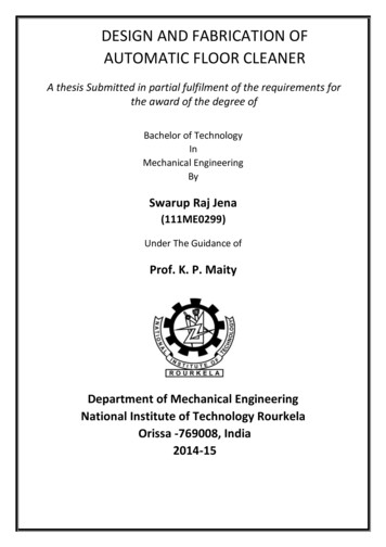
Journal of Mechanical Engineering and MechatronicsISSN: 2527-6212, Vol. 3 No. 1 2018 Pres Univ Press Publication, Indonesia42.Apply the cost saving programAffordableConceptual and Detailed DesignThen in order to meet the requirements, the researcher develop the conceptual design of themachine to become the detailed design using CATIA V5 software to realize the imagination into acomputer aided design (CAD). This design is one of development design from the stampingmachine for brass. The detail of design is shown in figure 1 below:Figure 1. Ideas of designFrom the requirements and idea of design the researchers choose the tools for the movementsystem by using linear actuator, then for the working sequence would be:Table 1 Working sequencesNoType of Work3.ToolsDistance of Movement1MarkingDouble Acting Cylinder250mm from initial position2Un-markingDouble Acting Cylinder250mm from Marking position3StampingDouble Acting Cylinder70mm from initial position4Un-stampingDouble Acting Cylinder70mm from Stamping positionPLC ProgrammingFrom the Data collection the researcher creates the program to run the pneumatic system asthe expected working sequences of the machine. The researcher has decided to using theProgrammable Logic Control (PLC) to controlling the working sequences, the language of themachine is using binary code signal, binary code uses to give the signals to the output memory ofthe PLC. To realize that binary code the researcher using the Function Block Diagram to inputting44
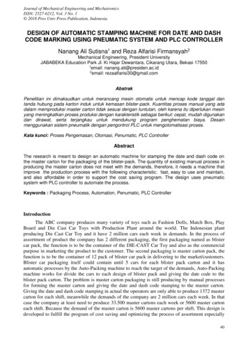
Journal of Mechanical Engineering and MechatronicsISSN: 2527-6212, Vol. 3 No. 1 2018 Pres Univ Press Publication, Indonesiathe program. From those, the researcher will create Block Function methods for choosing the way toinputting the program methods by using FESTO Fluid simulator. The function would be:Figure 1. Program input of PLCTo calculate the cycle time there are some required data that will be need. The data are pressure,flow rate from the valve, area of every sequences. The details of data required will be listed below:Pressure ( P ): 4 barsFlow Rate ( 𝑣𝑎 ): 310 l/min or 5.16 l/sMarker sequence is using Double acting cylinder to carrying the marker batch until 250mmfrom initial position, so the calculation would be shown below:Distance ( s ) 25 cm Mass ( m ) 0.81 kgDiameter of Bore ( d ) 0.032 mArea ( A ) 0.000804 𝑚2From the figure above the researchers know that there is acceleration at this system from thestatic condition into steady. But usually the acceleration has the small value so it will not consider tothis calculation indeed there is acceleration. The calculation when the flow is steady would be:a. Find the Volume from the air consumption𝑉 𝑄 𝑑𝑙𝑉 0.027 25𝑐𝑚𝑐𝑚𝑉 0.675 𝑙45
Journal of Mechanical Engineering and MechatronicsISSN: 2527-6212, Vol. 3 No. 1 2018 Pres Univ Press Publication, Indonesiab. Find the cycle time of movement𝑣𝑎 is the flow of air from the valve, in this calculation the flow would be controlled by thetool called as “flow control” then it would be open the until 30% aperture, as we know fromthe given condition the flow of air Figure 4. 15 Free body diagram and graph of Markingsequence (a) Simple system of marking sequence (b) Graph for P1 is Pin, P2 is Pout, andspeed [4] 59 from the valve is 5.16 l/s so the flow after controlled by flow control with 30%aperture would be 1.16 l/s. then the calculation for the cycle time would be:𝑡 𝑉𝑣𝑎0.675 𝑙5.16𝑙/𝑠 0.30𝑡 0.436 𝑠𝑡 So from the discussion the researcher will calculate the total cycle time from every sequenceand cycle time of the operator to become the total cycle time of process, the total cycle time wouldbe:𝚺𝒕 𝒕𝑴𝒂𝒄𝒉𝒊𝒏𝒆 ��𝒉𝒊𝒏𝒆 𝒕𝑴𝒂𝒓𝒌𝒊𝒏𝒈 𝒕𝑼𝒏𝒎𝒂𝒓𝒌𝒊𝒏𝒈 𝒕𝑺𝒕𝒂𝒎𝒑𝒊𝒏𝒈 𝒕𝑼𝒏𝒔𝒕𝒂𝒎𝒑𝒊𝒏𝒈From the equation of 𝚺𝒕 above the researcher could find cycle time of machine and operator.The cycle time of operator has been simulated by the researcher for loading-unloading then pressthe push button and the result is about 2.5 s, then the table of the total cycle time of machine will beshown in the bale below:Table 2 Cycle time of ingDistance(cm)252577Air consumptionfor full stroke (L)0.6750.4250.1890.119Cycle Time (s)0.4360.2740.1220.076Σ𝑡 3.4 𝑠 4 𝑠𝑒𝑐𝑜𝑛𝑑4. Machine Construction AnalysisFor calculating the construction of machine, the researcher has chosen the most critical partthat happens by force of the stamping-un-stamping actuator. Then to simplify the cases, the freebody diagram would be shown in the figure below:Given:Length 220 mmThickness (b) 10 mmWidth (h) 30 mmF 80.4 NYield strength 215MpaSafety factor 8Coefficient of deflection 0.000546
Journal of Mechanical Engineering and MechatronicsISSN: 2527-6212, Vol. 3 No. 1 2018 Pres Univ Press Publication, IndonesiaFind Bending Stress𝑀𝑥 80.4 220𝑀𝑥 17688 𝑁𝑚𝑚FArea Momen of Inertia1𝐼 (10) (30)3121𝐼 (10) 27000121𝐼 27000012𝐼 225000 𝑚𝑚4Bending stress17688 𝑁𝑚𝑚 15 𝑚𝑚22500𝑚𝑚4 11.792 N/𝑚𝑚4Figure
DESIGN OF AUTOMATIC STAMPING MACHINE FOR DATE AND DASH CODE MARKING USING PNEUMATIC SYSTEM AND PLC CONTROLLER Nanang Ali Sutisna1 and Reza Alfarisi Firmansyah2 Mechanical Engineering, President University JABABEKA Education Park Jl. Ki Hajar Dewantara, Cikarang Utara, Bekasi 17550 1email: nanang.ali@presiden.ac.id 2email: rezaalfarisi30@gmail.com