Transcription
PassPoint ExpressRelease 1.1QUICK START GUIDEFor Access Control KitsTD0082 rev1299
Table of ContentsIntroduction . 3Understanding PassPoint Kits . 3System Hierarchy . 4About Your PassPoint Access Starter Kit. 4Installing PassPoint Hardware . 6Installing PassPoint Software . 11Configuring PassPoint Software . 11Adding Kits . 14Customizing Your System. 16IntroductionThis document contains sections that provide the following: A description of PassPoint Kits The PassPoint system hierarchy A description of the PassPoint Access Starter Kit (ASK) Procedures for the installation of the PassPoint Starter Kit Hardware Procedures for installing PassPoint Software and initial system configuration Procedures for adding kits Procedures for creating reports Procedures for archiving dataUnderstanding PassPoint KitsThis guide is about PassPoint Kits, the basic pre-configured PassPoint packages you will useto quickly get your system up and running. All kits are self-contained. By combining kits(and separate PassPoint modules), you can expand and build on any existing PassPointinstallation.There are four types of PassPoint kits: Access Starter Kit (ASK) — The ASK contains everything you need to get a two-doorinstallation up and running. It is the basic building block of most PassPoint systems.Most of this guide describes the ASK. Basic Starter Kit (BSK) — The BSK contains everything except card readers and cardsthat you need to get a two-door installation up and running. This kit is designed primarilyfor retrofit installations. Most of the material in this document, with the exception ofcards and card readers that you are using, apply to the BSK. Note that the PassPointprogram defaults to ADEMCO cards and proximity readers. If your cards and/or readersare different format or type, you will need to modify your system accordingly. Door Expansion Kit (DEK) — The DEK allows you to add two more doors to an alreadyoperational PassPoint system. The components of the DEK, as well as installation andconfiguration instructions, are provided in the “Adding Modules” section of this document. Card Enrollment Kit (CEK) — The CEK is a kit that allows you to quickly enrollsystem ID cards. It consists mainly of a stand-alone card enrollment reader that connectsdirectly into your existing system. Installation and configuration instructions for the CEKare provided in the “Adding Modules” section of this document.PassPoint Express Quick Start Guide3
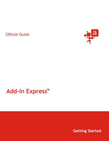
System HierarchyThe PassPoint system is composed of kits. Shown below is an example of a PassPointinstallation:RR1RR1RRRRReae 1ReaeRRRer r eRRRReae 1ReaeRRRReae 1ReaeAbout Your PassPoint Access Starter KitThe PassPoint Access Starter Kit (ASK) has been designed to be the easiest access controlsystem to install and configure. Where possible, default configuration options have beenprovided. If you follow the procedures in this guide, you should have no trouble getting yoursystem operational, even if you have very little experience with access control.What’s inyour kit?Your Access Starter Kit consists of the following hardware components: 1 pre-configured access panel,consisting of the following:1 metal enclosure1 Main Logic Board1 Door Control Module1 Distributed Power Supply Unit 1 plug-in transformer 2 mullion-mount proximity readers(ASK only)4 1 6139 keypad ID cards (ASK only)(for use with card readers) PassPoint Express software 1 RS-232 cable (null-modem cable)(used for connecting your PassPoint panelto your user computer serial port)PassPoint Express Quick Start Guide
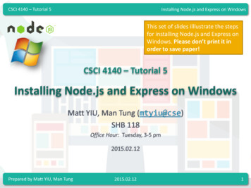
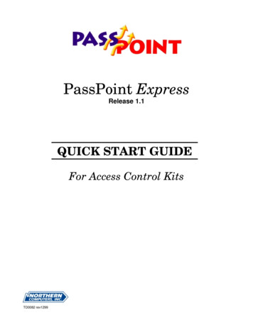
Majorcomponentsr19 eelle22RR1Ra aeree e rleerleeeTDrreeTDrrreer 1reer 2DrDrAccess Starter Kit intypical system configurationThere are four main components to your PassPoint system. They are:Main Logic Board (MLB)The MLB is the central controller of the PassPoint system. It contains the card database, theevent log, and system configuration information. It also keeps track of the system status. TheMLB receives its power from the PassPoint power supply, and communicates with the DoorControl Module (described below) to determine if access should be granted at a particularAccess Point.Door Control Module (DCM)The DCM provides all the inputs and outputs required to manage two Access Points (i.e.,doors). The DCM can connect to two card readers and simultaneously accept card data fromtwo card readers. It provides two Form C, supervised-output (i.e., voltage-monitored) relaysthat are used to operate electromagnetic door locks or door jamb-mounted lock strikes. It alsoprovides two trigger outputs that can be used to operate sounders or LEDs.Distributed Power Supply Unit (DPSU)The DPSU provides all the power needed by the MLB and DCM. It is connected to the ACline voltage via an 18VAC, 50VA plug-in power transformer (supplied with your kit). TheDPSU provides a battery backup/charger connection and supports a 7AmpHour battery (notsupplied).The PassPoint Express system interfacePassPoint Express is a software program that allows the computer to communicate with theMain Logic Board of the system. It is compatible with Windows 95, Windows 98, andWindows NT 4.0. You will be using PassPoint Express to configure the system. After thesystem is up and running, the system operators will be using PassPoint Express to operatePassPoint.PassPoint Express Quick Start Guide5
Installing PassPoint HardwareThis installation procedure is designed to be used for the installation of both Access StarterKits (ASK and BSK) and Door Expansion Kits (DEK), but not individual modules. Forinformation on installing individual system modules, please refer to the PassPoint ExpressInstallation and Setup Guide.Step 1: Mount the EnclosureAll of the Kit enclosures contain pre-mounted modules. When mounting an enclosure, becareful not to damage the modules.Enclosures, which house the system’s modules, must be mounted:1. Inside a secure area in a clean, dry, and vibration free place that is convenient fortechnician access.2. On a sturdy wall with appropriate anchors.3. Near a suitable AC power outlet.In addition, if you will be operating PassPoint Express in the on-line mode, where the systemmodule (MLB) is connected to the system PC all the time, the enclosure containing the MLBmust be within:a. 6 feet of the system’s PC if you plan on using the 6’ RS232 null-modem cable includedin the kit.b. 50 feet of the system’s PC, and you must provide your own RS232 null-modem cable.Note that the enclosure requires a 9-pin “D” connector.c. The distance requirements of the short-haul modems connected between the enclosurecontaining the MLB and the system PC.To mount the enclosure:1. Unlock and remove the door.2. Position the enclosure on the wall. Mark four mounting holes using the holes in the backof the enclosure as a template.3. Drill the holes and, using four anchors or fasteners, mount the enclosure to the wall.3. Reinstall the door.Step 2: Connect ModulesWarning: Do NOT apply power until all wiring connections have been made.The pre-mounted Power Supply (DPSU), MLB, and Door Control (DCM) Modules must bewired together for proper operation.6PassPoint Express Quick Start Guide
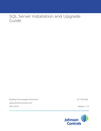
Connecting Power and Ground to the DPSU1. Connect the leads of the powertransformer to terminals 1 and 2 ofthe DPSU. Do not apply power untilall wiring connections have beenmade.2. Connect the DPSU Earth Ground,terminal 3 to the metal enclosure andto a reliable earth ground.D11092882019 1029 28 2222222 211D12811 12 19 10111118 19 20112TTT1 212811 12 19 10111118 19 20TTDTDConnecting the MLB to the DPSU1D11Connect the supplied local power wireharness between DPSU connector J1 andMLB connector J1.092882019 1029 28 2222222 2111118 19 201D12811 12 19 101111289 1011 12 1111118 19 20Connecting the DCM to the DPSUD11Connect the supplied local power wireharness between DPSU connector J5 andDCM connector J1.092882019 1029 28 2222222 211D112811 12 19 10111118 19 20112811 12 19 10111118 19 20Connecting the DCM to the MLBNote: Connect the communicationnetwork wire between the MLB andDCM using twisted-pair wire.1. Connect one lead between terminal 1of the DCM and terminal 16 of theMLB.2. Connect the other lead betweenterminal 2 of the DCM and terminal15 of the MLB.PassPoint Express Quick Start GuideD11092828019 1029 28 21222211118 19 20222 211D12811 12 19 10111289 1011 12 1111118 19 20117
Connecting the MLB Communication ConnectorThe system comes with a 9-pin RS-232ribbon cable used to connect the MLB tothe communication connector located onthe side of the enclosure.1. Connect the header on the RS-232ribbon cable to MLB connector J2,located on the right side of themodule.21D11092882019 1029 28 2222222 21T2DD1D12. Connect the 9-pin “D” connector onthe RS-232 ribbon cable to the rightside of the enclosure using thehardware supplied.2811 12 19 10111118 19 20112811 12 19 10111118 19 20Connecting the Card ReadersNote 1: Readers included with the Kithave nine leads, but only five leads mustbe wired. The remaining four leads (blue,brown, yellow, purple) are not used anddo not have to be connected.11 12 1111118 19 201222222 211DD12811 12 19 101111DT 029 28 2D01T DT 1 D2D89 10D 12D98DT 002DD 12D1T DT 1 DNote 2: When installing a BSK, checkthe voltage requirement of your readers.If your readers use 5VDC instead of 12VDC, connect the DC leads toterminal 15 instead of terminal 16.D2218 19 20112811 12 19 10111118 19 201. Wire the leads from Reader 1 to theterminals of the DCM as shown.2. Wire the leads from Reader 2 to theterminals of the DCM as shown.D1D2Connecting Door Strike or Mag Lock Power to the DCMWire the door strike or mag lock outputon the DPSU terminal #7 to DCM outputrelay common terminal #29 for door Aand terminal #24 for door B.Warning: The door strikes or mag locksused must have a working voltage of12VDC and must not draw more than450mA each.8D811092828019 1029 28 2222222 2129 28 2122D12811 12 19 10111118 19 2011289 1011 12 1111118 19 20PassPoint Express Quick Start Guide
Connecting Door Strikes or Mag Locks to the DCMWire the corresponding door strike to theNormally Open (N.O.) relay, terminal #28for door A and terminal #23 for door B.DT- OR Wire the corresponding mag lock to theNormally Closed (N.C.) relay, terminal#30 for door A and terminal #25 for doorB.Caution: It is absolutely necessary touse an electric suppressor such as aNorthern S-4 to provide transientprotection for magnetic locks/door strikesand relay contacts. Install the suppressoracross the leads connected to the lock asclose as possible to the lock.D029 28 2222222 211109282801TDDT9 1029 28 22222TDDTTD22 21TD1D120811 12 19 10111129 28 2222222 2118 19 2011289 1011 12 1111118 19 20Connecting the Display KeypadPassPoint uses a standard ADEMCO6139 keypad, supplied with the Kit, todisplay system status and annunciatetrouble conditions. Mount the keypad inan area where it can be seen and heard.Only one keypad can be used with thePassPoint system.1. Remove the case back from thekeypad by pushing down on the twosnaps at the top of the case.3. Mount the case back to a wall orcabinet face.4. Splice the wiring from the MLB tothe supplied flying lead connectorand plug the connector into thekeypad PC board.110928280111 12 119 1029 28 2222222 21112811 12 19 10111118 19 20DDTDT TDD 12D2. Route the wiring from the PassPointsystem panel (MLB) through theopening in the case back.D11289 1011 12 1111118 19 20RR1R19 D5. Connect the wires from the keypad tothe terminals of the MLB as shown.6. Re-attach the keypad to its case back.PassPoint Express Quick Start Guide9
Connecting the MLB to System PCThe system PC can be connected directlyto the PassPoint MLB, through an RS232 cable or via short-haul modems; orremotely, using dial-up modems.To direct-connect the MLB to the systemPC:1. Connect the 9-pin “D” connector onthe supplied RS-232 cable to the 9pin “D” connector on the side of thePassPoint enclosure.2. Connect either the 9-pin or 25-pin “D”connector on the other end of thesupplied RS-232 cable to an availableCOM port on the back of the systemPC. Record the COM port for lateruse when programming the software.COM Port D1109828019 1029 28 2222222 211-ORTo connect the MLB to the system PC viamodems:2D12811 12 19 10111118 19 2011289 1011 12 1111118 19 201. Connect the 9-pin “D” connector onyour modem cable to the 9-pin “D”connector on the side of the PassPointenclosure and connect the oppositeend of the cable to your modem.D2. If your computer is not alreadyconnected, connect one end of yourmodem cable to your modem and theremaining end of the modem cable toan available COM port on the back ofthe system PC. Record the COM portfor later use when programming thesoftware.COM Port Step 3: Power Up the PassPoint PanelsWarning: Do not power up the system until all previous steps have been completed.1. Plug in the power transformer for the system panel containing the MLB.2. Within 60 seconds of power-up, press and hold down the [1] and [3] keys simultaneouslyon the 6139 keypad.Pressing these keys puts the keypad into address mode. The current, default keypadaddress of “31” appears on the display.3. Press the [0] key twice to enter the address of “00” and then press the [*] key to save thenew address. Once the proper address of “00” has been entered, the keypad displays thesystem name, and date and time.Do not plug in the power transformer for any remaining panels until you are ready tocomplete the module enrollment process.10PassPoint Express Quick Start Guide
Installing PassPoint SoftwareNote: It is strongly recommended that you exit all Windows programs before running Setup.To install PassPoint Express:1. Insert the PassPoint Express software CD-ROM into your CD-ROM drive.2. If the PassPoint CD Launch utility does not automatically start, click the Start button,then click on Run. In the dialog box that appears, type: d:\CDLaunch (where “d” is thedrive letter for your CD-ROM drive) and click the OK button, or press the [Enter] key.3. From the CD Launch utility window, click the Install PassPoint button to begin thePassPoint software installation.The PassPoint installation program will guide you through the installation process,prompting you for the necessary information. Each time you complete a step, click Next toadvance to the next step.Once the software installation process is complete, the PassPoint Express iconwill automatically appear on your desktop and in the Start menu.Configuring PassPoint SoftwareStep 1: Start PassPoint ExpressThere are two ways to start PassPoint Expresssoftware:1. Double-click on the PassPoint ExpressShortcut.OR2. From the Start Menu,click on the Startbutton, click on Programs, highlightPassPoint Express, click on PassPointExpress.PassPoint Express now starts.The Login screen will be displayed, prompting you for a Usernameand Password.Enter the default Username (installer) and default Password(installer) and click OK to continue.PassPoint Express Quick Start Guide11
Step 2: Create a New AccountThe first time you start PassPoint Express, the system displays the new account screen. Inorder to continue configuring the system, a new account must be created. Accounts allow themanaging of multiple MLB’s. PassPoint assigns one MLB to each account. If you managemultiple sites, each with its own MLB, then each site must be a unique account.To create a new account, enter the following:1. Account Name – The name of the account for thisMLB. Use a descriptive name for this site or EndUser.2. Account Number – The account number associatedwith the MLB. Use any number between 0001 andFFFF.3. MLB # – The number of the MLB in this account.Use the default value of ‘1’.4. Host ID # – The number of the Host ID for thisaccount. The default value equates to ignoring theHost ID, which can be used as is or changed ifdesired.5. Port # – The PC’s COM Port number that is connected to the MLB. Usually between 1and 4.6. Modem? – Select Yes if you are using a modem and then enter a phone number for theremote MLB site. Use the default value “No” if you are not using a modem.7. Click OK to enter the information and create the new account.Step 3: Default/Enroll/Download ModulesThe Setup Wizard – New Account Creation screen is displayed after clicking OK on the NewAccount screen.1. Setup Wizard, Step 1: Click Next.2. Setup Wizard, Step 2: Click the radio button to select the appropriate setup option. Thefirst, fullest option is recommended. Click Next to continue.3. Setup Wizard, Step 3: Click on the arrow of the drop-down list and click on theappropriate configuration template. Click Next to continue.4. Setup Wizard, Step 4: Click Finish.After configuring the system, PassPoint needs to establish communications with the MLB.Notes: If power was removed from the MLB, power up the MLB panel and wait for thekeypad to display the message “LOCAL ONLINE.”If you are using a modem at the panel, press and release [*] and [#] keys on thekeypad attached to the panel and then wait for the keypad to display the message“REMOTE OFFLINE.”12PassPoint Express Quick Start Guide
The Connect to MLB dialog box appears immediately after running the Setup Wizard (bydefault).5. Click Connect. After a short time, theconnected field changes from FALSE toTRUE, indicating the PC has established aconnection to the system’s MLB, and theSetting MLB Defaults dialog box appears.6. Select the default values desired in thedialog box and click Set Defaults.7. The Confirm dialog box appears. Click Yes.The system defaults are downloaded to the MLB.The system prompts you to enroll the modules. The Auto Enroll dialog box now appearson the screen.8. If you have a printer, click Print Log to create a “walk list” of all modules to be enrolled.9. Click Start Scan. The system searches for connected modules. In order for the system toproperly enroll each module, you must power up the modules in the order listed on theprintout after clicking the Start Scan button. After all modules have been enrolled, theDownload to Account dialog box appears.10. Click Start to download the MLB. Whenthe download is complete, the Add Cardsdialog box appears.PassPoint Express Quick Start Guide13
Step 4: Add Access Cards1. After downloading the MLB, the Add Cards dialogbox appears. Click Yes. The Add Card Wizardstarts.2. Follow the screen instructions for adding at least one card to the system. While addingthe card, assign the card to Access Group 1 when the question is asked. This provides thecardholder with access, through the doors controlled by PassPoint, on workdays (Mondaythrough Friday) from 8:00 AM to 5:00 PM. When you finish with the Add Card Wizard,the following dialog box is displayed.3. Click OK.4. Swipe an enrolled card past each card reader. The event log should show that access hasbeen granted. This provides a test that the system is working properly.The preceding Wizards facilitate configuring the PassPoint system to have two access pointswithout RTE’s or DSM’s. Additionally, enrolled cards use the default work-week sche
MLB receives its power from the PassPoint power supply, and communicates with the Door Control Module (described below) to determine if access should be granted at a particular Access Point. Door Control Module (DCM) The DCM provides all the inputs and outputs required to