Transcription
Calculating Locational TolerancesHoward Gibson CET2021/03/27Contents1 Introduction11.1Objective . . . . . . . . . . . . . . . . . . . . . . . . . . . . . . . . . . . . . . . . . .11.2Copyright . . . . . . . . . . . . . . . . . . . . . . . . . . . . . . . . . . . . . . . . . .11.3Change History . . . . . . . . . . . . . . . . . . . . . . . . . . . . . . . . . . . . . . .12 Modelling22.1Bolts . . . . . . . . . . . . . . . . . . . . . . . . . . . . . . . . . . . . . . . . . . . . .22.2Screws . . . . . . . . . . . . . . . . . . . . . . . . . . . . . . . . . . . . . . . . . . . .32.3Positional Error . . . . . . . . . . . . . . . . . . . . . . . . . . . . . . . . . . . . . . .43 Fastener Configurations90 43.1ImpliedAngles (Warning, Warning, Warning!) . . . . . . . . . . . . . . . . . . .43.2Only Two Fasteners . . . . . . . . . . . . . . . . . . . . . . . . . . . . . . . . . . . .63.3Four Fastener Pattern . . . . . . . . . . . . . . . . . . . . . . . . . . . . . . . . . . .73.4Datum Dimensioning . . . . . . . . . . . . . . . . . . . . . . . . . . . . . . . . . . . .83.5Pitch Circles . . . . . . . . . . . . . . . . . . . . . . . . . . . . . . . . . . . . . . . .93.5.1Diametral . . . . . . . . . . . . . . . . . . . . . . . . . . . . . . . . . . . . . .93.5.2Radial . . . . . . . . . . . . . . . . . . . . . . . . . . . . . . . . . . . . . . . . 11i
4 GD&T Positional Tolerances134.1Positional Tolerances Using the Bolt and Screw Models . . . . . . . . . . . . . . . . 134.2Positional Tolerances from First Principles . . . . . . . . . . . . . . . . . . . . . . . . 144.34.2.1Bolt from First Principles . . . . . . . . . . . . . . . . . . . . . . . . . . . . . 154.2.2Screw From First Principles . . . . . . . . . . . . . . . . . . . . . . . . . . . . 154.2.3Checking Zero Positional Tolerances . . . . . . . . . . . . . . . . . . . . . . . 17Calculations from ASME Y14.5M-1994 Appendix B . . . . . . . . . . . . . . . . . . 174.3.1ASME Y14.5M-1994 Appendix B Example . . . . . . . . . . . . . . . . . . . 185 Example196 Closing Remarks19A Older GD&T Notes20A.1 Positional Tolerances with Zero Positional Error . . . . . . . . . . . . . . . . . . . . 20A.1.1 Positional Tolerances for Bolts with Zero Positional Error . . . . . . . . . . . 21A.1.2 Positional Tolerances for Screws with Zero Positional Error . . . . . . . . . . 22B A more elaborate pitch circle model25ii
List of Figures1Bolted Connection – worst case . . . . . . . . . . . . . . . . . . . . . . . . . . . . . .32Screwed Connection – worst case . . . . . . . . . . . . . . . . . . . . . . . . . . . . .33Datum Pattern . . . . . . . . . . . . . . . . . . . . . . . . . . . . . . . . . . . . . . .54Attachment with two bolts . . . . . . . . . . . . . . . . . . . . . . . . . . . . . . . .65Attachment with Four Bolts in a Rectangle . . . . . . . . . . . . . . . . . . . . . . .76Bolts located from a Datum . . . . . . . . . . . . . . . . . . . . . . . . . . . . . . . .87Pitch Circle Diameter . . . . . . . . . . . . . . . . . . . . . . . . . . . . . . . . . . . 108Pitch Circle Radius . . . . . . . . . . . . . . . . . . . . . . . . . . . . . . . . . . . . . 129Bolt Located by a Positional Tolerance . . . . . . . . . . . . . . . . . . . . . . . . . . 1410Bolted Connection with maximum position error . . . . . . . . . . . . . . . . . . . . 1411Specification of Figure 10 ’s Geometry . . . . . . . . . . . . . . . . . . . . . . . . . . 1512Screwed Connection with maximum position error . . . . . . . . . . . . . . . . . . . 1613Tapped hole and clearance hole with positional tolerances . . . . . . . . . . . . . . . 1614A Screw Through a Plate . . . . . . . . . . . . . . . . . . . . . . . . . . . . . . . . . 2215Minimum sized clearance hole at exact nominal . . . . . . . . . . . . . . . . . . . . . 2316Minimum sized clearance hole with tolerances . . . . . . . . . . . . . . . . . . . . . . 23iii
iv
111.1IntroductionObjectiveLocation tolerances are required to ensure that parts, and their fasteners, fit together and thatfeatures are located to within specification. What follows is a systematic procedure for determininglocational tolerances for bolts, screws, pins, shafts, and features embedded on the parts. Thisdocument is intended as a guide for designers, drafters and drawing checkers.The terminology used in this document will be familiar to anyone who has read up on or is trainedin Geometric Dimensioning and Tolerancing (GD&T).1.2CopyrightThis document is copyright 2021/03/27 by Howard Gibson. You may copy this document ontobulletin boards, web pages and other computer media, as long as the file is unaltered, and thedistribution is not-for-profit. All other rights are reserved.1.3Change History1998 Sep 14: First issue.1998 Dec 01: Clarified some text. Expanded Positional Tolerances section a bit.1999 Aug 24: Added a web page reference. Typo correction.2000 Jul 20: Cleaned up the HTML formatting a bit. No change in text.2000 Aug 27: Clean up HTML some more, finally getting background colour to work. Maximumerror for datum dimensioning as 45 opposite to each other. The section of precise geometrictolerancing made a little clearer.2005 Jul 20: Rewrote GD&T section.2006 Apr 29: Reformatted LATEX code. No change to content.2007 Oct 31: Deleted section Zero Tolerance Applied Without MMC2010 Jun 01: Added Implied 90 subsection. Moved the zero positional tolerance section to theAppendix, and wrote the Positional Tolerance from First Principles section.2010 Jun 02: A couple of minor corrections.2014 Jul 04: Corrected Figure 52015 Jan 02: Corrected Figure 6 and Figure 7 Finally ran spellcheck. Only two corrections! :)
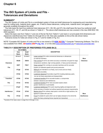
22MODELLING2016 Apr 23: Fixed four bolt pattern equation. Clarified equations for Datum Dimensioning.Added a figure for Datum Patterns.2020 Mar 11: In ASME Y14.5M-1994 Appendix B notes, I swapped H and F into the correctpositions. I updated LATEX code a bit. I clarified my notes on pitch circles. Thank you John Olsonand Edward Alexander.2020 Mar 19: Added separate section on pitch circle radii. Changed MMC to MMB as per ASMEY14.5-2009. Moved elaborate pitch circle model to appendix.2020 Apr 27: Tidied up and clarified Figure 11. Clarified Screw From First Principles a bit.2021 Mar 27: Fixed typos under radial pitch circles. Fixed some issues due to LATEX updates.2ModellingWhen parts are held together by more than one fastener, the tolerances for the holes must ensurenot only that the parts are located to within specification, but also that all the fasteners can beinstalled. Analysis will consist of determining the maximum possible location error that will allowthis, and then working out the equivalent drawing tolerance. It will be assumed that all holesare drilled, punched, tapped or whatever, prior to assembly. If the tolerances generated by thefollowing calculations are not reasonable, drilling at assembly may be the only solution.The analysis will cover a series of fastener configurations and dimensioning procedures. For thepurposes of building analysis models, fastener assemblies can be split up into two categories, whichwill be termed here “bolts” and “screws.” For each of these, we can determine a maximum acceptable error, and for each design configuration, and for each style of tolerance application on thedrawing, we can work out the tolerance.2.1BoltsFasteners pass through clearance holes in both parts. The obvious example of this is a nut and boltassembly, but this could also be a cotter pin assembly or a pre-drilled rivet assembly. The boltscould be clamping more than two parts at a time.See Figure 1 . It will be assumed for analysis purposes, that bolts are located precisely at theirnominal position.1 The two clearance holes are shifted off the nominal position such that theiredges just touch the bolt on opposite sides. This is the maximum acceptable error condition. Ifthe clearance in each hole at MMB is C, then. . .Maximum allowable shift of holes for bolting: B 1C2This is not the only analysis model. See Section 4.3.1 for an alternate model.(1)
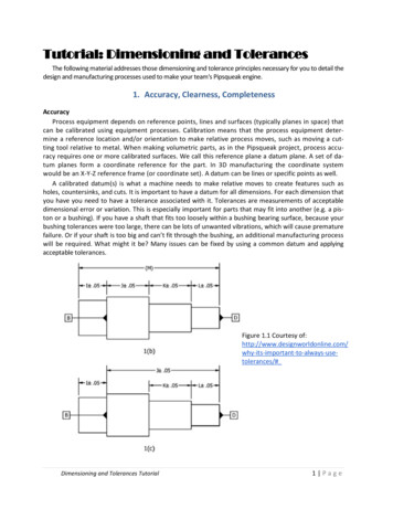
2.2Screws3C2DHOLEDHOLENominal PositionDBOLTCC2Figure 1: Bolted Connection – worst caseC4DHOLENominal PositionDSCREWCFigure 2: Screwed Connection – worst case2.2ScrewsFasteners pass through a clearance hole in one part, and are solidly located in the other part. Thesecould be screws in tapped holes. They could be dowel pins, or they could be features integral toone of the parts. As with a bolted assembly, a screw could be holding more than one piece to itsbase.See Figure 2 . The screw and clearance hole have moved in opposite directions, such that thescrew is touching the edge of the hole. If C is the clearance in each hole at MMB, then. . .Maximum allowable shift of holes for screwing: S C4(2)
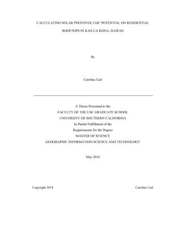
43FASTENER CONFIGURATIONSA screw assembly allows only half the error of a bolted assembly. This is something to consider ifthe location tolerances are difficult to maintain.2.3Positional ErrorThe ASME Y14.5 standard recommends the use of positional tolerances for locating features ofsize, with a secondary preference for profile tolerances. Much of this article looks at tolerancesfor locating holes. This was the original purpose of the article. People still use this notation fortolerances, and it is defined under the ASME standard, so as design checker, you can accept it if itworks. If you are designing or drafting, you will see from this article that positional tolerances arethe better way.For two dimensional configurations, it will usually be assumed that the maximum error occurs at a45 angle. The assumption is that the fabricator’s capability is equal in both the x and y directions.If this assumption is not true for a given application, then the angle, and the resultant calculationsand tolerances can be fudged a bit, although not very much.3Fastener ConfigurationsThe tolerance that must be applied on a drawing feature depends on the configuration of thefasteners and on the dimensioning procedure. Most articles on ASME Y14.5 Dimensioning andTolerancing point out that GD&T provides a maximum of allowance for a given part. This isimportant if the tolerance to be achieved is marginally within the fabricator’s capability., Anincrease in allowance May reduce costs. If tolerances are fairly easy, then the cost of preparing andreading the drawings must be considered. Regardless of how the tolerances are applied, GD&Tprovides a precise interpretation of how the tolerances are to be determined from the dimensions.3.1Implied 90 Angles (Warning, Warning, Warning!)See Figure 3 . ASME Y14.5-2009 paragraph 2.1.1.32 states that undimensioned angles that appearto be 90 are to be assumed to be 90 . The tolerance of an undimensioned orthogonal feature isthe value specified on your default tolerance notes. On most drawings, this is something like 0.5 ,or 1 .3If holes are located from an edge with tolerances, consider the possibility that the edge is notperpendicular to the base. Do you measure from the straight line that contacts the two outsidepointsof the edge? Do you measure from the nearest part of the edge?23On ASME Y14.5M-1994 this is paragraph 2.1.1.2. I don’t know about the ISO GD&T standard.Rule #1 makes this problem less horrible.
3.1Implied 90 Angles (Warning, Warning, Warning!)52.001.625.3753.002.625.3754X.250 THRUUNLESS OTHERWISE SPECIFIED, ALLDIMENSIONS ARE IN INCHES.DIMENSIONS AND TOLERANCES ARE ASPER ASME Y14.5M 2009.0.00 / 0.050.000 / 0.005ANGLES: / 1Figure 3: Datum PatternHOW DO YOU INSPECTTHIS?
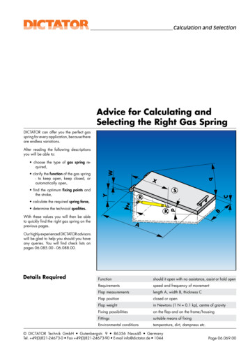
63FASTENER CONFIGURATIONSC2DIM tDIM tFigure 4: Attachment with two boltsThis is not an issue with GD&T positional tolerances, since everything is located from the orthogonal datums you specified. Using a profile tolerance to control the outline of your part is goodpractice.If you are checking drawings prepared with tolerances, you will have to decide how willing youare to argue with the drafter or designer. A machine or sheet metal shop that wants repeat businessis not going to deliver parts 1 out of perpendicular, even if the drawing allows it.3.2Only Two FastenersParts are assembled with two fasteners. It is assumed that the parts are not located accurately toeach other. On the drawings, the holes are dimensioned from each other, rather from a datum.In Figure 4 , the maximum error occurs at both holes, so that tolerance is double the error. . .tb 2 B 2 C2Tolerances for dimensions between two boltstb CFor screws. . .ts 2 S 2 (3)C4Tolerances for dimensions between two screws:ts C2(4)
3.3Four Fastener Pattern7CC2VERT tVERT tHORIZ tHORIZ tFigure 5: Attachment with Four Bolts in a Rectangle3.3Four Fastener PatternParts are assembled with four fasteners. Again, the relative location of the clamped parts is notcritical. On the drawing, the holes are dimensioned with respect to each other as shown in Figure 5.The holes in Figure 5 are shown shifted the maximum distance, at a 45 angle. Again, the erroroccurs at each hole. BC/2 tb 2 2 2 C 1sin 45 2The tolerance for dimensions between four bolts:tb 1.414C(5)For screws. . . SC/4ts 2 2 1 sin 45 2 2 C2
83FASTENER CONFIGURATIONSCVERT tVERT tHORIZ tHORIZ tFigure 6: Bolts located from a DatumThe tolerance for dimensions between four screws:ts 3.4C1.414(6)Datum DimensioningParts are assembled with any number of fasteners. On the fabrication drawings, all the holes aredimensioned from arbitrarily selected X and Y datums.4 For one-off parts, this is popular withmachine shops (and therefore cheaper) because only one set-up is required to locate all the holes. Ifthe two parts are to be located accurately, all the holes must be registered to some locating features.On any non-rectangular hole pattern with more than two holes, the dimensioning effectively isdatum, even if everything is referenced from one of the holes.The model assumes that two holes are located from datums. Each hole can shift in two dimensions,e
2021 Mar 27: Fixed typos under radial pitch circles. Fixed some issues due to LATEX updates. 2 Modelling When parts are held together by more than one fastener, the tolerances for the holes must ensure not only that the parts are located to within speci cation, but also that all the fasteners can be installed. Analysis will consist of determining the maximum possible location error that will allowFile Size: 330KBPage Count: 29