Transcription
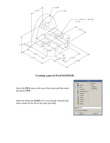
Creating a part in Pro/ENGINEER:Select the FILE menu at the top of the screen and then selectthe option NEWSelect the button for PART (if it is not already selected) andenter a name for the file in the space provided.
This will create a set of three mutuallyorthogonal datum planes and display them onthe screen. They are labeled RIGHT, TOP,and FRONTA few comments on Datum Planes;Datum planes are 2-sided. They have aYellow side and a Red side. The yellow sideis considered primary, that is, in mostcommands involving orientation of the datumplane in 3D space, the facing of the yellowside takes precedence.To create your first shape feature:From the Feature menu select CREATEFor Feature Type select SOLID and in the SolidType menu, select PROTRUSION(a protrusion is a solid feature which adds material to the model)For SolidOptions select EXTRUDE, SOLID and DONEThis specifies that we will be creating our protrusion using the operation of extrusion,which sweeps a planar profile through a distance normal to the plane of the profile.The FeatureControl dialogue box will now open and show what isrequired to create the feature in question. The box lists theproperties for the feature and notes whether they have beendefined, are currently being defined, or are still required.For Attributes select One Side and Done(this option specifies that we will extrude to one side of the planeof the profile; the two side option makes the profile plane themidplane of the feature)The next step is to define a sketch plane. This is the plane on which the extrusion profilewill be sketched. We will use one of the three Datum Planes already created.In the Get Select window choose Query Select and select TOP (you can pick anywhereon its border or on the label). The datum plane will be highlighted. Press the middlemouse button to confirm your selection.An arrow will be displayed showing the direction for feature construction. This is thedirection that the profile will be extruded. You may flip the direction if desired. Select
OK to continue.The next step is to select a horizontal or vertical reference for the sketch plane. Whensketching the profile we will be viewing the sketch plane (in our case, TOP) along a lineof sight normal to that plane. However, we must orient the sketch plane as to whichdirection within the plane is horizontal and which is vertical. Perhaps the easiest way tothink of this is as follows. We will be sketching on the "yellow side" of TOP and henceviewing that side. When we view the "yellow side" of TOP the "yellow side" of one ofthe other two datum planes (either RIGHT or FRONT) will face the top, bottom, leftside or right side of the screen.Select Right from the menu, Query Select, and then choose RIGHT and the MMB toend.The screen display changes and we see the plane view of TOP. We are now in SketcherMode. This where the creation of the shape profile for our first feature will be made.You will notice the grid overlaying the display. This is to assist you in drawing yourprofile.The Sketcher menu is now open. The default selection is Mouse Sketch. When theMouse Sketch option is selected, the mouse buttons function as follows:LMBMMBRMBpick line endpointpick circle center and drag radiuspick tangent arc endpoints*ororcancel circle inputcancel line input* tangent at start point only, first pick must an be existing entityUsing the Mouse Sketch line options (LMB topick, MMB to end), sketch the outline (orprofile) of the part base on TOP. Use theguidelines to help you. While absolute accuracyis not critical, your profile should approximatelycorrect. When completed, your profile shouldappear similar to the one at right.The next step is to provide the necessaryconstraints to restrict our sketched profile torepresent a single shape. In this exercise we willaccomplish this by applying dimensionalconstraints to the profile. These constraints willbe in the form of actual dimensions. The valueassigned to the dimensions is variable and cantherefore be used to alter the profile.
Dimensions can be linear (distance between two parallel line, perpendicular distancebetween a line a point, distance between two points), angular (angle between two nonparallel lines), diametric or radial.For the first profile of our part, we will need onlylinear dimensions. First we will constrain theoverall size of the base. To create the dimensionfor the overall height, first go to the SKETCHERmenu and select Dimension. Next pick the tophorizontal line, then the bottom horizontal line(they will be highlighted) then move the mouse tothe right of the profile and press the MMB. Forthe overall width, pick the two vertical lines andmove the mouse above the profile and pick theMMB. Your profile should look similar to theone at right.Notice that the dimensions do not have values butrather a label will be displayed. We will assignexact values at a later step.Next we will assign values for the inclined edgesof the profile. First the horizontal dimension.While still in the Dimension command, select theleft endpoint of the lower inclined line. Nextselect the right hand vertical line. Finally, movethe mouse to a point below the inclined line andpress the MMB. To create the verticaldimension, select the right endpoint of the sameinclined line, then the lower vertical line, movethe mouse to the right of the inclined line andpress the MMB.If we were careful in sketching the initial profileshape, the software will assume that the samedimensions apply to the inclined feature at thetop. If not, we must repeat the previous processto dimension this shape on the other side.
In Pro/ENGINEER, all features created mustbe located with respect to the existing part. Inour case, the feature we are creating (the shapeof the base), must be located to our part. Sofar, the only features in our part are the 3datum planes, so we must locate our profilewith respect to these. Only a line view of adatum plane may be used for dimensioningpurposes, so we can create a horizontaldimension to RIGHT and a vertical dimensionto FRONT. Pick the left side vertical line ofthe profile and then pick RIGHT (anywherealong its length). Move the mouse above theprofile and press the MMB. Pick the tophorizontal line of the profile and then pickFRONT. Move the mouse to the right of theprofile and press the MMB.We can now apply our dimensional constraints to the profile to ensure that we havesufficient dimensions to fully the profile and produce a single resultant shape. Theprocess is similar to fully dimensioning a geometric shape as you learned in yourengineering graphics class. To apply the constraints, go to the SKETCHER menu andselect Regenerate. If your profile is under-constrained (too few dimensions) you will benotified at this point and will have to rectify the condition before proceeding. If yourhave provided sufficient dimensions, the profile will update in shape and the currentvalues assigned to the dimensions will be displayed.To change the values of your dimensions, go to the SKETCHER menu and selectModify (if not already selected by default). Select the dimension to change by pickingdirectly on the dimension value. Enter the new value at the keyboard and either press theEnter key or pick the Green Check Mark at the right side of the input window tocontinue. Notice that the dimension value will turn white. This indicates that a changehas been made but not evaluated yet. Continue this process until all values have beenmodified to agree with those on the part drawing at the beginning of this tutorial. For thehorizontal and vertical locating dimensions (those to RIGHT and FRONT) use thefollowing value. Set the horizontal dimension to 1.875 and the vertical to 2.125When all dimension values have been updated, select Regenerate to apply the newvalues to the profile shape and see the effect.We are now ready to continue with construction of the feature. Select Done from thebottom of the SKETCHER window. Next go to the VIEW menu at the top of the screenand select Default.
The view will appear as at right. The next step is todefine the distance of the extrusion process. Thearrow shown indicates the direction for the extrusion.The open dialogue lists the options for the extrusion distance. The default isBlind. A blind extrusion is one with a set value for the distance. Select theoption Blind and then Done. Enter the value 1.00 at the keyboard and eitherpress the Enter key or pick the Green Check Mark at the right side of theinput window to continue.We can now proceed with the creation of the extruded feature. In doing sowe will use the FeatureControl dialogue box introduced earlier.We can see from the FeatureControl dialogue listing that all elements for the featurehave been successfully defined. At this point we can preview our geometry to verify thatour construction is correct. Select the option Preview from the FeatureControldialogue.This will generate a preview image of the feature as specified byour current element settings. The preview geometry will appear inred. If we wish to make a change in the feature's specifications, wecan do so now. For example, to change the extrusion Depth, movethe mouse pointer to the listing in the dialogue box for Depth andpick (it will be highlighted). Select the button marked Define andyou will return to the point in feature construction where youoriginally specified depth. You are now able to change the valueand proceed as you did previously.The FeatureControl dialogue will allow to "roll back the clock" toany point in the construction process after you specified the construction technique
(extrusion in our case). You can change whichplane the sketch is on using the Sectionoption, or the direction in which the feature isextruded with the Direction option. Again,you can Preview after any change to verify thegeometry.Once you have the feature's specificationsfinalized, select OK to construct the featureand continue.The next step will be to construct the uprightportion of the part. To do this we will have toattach our sketch plane to the rectangularsurface on the far left of the object as viewed above.The Feature menu will be open. Select the option Create (to create a new feature),FeatureClass Solid, and then from the Solid menu pick Protrusion (again, we areadding material to the part). Our SolidOptions should be Extrude, Solid and Done.We will see the FeatureControl window andwill proceed as we did before, setting thefeature specifications and defining a sketchplane. From the Attibutes menu selectOneSide.Pick surface hereNext we define the sketch plane. SelectQuery Select for the Get Select menu. Movethe mouse to a near the left side of the topsurface (as shown) and pick. The top surfacewill be highlighted but we want the hiddensurface to the left. From the Query Bindialogue pick the other, non-highlightedsurface name. The desired surface should behighlighted. Select Accept to continue.We wish the direction arrow to point to theright as we view the part, so from theDirection menu select Flip and then OK.Next we will orient the sketch plane. From the Sket View menu select Top and thenQuery Select, pick TOP and press the MMB to confirm the selection. This setting
means that as we view the sketch plane theYellow side of TOP will face the top of thedisplay screen.We will now be back in Sketch Mode and ourview should look approximately the same asthat to the right.Since the sketch will be to the top of thecurrent feature, we may wish to Pan ourdisplay. To do this move the mouse pointerto the center of the Sketcher screen, press andhold the CTRL key, then press the RMB anddrag toward the bottom of the screen.Start the sketch by moving the mouse to apoint above the first feature and in line withFRONT. Press the MMB and drag out circle.Press the MMB again to set the diameter. Thesketch shape should appear as shown to theright.Next we will create the lines from the corners of the first feature,which then meet the circle at tangent points. Go to the Sketch menuand select Line. In the Line Type menu select Pnt/Tangent.
Pick the upper left-hand corner of therectangular view of the first feature andthen pick the left side of the circle justcreated. The pick point on the circle doesnot have to be at the point of tangency,anywhere of the left-hand half of thecircle will work. Repeat the process forthe line on the right-hand side. Thesketch should appear as shown below.Next we will need to remove the lower portion of the circle. To dothis we must divide the circle into two segments with the segmentendpoints at the tangent intersections with the lines we just drew.From the Sketcher menu select Geom Tools. From theGeom Tools menu select Intersect. Pick the left-hand line andthen pick the left side of the circle. This will "break" the circle atthe intersection point. Repeat the process using the right-hand line.The circle will now be divided into two arcs and we can delete thelower half. Select Delete from the Sketcher menu and pick thelower half of the circle.Next we will add the dimensionalconstraints to this new profile andmodify the values to agree with ourpart specifications.To dimension the arc, go to theSketcher menu and select Dimension.Pick the arc with the LMB and thenmove to space below and to the left ofthe arc and press the MMB.To apply the vertical locationdimension for the arc, pick the center
point of the arc and then the bottom edge of the first feature (this is the plane of TOP).Move the mouse to the right of the profile and press the MMB.Next we will constrain the center of the arc to lie along the centerline of the part. We willdo this by aligning the center of the arc with FRONT. Go to the Sketcher menu andselect Alignment. Pick the center point of the arc and then FRONT. Your should see aresponse in the message window of "Aligned" and see a dashed line on screen indicatingthe alignment.Next we align the lower endpoints of the tangent lines we drew to lie at the corner of thefirst feature. While still in the Alignment command, pick the lower endpoint of the lefthand line and then pick the upper horizontal line of the first feature. Repeat and align theendpoint of the left-hand line to left-hand vertical edge of the first feature. Again, dashedlines will appear to indicate the alignment. Repeat the process for the right-hand line.Our profile should now be fully constrained. Select Regenerate from the Sketchermenu. Now we modify the dimension values. Select Modify and then pick the value ofthe arc radius. Set the value to 1.25. Select the value of the vertical dimension and setthe value to 2.625. Select Regenerate.Go to the View menu at the top of the screen and select Default.Select Done from the bottom of the Sketcher menu.Arrow will display on screen pointing to one sideof the profile of the other. Note that the promptin the message window says "arrow pointsTOWARD area to be added". This means that thematerial added by the protrusion will be to theindicated side of the profile. For our example thearrow should point inward. Flip, if required andthen pick OK.Next we are prompted for the feature constructiondirection and the distance of the extrusion. Thearrow should point toward the right in our defaultview. Select option Blind and then Done. Enterthe .750 at the keyboard and press the Enter key.Select Preview in the FeatureControl windowand then, if correct select OK.
The next step will be to construct the small feature on the top surface of the base. To dothis we will have to attach our sketch plane to the top surface of the base feature asviewed above.The Feature menu will be open. Select the option Create (to create a new feature),FeatureClass Solid, and then from the Solid menu pick Protrusion (again, we areadding material to the part). Our SolidOptions should be Extrude, Solid and Done.We will see the FeatureControl window and will proceed as we did before, setting thefeature specifications and defining a sketch plane. From the Attibutes menu selectOneSide.Next we define the sketch plane. Select QuerySelect for the Get Select menu. Move the mouseto a near the left side of the top surface of thebase (as shown) and pick. The top surface will behighlighted. Select Accept to continue.We wish the direction arrow to point outward aswe view the part, so select OK.Next we will orient the sketch plane. From theSket View menu select Bottom and then QuerySelect, pick RIGHT and press the MMB toconfirm the selection. This setting means that aswe view the sketch plane the Yellow side ofRIGHT will face the bottom of the display screen.We will now be back in Sketch Mode and our viewshould look approximately the same as that to theright.
The shape of our next feature profile is a rectangle.This can be easily created. From the Sketch Geometry menu selection, Rectangle. Thiscommand allows you to create the four lines of arectangle by defining the diagonally oppositecorners of the rectangle.Create the rectangle such that it is centered overFRONT with its upper edge coincidental with thefront edge of the upright feature and its lower edgecoincidental with the lower edge of the part, asshown in the adjacent view. If you make a mistakein select the starting point, you can start over byreselecting the Rectangle command.To constrain our profile we will need twohorizontal dimensions to specify the width of therectangle and to center it on the part. Vertical sizeand location will be accomplished by aligning therectangle to existing edges of the part.Select Dimension from the Sketcher menu. Pickthe two vertical sides of the rectangle we just drewthen move the mouse to a position below theprofile and press the MMB. Select the left-handvertical line of the rectangle and the line view ofFRONT. Move the mouse to a position above thepart and press the MMB.Select Alignment from the Sketcher menu. Pick the upper line of the rectangle and theobject edge it is draw on top of. Pick the lower line of the rectangle and the bottom objectedge. Again, dashed lines will indicate alignment.Select Regenerate from the Sketcher menu.Now we modify the dimension values. Select Modify and then pick the value rectanglewidth dimension. Set the value to .750. Select the value of the horizontal-locatingdimension and set the value to .375. Select Regenerate.
Go to the View menu at the top of the screen and selectDefault.Select Done from the bottom of the Sketcher menu.Next we are prompted for the feature constructiondirection and the distance of the extrusion. The arrowshould point toward the top of the screen in our defaultview. Select option Blind and then Done. Enter thevalue .250 at the keyboard and press the Enter key.Select Preview in the FeatureControl window andthen, if correct select OK.We will next create the single hole through the upright feature. Pro/ENGINEERprovides a special feature type for the construction of holes. The hole featurewill be located coaxial to the axis of the radius in the upright feature. Since noaxis is displayed, we must first create one.In the Part menu select FEATUREIn the Feature menu select CREATEFor FeatureType select DATUM and for Datum Option select AxisIn the Datum Axis window select Thru Cyl and then in the Get Select menu pickQuery Select. Pick the curve surface at the top of the object and then press theMMB to confirm the selection. An axis should be created and labeled A 1.Now we will create the hole coaxial with axis A 1.
In the Feature menu select Create. For FeatureTypeselect Hole. You are now in the hole feature constructionsequence and the HoleConstruction dialogue box isopen.In the top section of the Hole dialogue box, selectStraight. This option creates a straight walled hole,such as a drilled or bored hole.Next, we must enter the hole diameter. Pick theDiameter input window in the Hole dialogue and enter.75 at the keyboard. Press the Enter key.Next option is for the termination of the hole. Thisparticular hole
In Pro/ENGINEER, all features created must be located with respect to the existing part. In our case, the feature we are creating (the shape of the base), must be located to our part. So far, the only features in our part are the 3 datum planes, so we must locate