Transcription
kell c08.qxd6/29/002:41 PMPage 281C H A P T E R8CREATING A PRO/ENGINEER DRAWINGINTRODUCTIONDrawing mode is used to produce detailed engineer drawings of parts and assemblies. Drawing mode has the capability to produce orthographic views to include section views andauxiliary views. This chapter introduces the fundamentals behind drawing mode and how toproduce an annotated multiview drawing. Upon finishing this chapter, you will be able to Create orthographic views of an existing model within Drawing model.Setup, retrieve, and create sheet formats.Manipulate the settings of a drawing by changing Drawing Setup file options.Create a detailed view of a model.Apply parametric and nonparametric dimensions to a drawing.Show and erase entities such as geometric tolerances, centerlines, and datums.Create notes on a drawing, including notes with leaders and balloon notes.Create a table on a drawing.DEFINITIONSAssociative dimension A parametric dimension that is available for viewing and/or modificationin multiple modules of Pro/ENGINEER.Drawing setup file A text file used to establish many of drawing mode’s default settings. As anexample, the default text height for a drawing is set in the drawing setup file.Format A Pro/ENGINEER module used to create drawing borders and title blocks. Formats canbe added to a Pro/ENGINEER drawing.Multiview drawing The use of multiple orthographic views to display and communicate anengineering design graphically.Nonparametric dimension A dimension created in drawing mode that is not used to construct apart or assembly. Nonparametric dimension values cannot be modified.Parametric dimension A dimension that is used to define a part or assembly feature. Parametricdimensions can be modified or redefined.DRAWING FUNDAMENTALSPro/ENGINEER is a fully integrated and associative engineer design package. Being an integrated package, an array of design, engineering, and manufacturing tools is available.281
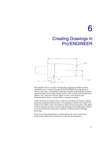
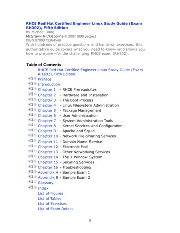
kell c08.qxd6/29/002:41 PM282Figure 8–1Page 282Drawing Setup FileA Pro/ENGINEER drawingComponents of a design can be modeled within part mode, grouped in assembly mode,simulated and tested in Pro/MECHANICA, and machining code developed in manufacturing mode (Pro/NC). The two-directional associativity that exists between modes allowschanges made in one mode to be reflected in another. Combined within a strong computernetwork system, a true paperless manufacturing environment can be established.Two-dimensional orthographic drawings were once considered one of the initial stepsof the design process. A traditional approach to engineering design might require engineering drawings to be produced first, followed by engineering analysis and ComputerNumerical Control (CNC) code production. With Pro/ENGINEER, engineering drawingsare considered “downstream” applications that occur after part modeling and analysis.Pro/ENGINEER’s basic package provides a module for creating orthographic drawings (see Figure 8–1). Within drawing mode, detailed multiview drawings can be createdfrom existing models. Dimensions used to create a part (referred to as parametric dimensions) can be revealed in drawing mode to document a design. Parametric dimension values can be modified in drawing mode with the changes reflected in other modules ofPro/ENGINEER. Options are available for creating section views, detailed views, andauxiliary views. There are options for creating notes, leaders, nonparametric dimensions,and tables. Additionally, within drawing mode is a variety of two-dimension draftingtools.Drawing mode can be used to create detailed drawings from existing parts and assemblies. When creating a new drawing, Pro/ENGINEER provides an option for selecting themodel from which to create the drawing. Also, additional models can be added to a drawing from within drawing mode. Multiple views of a model can be added to a drawing andannotations applied. Pro/ENGINEER provides existing sheet formats (i.e., A, B, C, and D)with detailed title blocks and borders. Format mode can be used to create additional sheetformats.DRAWING SETUP FILEDrawing mode uses drawing setup files (DTL) to control the appearance of drawings.Pro/ENGINEER comes with default settings for a variety of drawing parameter options.
kell c08.qxd6/29/002:41 PMPage 283CHAPTER 8Table 8–1 Creating a Pro/ENGINEER DrawingCommon drawing setup file optionsOption/DescriptionDefault Value (Optional Value)crossec arrow lengthControls the length of cutting-plane line arrowheads.crossec arrow widthControls the width of cutting-plane line arrowheads.dim leader lengthControls the length of a dimension line when the dimensionline arrowheads fall outside of the extension lines.draw arrow lengthSets the length of dimension arrowheads.draw arrow styleSets the arrowhead style.draw arrow widthSets the width of dimension arrowheads.drawing text heightSets the height of text in a drawing.drawing unitsSets units for a drawing.gtol datumsSets the display of geometric tolerance datum symbols.leader elbow lengthSets the length of a leader’s elbow.radial pattern axis circleControls the display of rotational pattern features. Set toyes to produce a bolt-circle centerline.text orientationSets the orientation of dimension text.text width factorSets the width factor for text.tol displaySets the display of tolerance values.0.1875.062500.50000.1875closed(open or filled)0.06250.15625inch(foot, mm, cm, or m)std ansi(std iso, std jis, or std ansi mm)0.2500no(yes)horizontal(parallel or parallel diam horiz)0.8000(.25 through 8)no(yes)Examples of parameters include text height, arrowhead size, arrowhead style, tolerancedisplay, and drawing units. Default values can be changed permanently or set for individual drawings. Multiple drawing setup files can be created and stored for later use. Drawingsetup files have the file extension *.dtl.ADVANCED DRAW SETUP MODIFY VALNew DTL files are created with the Advanced Set Up Draw Setup Createoption. The configuration file option drawing setup file can be used to establish a specific DTL file. If this option is not set, Pro/ENGINEER uses the default DTL file. Tochange the DTL file, select the Draw Setup Retrieve option from the DTL Setupmenu. The configuration file option pro dtl setup dir can be used to set the directorythat Pro/ENGINEER searches for DTL files. The Draw Setup Modify Val option isused to change an individual drawing’s DTL values. To change the values permanently,use the Draw Setup Save option.Table 8–1 provides a list of common DTL file options with default values.SHEET FORMATSA format is an overlay for a Pro/ENGINEER drawing. It can include a border, title block,notes, tables, and graphics. A sheet format has the file extension *.frm. Pro/ENGINEERprovides a variety of predefined standard formats for use with ANSI and ISO sheet sizes283
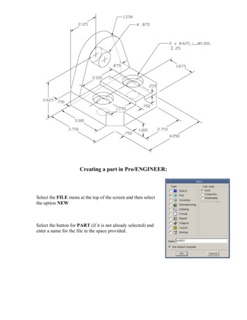
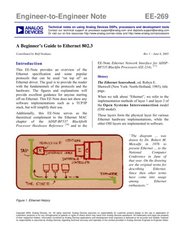
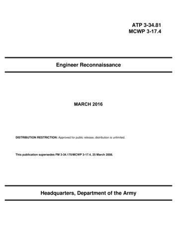
kell c08.qxd6/29/002842:41 PMPage 284Sheet Formats(i.e., A, B, C, and D size sheets). These standard formats can be modified to produce a customized format. Additionally, Pro/ENGINEER’s format mode can be used to create a newsheet format. Figure 8–2 shows an example of an A size sheet format. A library of standardsheets can be created. The configuration file option pro format dir can be used to specifythe directory path where standard sheets are stored.MODIFYING FORMATSAn existing sheet format can be modified to create a customized format. Pro/ENGINEER’sexisting formats are located in the Format directory under the Pro/ENGINEER’s programdirectory. Perform the following steps to modify an existing format:STEP 1: Start Pro/ENGINEER.STEP 2: Select FILE OPEN.A drawing format can be opened from most modes of Pro/ENGINEER.STEP 3: Locate and Open the format to modify.Manipulate the Look In directory structure under the File Open dialog box tolocate the format to open. On the dialog box, the file Type option can bechanged to display only Format files.STEP 4: Use available sketch creation and modification tools to modify theformat.INSTRUCTIONAL NOTE See the sections on “Two-Dimensional Drafting” and “Modifying a Drawing” found later in this chapter for information on creating and modifying a sketch.STEPDrawing mode provides a variety of tools for creating two-dimensionaldrawings. Options are available for creating lines, arcs, circles, splines, andellipses. Construction options such as copy, mirror, intersect, trim, and offsetare also available.5: Select the SAVE option from the File menu.CREATING FORMATSFormats can be created from scratch. Format mode is the Pro/ENGINEER foundationmodule used for the creation of standard sheet formats. Sketching tools such as line, circle,arc, and note can be used to create the format section. A new format object can be createdusing the File New option. When a new format is initially created, Pro/ENGINEERreveals the New Format dialog box (Figure 8–3). The following options exist on this dialogbox:SPECIFY SHEETThe Specify Sheet option allows for the selection of a standard sheet size (e.g., A, B,C, etc.). This option also allows for the retrieval of an existing format.ORIENTATIONThe Orientation option is available concurrently with the Set Size option. This optionallows for the selection of a portrait, landscape, or variable sheet orientation.SIZEThe Size option is available concurrently with the Set Size option. This optionallows for the selection of a standard sheet size or for the selection of a user-definedsheet size. User-defined sheet sizes can be established using inches or millimeters.
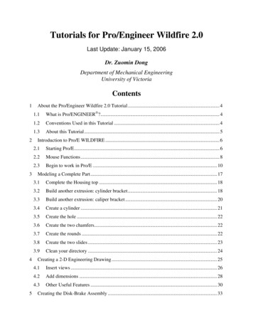
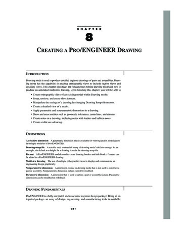
kell c08.qxd6/29/002:41 PMPage 285CHAPTER 8Figure 8–2 Creating a Pro/ENGINEER DrawingANSI A size format and title blockFigure 8–3CREATING A NEW DRAWINGThe Drawing mode option from the New dialog box is used to create new drawings. WhenDrawing mode is selected and a file name entered, Pro/ENGINEER introduces the NewDrawing dialog box (Figure 8–4). If a part or assembly is currently active in session memory, Pro/ENGINEER defaults to this part or assembly as the model from which to createthe drawing. An option is available for browsing to find other existing models. The NewDrawing dialog box provides the option for specifying a standard sheet size or for retrieving an existing format.Three types of items can be added to a drawing: formats, 2D draft entities, and modelviews. Formats are placed in a drawing using Sheets Format Add/Replace. Pro/ENGINEER provides an Open dialog box for browsing to find an appropriate format. TheDetail Sketch option allows for the creation of 2D draft entities. Other options are available for adding dimensions and notes. Model views can be added to a drawing with the View Add option. General, section, projected, auxiliary, revolved, and detail views can be added.The following instructions show step by step how to create a new drawing. Several options are available that can vary the method for creating a new drawing. This processallows for the creation of a new drawing without specifying a standard sheet size from theNew Drawing dialog box.STEP 1: Select FILE NEW.STEP 2: Select Drawing mode from the New dialog box, enter a name for the newdrawing then select OK.STEP 3: On the New Drawing dialog box, locate the OPTIONAL DEFAULTMODEL from which to create the drawing.Pro/ENGINEER defaults to the current active model. You can use the Browseoption to search for any existing object.STEP 4: Select the SET SIZE button from the Specify Sheet option.The Set Size button is selected by default. This option requires defining a285New Format dialog box
kell c08.qxd6/29/002862:41 PMPage 286Drawing ViewsFigure 8–4New Drawing dialog boxsheet size and orientation. The Retrieve Format option allows for the selectionof an existing format. Due to this, the Retrieve Format option does not requirethe selection of a sheet size or orientation.STEP 5: Select a sheet ORIENTATION and a sheet SIZE; then select OK.The Set Size option requires selecting a sheet orientation and size. A portrait,landscape, or variable orientation is available. Standard sheet sizes and userdefined sheets sizes are also available.DRAWING VIEWSPro/ENGINEER’s drawing mode provides options for creating a variety of orthographicviews to include section views, auxiliary views, detailed views, revolved views, brokenviews, and partial views. As many views as necessary to describe a model fully can be addedto a drawing sheet. Once inserted into a drawing, parameters associated with the model, toinclude dimension values, can be created. Views are also fully associated. This allows anymodel changes made in a drawing to be reflected in the part or assembly model. Additionally, changes in one view of a drawing reflects accordingly in all views of the model.THE VIEWS MENUThe Views menu option is used to create views of an existing Pro/ENGINEER model(Figure 8–5). The Views menu has options for manipulating and modifying existing views.The following menu options are available:
kell c08.qxd6/29/002:41 PMPage 287CHAPTER 8 287Creating a Pro/ENGINEER DrawingADD VIEWThe Add View option is used to create new views. The first view created must be aGeneral view. From a General view, other views of the model can be added.MOVE VIEWThe Move View option is used to move views on the work screen. When placing aview, Pro/ENGINEER requests a center point for the drawing view. The view is setinitially at this location. The Move View option can be used to reposition this or anyother view.MODIFY VIEWThe View Modify menu option provides a variety of tools for modifying a view(Figure 8–6). The following is a partial list of the available options: View type The View Type option is available to change the type of view. As anexample, a Projection view can be changed to a General or Auxiliary view. Change scale This option is used to change the scale of a nonchild view. Theview cannot be a child view of another view, and the view must have been insertedwith a specific,
With Pro/ENGINEER, engineering drawings are considered “downstream” applications that occur after part modeling and analysis. Pro/ENGINEER’s basic package provides a module for creating orthographic draw-ings (see Figure 8–1). Within drawing mode, detailed multiview drawings can be created from existing models. Dimensions used to create a part (referred to as parametric dimen- sions .File Size: 1MBPage Count: 69