Transcription
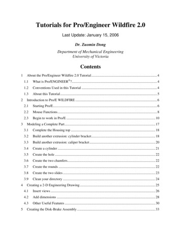
6Creating Drawings inPro/ENGINEERThis chapter shows you how to bring the cell phone models and theassembly you’ve created into the Pro/ENGINEER Drawing mode tocreate a drawing. A mechanical drawing consists of specifically orientedrepresentations of the object being drawn. Each of these representations iscalled a view. There are several types of views, each drawn anddimensioned to show a certain kind or amount of detail.In this exercise you’ll learn how to add an assembly drawing to a bill ofmaterials using the table function. On subsequent sheets you’ll add a fewof the more widely used view types to detail some of the parts. The objectof these exercises is not to create a full drawing of all eight parts. Insteadyou are introduced to the basic workflow of the process of creatingdrawings.First, review the information on dimensions and views in the nextsection, then follow the exercises to create the drawing files.6-1
Understanding Dimensions and AssociativityApplying dimensions to drawing views in Pro/ENGINEER uses adifferent process from that of other programs. The difference is thePro/ENGINEER associativity factor— instead of using the draftingprogram to add a dimension to a view where you need it, you choose toselectively show a dimension that has already been passed, along withthe view, from the 3D model. This dimension is actively linked to the 3Dmodel. As a result, you can directly edit the 3D model through thedimension in the drawing. When shown in the drawing, thesedimensions are called driving dimensions, because they can be used todrive the shape of the model through the drawing.Of course, there will be instances where you need additional dimensionsto show the same value for the same object, for example, a view repeatedon another drawing sheet. To add these, use the Dimensions commandsfrom the Insert menu. These inserted dimensions are called added ordriven dimensions, because their association is only one-way, from themodel to the drawing. If dimensions are changed in the model, all editeddimension values and the drawing are updated.Displaying passed dimensions rather than adding them means yourdrawing will not be overdimensioned and there won’t be any conflictingvalues on different drawing sheets for the same objects. Once drivingdimensions are shown, they can be hidden. They are never permanentlydeleted.The nature of driving dimensions has consequences that a drafter mustbear in mind when making drawings in Pro/ENGINEER:6-2 Only one driving dimension for each model dimension may exist in adrawing. A drawing may have several views of the same object, butonly one driving dimension for each feature of the model can bedisplayed. This is to avoid overdimensioning the drawing and toavoid editing a driving dimension on one sheet but not another. Youcan move a driving dimension from one view to another, for example,from a general view to a detailed view where it is more appropriate.To provide dimensioning for views when driving dimensions are"used up" in other views, you use added driven dimensions. It is possible to unintentionally edit the model. If a driving dimensionis edited, it turns white as a warning that there is a discrepancybetween the drawing and the model. When you regenerate themodel, the drawing accepts the new dimension. The link betweenmodel and drawing can be broken when configuration options havebeen set to do this, but this is not recommended.Getting Started with Pro/ENGINEER Wildfire
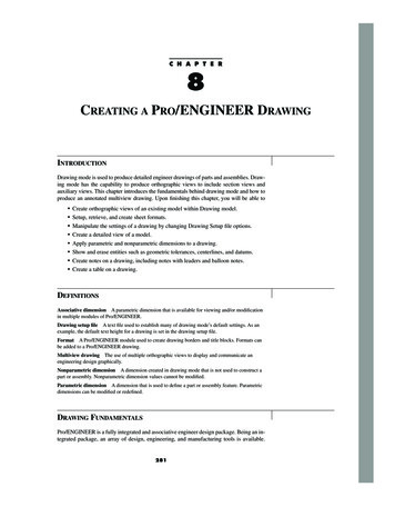
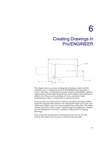
Drawing view of 3D model with no dimensions showingDetail ItemsDimensions are the most important detail items passed from the 3Dmodel, but they are not the only items available or necessary to detail adrawing. In the same way you show or hide dimensions, you can shownotes, surface symbols, geometric tolerances, datum planes, and axes.Adding Models vs. Adding ViewsBefore you can add a view of a model file to a drawing, the model filemust be associated with the drawing file. This is called “adding themodel,” not to be confused with adding a view. You can associate anynumber of models with the drawing, but only one model can be activelyworked on at a time. The active model is the one ready to have viewscreated for it. The active model name appears in the lower-left corner ofthe work area.You add the first model when you create the new file, during the new filesetup. Click File Properties and then Drawing Models Dwg Models Add Model on the Menu Manager to add.If you are working with an assembly, you can use the shortcut menu toadd and activate any of the parts from the Model Tree.Creating Drawings in Pro/ENGINEER6-3
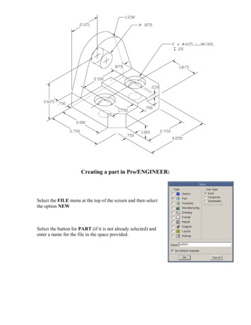
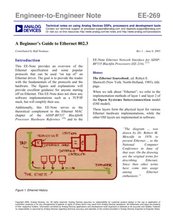
Placing General Views and Projection ViewsThe first view you place will be a type called a general view. You canregard a general view as a parent view because its orientation and scalecan be adjusted, and these properties determine the look of any projectedviews derived from it.Projections (projected views) are views derived from the general view,which show alternate faces of the general view. Using projections you canquickly dimension every surface of a 3D object without repeating adimension. Each projection view exists in either a horizontal or verticalprojection channel to the right, left, above, or below the general view.Projection views are automatically aligned with the general view withintheir projection channels. By default, they can only be moved within thechannels they occupy.General view (center) and four projectionsNoteAlthough alignment with the general view is the usual way to showprojection views, you are not limited to this method. Double-click aprojection view. The Drawing Views dialog box opens. SelectAlignment and uncheck the Align this view to other view checkboxto unalign the selected projection view and place it anywhere on thedrawing sheet.Creating Detailed ViewsA detailed view shows a small area of another view at a larger scale. Theprocess puts a boundary and note around the detailed area on the parentview and creates the new detailed view to a new scale. You can adddriven dimensions, or use the shortcut command Switch View to move adriving dimension from the parent view to the detail view.6-4Getting Started with Pro/ENGINEER Wildfire
Detailed viewScaling Drawings and ViewsPro/ENGINEER automatically determines a scale for a new view basedon the sheet size and the size of the model being placed. This scale valueappears in the lower-left corner of the screen. To reset the scale, clickEdit Value, then click the scale readout and edit the value in the promptline. (A value of 1 means the scale is one-to-one with the actualdimensions, a value of .25 means the drawing is scaled to one-quarter theactual dimensions.)NoteIf necessary, use the default draw scale configuration option toforce a global default scale.Only two view types may be scaled independently of the default scalesetting: the general view and the detailed view. When you rescale ageneral view, its projections also rescale. Because a detailed view is anenlargement of a small area, you can scale a detailed view independentlyof its parent view as well as independently of the default scale.When you place a general view, you choose Scale or No Scale as part ofthe view properties setup in the Menu Manager. If the view is placed asNo Scale (the default) and you later want to change the scale, you mustfirst modify the view type. If your drawing references several parts, youcan set the scale independently for each part added to the drawing.In other words, a default scale is set for each model added to the drawing.The scale readout in the lower-left corner refers to the active model. Anymodifications values for scale, relations, and so forth, are applied to theactive model.Creating Drawings in Pro/ENGINEER6-5
Using Formats and TemplatesFormat files contain the collections of lines and text that border a drawingsheet. These serve to divide the sheet into sections and state the companyname, design name, and so forth. When you associate a format file with anew drawing file, the format graphics appear on all sheets created in thedrawing file. You can also change the format attached to a drawing fileafter the file has been created and saved.There is a default format for each standard sheet size, installed in adefault format directory. To customize a format, save a default format as anew format file, and then add text in the form of notes or graphics, suchas a company logo.Templates are a more advanced concept in Pro/ENGINEER. Templatescontain all the format information and instructions on how to lay outviews and projections automatically, as well as how to create tables andbills of materials. Templates are a powerful functionality that can savehours of interactive work on drawings that follow a standard flow. Youmay use templates in the course of creating drawings eventually, but thisexercise will explain the more basic drawing functions.Creating a New Drawing FileThe finished drawing will have an exploded view of the assembly on thefirst page, with a bill of materials and BOM balloons calling out the parts.However, because these are the more complex elements of the drawing,you’ll add them last. First you’ll add a view of the antenna part to thedrawing. Later in the tutorial you’ll add the assembly view and the BOM.Start the new drawing file:1. Click File New and select Drawing from the New dialog box. Name yourdrawing antenna DR INL PE 1 and clear the Use default template checkbox. Click OK. The New Drawing dialog box opens.2. In the Default Model field, Browse to find your antenna part file.3.In Specify Template, click Empty. Click "Landscape" under orientation.In the Size panel, choose Standard Size, then "A" from the drop down menu.Watch Video6-6Getting Started with Pro/ENGINEER Wildfire
Create a TableNow, you will add a table to the bottom right corner of yourdrawing.Drawing Insert1.Go to Table Insert Table. Choose Descending Rightward By Length Pick Point.2.Click in the area of the bottom right of the Drawing.3.You will be prompted to “Enter the width of the firstcolumn in drawing units ( MM ) [Quit]” in the dialoguejust above the drawing area. Enter 60, then click thecheck mark or hit enter. Since you only need one column,click the check mark or hit enter again. This will promptProE to stop adding columns.4.You will be prompted to “Enter the height of the firstrow in drawing units( MM ) [Quit]” in the dialogue justabove the drawing area. Enter 6, then click the checkmark. Since you want five total rows, repeat the procedurefour more times, then click the check mark or hit enteragain. This will prompt ProE to stop adding rows.5.You can move the table to the bottom right by clicking onthe table and using the arrows to drag it.6.Double Click in the top cell of the table. The NoteProperties box will pop up. Type in Brockton HighSchool, then click OK.Getting Started with ProENGINEER
7.Fill in the rest of the table as it is below, with your name andinformation.8.You can change the size of the text by clicking on the TextStyle tab in the note properties box. Right Click on thetable or cell to bring up the Note Properties box.Watch VideoDrawing InsertGetting Started with ProENGINEER
Now you will add a general view and a projection to the sheet, orient theview, change the view’s properties and show dimensions.1.Click Insert Drawing View General. You are prompted to select acenter point for the drawing view. Click the center-right area of thesheet.2.The view is placed and the Drawing View dialog box opens, showingall the saved 3D orientations. In the dialog box, under Model ViewNames, select Front from the list. Click Apply.3. Under Orientation Method, select Angles. Enter 270 for the anglevalue and click Apply. The view reorients to the horizontal, with thetip pointing to the right. Click OK in the dialog box to close it.4.Under View Display, choose No Hidden in the Display Style box.Watch VideoModify the viewWhen you placed the view, you accepted the default attributes for theview type. Now modify the view for a custom scale.1.Right-click the view and click Properties from the shortcut menu.2.Click Scale from the Categories list, and then choose Custom Scale.Enter 2, and then click Apply and Close. The view is drawn to thenew scale.3.Select the view again, right-click and uncheck Lock View Movementin the shortcut menu. Use the mouse to move the view to a newposition. When the view is placed, check Lock View Movement. Thissetting applies to all of the views on the sheet, not only the selectedview.Now you’ll add the projection view to show the shaft and tip outerdiameters.1.Click Insert Drawing View Projection. Click in the space directlyto the left of the general view. The projection view is added as shownin the next figure.2.to show only theMake sure that your display is set to No Hiddenouter diameter and shaft diameter of the tip. When you changedisplay properties, click the Repaint icon to refresh the display. WatchGeneral view and one projectionCreating Drawings in Pro/ENGINEER6-7Video
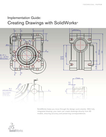
Add the Detailed ViewNow you’ll add the detailed view. This involves a series of prompts thatdefine the elements shown in the following figure.Elements of a detailed viewDetailed viewBoundary circleDetail note1.Click Insert Drawing View Detailed. Click along the outline ofthe tip in the general view. At the spline prompt, use the mouse toclick-draw a circle to enclose the detail to be enlarged. Middle-clickwhen the circle is almost complete. A circle is added around the tip.Sketching the outline for the detailed view6-82.Define the note and leader location by clicking anywhere near thecircle. The note is added at the selected point (it can be dragged toanother position at any time).3.Click in the upper middle of the sheet, and the detailed view isadded. Drag it in any direction to redefine its position.4.Right-click the detailed view, and then choose Properties from theshortcut menu. Choose Scale fr
Pro/ENGINEER associativity factor— instead of using the drafting program to add a dimension to a view where you need it, you choose to selectively show a dimension that has already been passed, along with the view, from the 3D model. This dimension is actively linked to the 3D model. As a result, you can directly edit the 3D model through the dimension in the drawing. When shown in the .File Size: 1014KBPage Count: 22