Transcription
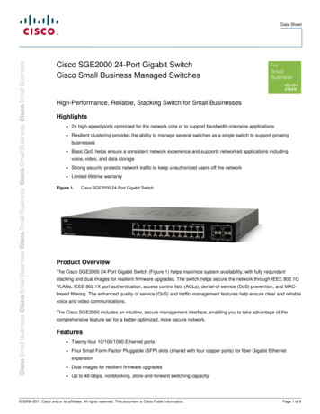
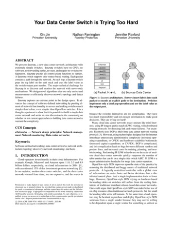
Your Data Center Switch is Trying Too HardXin JinNathan FarringtonJennifer RexfordPrinceton UniversityRockley PhotonicsPrinceton UniversityABSTRACTWe present Sourcey, a new data center network architecture withextremely simple switches. Sourcey switches have no CPUs, nosoftware, no forwarding tables, no state, and require no switch configuration. Sourcey pushes all control plane functions to servers.A Sourcey switch supports only source-based routing. Each packetcontains a path through the network. At each hop, a Sourcey switchpops the top label on the path stack and uses the label value asthe switch output port number. The major technical challenge forSourcey is to discover and monitor the network with server-onlymechanisms. We design novel algorithms that use only end-to-endmeasurements to efficiently discover network topology and detectfailures.Sourcey explores an extreme point in the design space. It advances the concept of software-defined networking by pushing almost all network functionality to servers and making switches muchsimpler than before, even simpler than OpenFlow switches. It is athought experiment to show that it is possible to build a simple datacenter network and seeks to raise discussion in the community onwhether or not current approaches to building data center networkswarrant the complexity.CCS Concepts Networks Network design principles; Network management; Network monitoring; Data center networks;KeywordsSoftware-defined networking; data center networks; network architecture; topology discovery; network monitoring; end hosts1.INTRODUCTIONCloud operators invest heavily in their cloud infrastructure. Forexample, Google, Microsoft and Amazon spent 11.0, 5.3 and 4.9billion dollars, respectively, on cloud infrastructure in 2014 [1],with an estimated 15% of that investment spent on networking [2].In our opinion, modern data center switches, and the data centernetworks created from them, are too expensive, and the reason isPermission to make digital or hard copies of all or part of this work for personal orclassroom use is granted without fee provided that copies are not made or distributedfor profit or commercial advantage and that copies bear this notice and the full citation on the first page. Copyrights for components of this work owned by others thanACM must be honored. Abstracting with credit is permitted. To copy otherwise, or republish, to post on servers or to redistribute to lists, requires prior specific permissionand/or a fee. Request permissions from Permissions@acm.org.c 2016 ACM. ISBN 978-1-4503-4211-7/16/03 . 15.00.DOI: yload(a) Packet: H1è H21H11H2(b) Sourcey Data CenterFigure 1: Sourcey architecture. Servers insert labels into eachpacket to encode an explicit path to the destination. Switchesimplement only a label pop operation and use the label value asthe output port.because the switches themselves are too complicated. They havetoo much responsibility and not enough information to make gooddecisions. They are trying too hard!Many cloud data center networks today operate like mini Internets, using IP longest-prefix match (LPM) routing, with distributedrouting protocols for detecting link and router failures. For example, Facebook uses BGP as their intra-data center network routingprotocol [3]. However, using technologies designed for the Internetintroduces unnecessary administrative complexity (increased operating expenditure, or OPEX) and hardware scalability bottlenecks(increased capital expenditure, or CAPEX). BGP is complicated,and this complication leads to bugs between different vendors andproduct lines, and increased costs for training, planning, and troubleshooting. Performing IP LPM in hardware on the scale of modern cloud data center networks quickly surpasses the number oftable entries that can fit on a single chip switch ASIC. IP LPM is amajor administrative headache for mega data center operators.OpenFlow-style SDN improves upon the state of the practice byremoving the distributed and buggy nature of traditional networkprotocols. A logically centralized controller with a global viewof information can make faster and better decisions than a distributed control plane. And a single implementation leads to fewerbugs. However, OpenFlow-style SDN relying on hardware-basedforwarding tables on switches still suffers from the scaling limitations of traditional merchant silicon-based data center networks.One could argue that OpenFlow-style SDN can make better use ofon-chip resources than traditional network protocols, but the smallforwarding table sizes still remain. At the same time, cloud operators may be hesitant to purchase and deploy OpenFlow-style SDNsolutions from a single vendor because they may not be willingto be dependent upon a single vendor for something as critical as
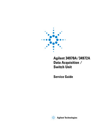
MatchAc(on10.1.0.210.1.0.3Outport 210.1.0.1MatchAc(on1211110.0.0.1PacketH1è H2 22S110.1.0.2Outport 2S3H1S210.1.0.3MatchAc(on10.0.0.2Outport 1Ac(on2Label 3Outport 21S3Ac(on22MatchAc(on21Label 2Output 2113Label 4Outport 11S1S21PacketH1è H2 (a) IP Option1 (b) MPLS Label Swap22S211H2 S3S11H110.0.0.210.1.0.1, 10.1.0.2, 10.1.0.312Match1H2No Forwarding TablesMatch1H2H1PacketH1è H2 1, 2, 2, 1 (c) SourceyFigure 2: Source routing methodologies.their data center network. Finally, OpenFlow itself is getting moreand more complicated. The number of header fields have increasedfrom 12 (OpenFlow Spec 1.0, December 2009 [4]) to 41 (OpenFlow Spec 1.5, December 2014 [5]), which requires switches to implement complicated packet parsers and flow table pipelines. Thenumber of pages of the OpenFlow Spec has also increased from 42pages to 277 pages [4, 5]. Accordingly, OpenFlow software agentson switches are also becoming more complicated.We present Sourcey, a new data center network architecture withextremely simple switches (Figure 1). This paper is a thought experiment to show that it is possible to build reliable, high-performancedata center networks using much simpler switching elements thanwe use today. Sourcey switches are completely stateless. Serversplay a pivotal role by using source routing to choose paths throughthe network. For each packet, a server translates a Layer 2 MACaddress or a Layer 3 IP address into a path, represented as a stackof labels. At each hop, a Sourcey switch pops the top label off ofthe stack, and uses the label value directly as the switch output portnumber, thus avoiding a stateful table lookup. By the time a packetreaches its final destination, the entire path has been removed fromthe packet and the destination sees only an ordinary packet.Sourcey pushes the entire control plane to servers. Switchesonly perform a simple label pop operation. To enable a packetto reach its destination, the control plane needs to tell the serverwhich labels to put into the packet header. The major technicalproblem solved in this paper is how to servers can learn the network topology and keep up-to-date with the latest topographicalchanges, using only server-based mechanisms. This includes twotasks: (i) discover the topology for network bootstrap; and (ii)continuously monitor topology changes to keep update-to-date information. Once the control plane has the topology information,it can implement a wide variety of traffic engineering policies tochoose a routing path for each flow or even each packet. The policies range from distributed ones to centralized ones, as discussedextensively in literature [6, 7, 8, 9].We design new algorithms for Sourcey to perform topology discovery and monitoring. The algorithms run only on servers. Thekey idea is to send probe packets to the network, and by observing the forwarding behavior of probe packets with different labels(whether they return to the sender or not), to infer the topologyand its changes. While it sounds expensive to discover and monitor a entire data center network with server-based probe methods,we show that the carefully-designed algorithms incur low overhead. Especially when compared to high-performance data center networks (10G and 40G are common today), this overhead isnegligible. Furthermore, topology discovery only needs to be conducted during the bootstrap phase. Afterwards, only a small streamof packets are required to detect new elements (links, switches,servers) added to the network and existing elements removed fromthe network (manually or by failure).Source routing is an old idea [10, 11, 12, 13]. The key novelty ofthis paper is the design of the architecture with minimal features onswitches and the accompanied algorithms. In summary, we makethe following two major contributions. Architecture: We present the Sourcey data center networkarchitecture. Switches in this architecture have no CPUs,no software, no forwarding tables, no state, and require noswitch configuration. The entire control plane is pushed toservers. Algorithm: We present novel server-based algorithms to makeSourcey control plane work. The algorithms leverage end-toend probe packets to efficiently infer the network topologyand detect its changes.We view Sourcey as an extreme point in the design space. Itadvances the concept of software-defined networking by pushingalmost all network functionality to servers and making switchesmuch simpler than before, even simpler than OpenFlow switches(which has sophisticated packet parsers, table pipelines, and software agents). With Sourcey, we seek to raise discussion in thecommunity on whether or not current approaches to building datacenter networks warrant the complexity.2.SOURCEY ARCHITECTUREThis section gives an overview of Sourcey. We first describethe source routing in Sourcey and compare it against other sourcerouting methodologies. Then we describe the switch and serverdesign in Sourcey.2.1Source RoutingIn source routing, servers completely or partially specify the pathfor each packet, and put the routing information into packet headers. Switches forward packets based on header information. We illustrate how Sourcey differs from existing source routing solutionsin Figure 2.IP source routing: In IP source routing, servers put IP addressesinto IP option field in each packet header (Figure 2(a)). These IPaddresses either specify the entire path (strict source and recordroute, or SSRR) or specify some hops that the packet must gothrough (loose source and record route, or LSRR). In the example, the packet header contains the IP addresses of switches at eachhop in the IP option field for the packet from server H1 to serverH2 . It requires servers to know the IP addresses of switches at eachhop, and switches to keep an IP forwarding table.MPLS label swap routing: In MPLS label swap routing, serversor ingress switches put an MPLS label on each packet header, andat each hop, the switch forwards the packet based on the label and
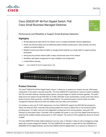
packet inApppoplabeliAppAppTCP/IPStacki is 0addswitchIDtoheaderi is null orport i is inactivedroppacketport i is activeControlPlaneDataPlanesendtooutputportiNIC(a) Sourcey switchdata plane flowchart(b) Sourcey server software stackfor control plane and data planeFigure 3: Sourcey switch and server design.swaps the label to another one (Figure 2(b)). In the example, serverH1 puts MPLS label 1 into the header and the packet goes throughthe network to reach H2 . It requires a centralized controller toproperly compute and configure the flow tables for each switch.Sourcey source routing: Sourcey completely eliminates the flowtable in switches and requires only a label pop function. Servers putlabels for the entire path into each packet header; the label valuesindicates the switch output ports at each hop (Figure 2(c)). Sincedata center networks have small diameters, the overhead of puttinga path into packet headers is small. In the example, server H1 puts[1, 2, 2, 1] into the packet header. The first value denotes the outputNIC port of server H1 , the second value denotes the output port ofswitch S1 , etc. At each hop, switches simply pop off a label anduses the label value as the output port number. It does not requireany configuration of switches.We have to note that only using the label pop function and specifying the entire path at ingress is not a new idea [10, 11, 12, 13].But to make this work, it requires the ingress to know what labelsto put into a packet header. Existing works either assume thereis some sort of an oracle, use distributed protocols, or interactingwith the switch software agents. Differently, Sourcey control planeis entirely on servers and uses server-based mechanisms to learnthe topology.2.2Sourcey SwitchA Sourcey switch has no CPUs, no software, no forwarding tables, no state, and requires no switch configuration. It only implements the simple logic described in Figure 3(a). Switch ports startfrom 1. We reserve port 0 for switch identification. For each arriving packet, the switch pops the first label from the label stack andperforms one of the following actions. Normal case: It forwards the packet to the output port denoted by the label. Error handling: If the label stack is empty or if the label value maps to a nonexistent or failed port, the packet isdropped. Switch identification: If the label is 0, it appends its switchID to the header and uses the next label to decide which output port to forward the packet.Because no software agents run on the switches, the last case is necessary for servers to determine the identity of a switch, which is animportant primitive in the topology discovery algorithms presentedlater.MPLS Compatibility: Sourcey can be made compatible with existing MPLS label switch routers (LSRs). Sourcey labels can usethe MPLS header format. Servers insert MPLS headers betweenthe Ethernet header and IP header (Figure 1). For the special caseof switch identification, MPLS LSRs must be configured to forwardsuch packets to LSR control plane, and let software agents handlesuch packets.2.3Sourcey ServerSourcey servers are responsible for putting labels into each packetheader. To implement this, it requires a control plane that decideswhat labels to push for a packet and a data plane that performs labelpush at line speed, as shown Figure 3(b).Data plane: The data plane is an independent piece of software ateach server. It receives routing decisions from the control plane andpushes labels to each packet based on the routing. The data planehas to handle every packet at line speed. One implementation is as ashim layer below the TCP/IP stack. Existing applications then neednot be modified. Implementation choices include in kernel space,integration with the NIC as firmware or hardware, and integrationwith the hypervisor in virtualized environments.Control plane: The control plane is a distributed system that runson all servers. It discovers the network topology, monitors the network status, and chooses routes for each flow or packet.The major technical problem is topology discovery and monitoring. Once the control plane has an updated view of the topology, itis possible to choose routes for each flow or packet with differenttraffic engineering policies, as discussed in [6, 7, 8, 9]. In the remainder of this paper, we focus on how to implement topology discovery and topology monitoring using server-based mechanisms.3.SOURCEY CONTROL PLANEThere are two major problems to be solved by the control plane.First, the control plane needs to discover the network topology during bootstrap, so that servers know what labels to use to implementa routing path. Second, the control plane needs to monitor the network and have an up-to-date view of the topology, so that trafficengineering can quickly switch to different paths in face of topology changes. This section describes server-based mechanisms tosolve them.3.1Topology DiscoveryBasic idea: Since the control plane exists entirely on servers, wecan not run any distributed protocols on switches to discover thetopology. We can only rely on servers. The basic idea is to sendprobe packets to the network and infer the network topology by
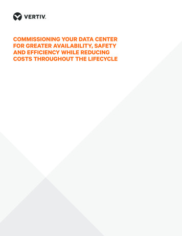
S311 2223S11S412S21(a) Discover S123S11H211 23[1, 0, 1]H1S32[1, 2, 0,1, 1]11H1[1, 3, 0,1, 1]S4S33211p 1:[1, 2, 2, 0,2, 1, 1]1S21H211 22(b) Discover S3 and S43S1H1S31 2132211p 3:[1, 3, 2, 0,3, 1, 1]122p 2:[1, 2, 2, 0,3, 1, 1]S4S23S11p 4:[1, 3, 2, 0,2, 1, 1]H1H2(c) Discover S2S423S211H2(d) Discover S2Figure 4: Example of topology discovery.observing the behavior of these packets (whether they return to thesender or not). A naive way is to send packets with all combinationsof labels to the network and build the topology based on their behavior. The overhead of this solution increases exponentially withthe maximum number of hops of the network. To make the problem tractable, we use breadth-first search (BFS). A server graduallyexplores the network and learns the topology, rather than exploringthe entire topology in one shot. This prunes many branches fromthe search space.Example: To make the idea more concrete, we describe an example shown in Figure 4. Suppose, server H1 performs the topologydiscovery. Initially, it only knows about itself.Discover S1 : Server H1 sends probe packets with label stack[1, 0, j] to learn its neighbor (the first label is 1 because server Honly has one NIC) where 1 j M AX P ORT and M AX P ORTis the maximum port count of a switch. The label 0 is used to querythe switch ID that server H1 is connected to. Only the packet withlabel stack [1, 0, 1] returns to server H1 . This tells server H1 that itis connected to switch S1 on port 1.Discover S3 and S4 : After discovering switch S1 , server H1sends probe packets to discover switches two hops away. The probepackets have label stack [1, i, 0, j, 1] where 1 i, j M AX P ORT .The first label 1 in the stack is used to reach switch S1 ; the lastlabel 1 is used to return to server H1 from switch S1 ; the middlelabels [i, 0, j] are used for discovery. Packets with [1, 2, 0, 1, 1] and[1, 3, 0, 1, 1] return to server H1 , and server H1 learns link S1 -S3and link S1 -S4 .Discover S2 : Now server H1 sends probe packets to discoverswitches three hops away. Since there are two switches (S3 andS4 ) that are two hops away, the probe packets need to go one hopbeyond each of them. To go beyond S3 , the probe packets use labelstacks [1, 2, i, 0, j, 1, 1]; to go beyond S4 , the probe packets uselabel stacks [1, 3, i, 0, j, 1, 1]. The following four packets wouldreturn to server H1 . p1 : [1, 2, 2, 0, 2, 1, 1]. p2 : [1, 2, 2, 0, 3, 1, 1]. p3 : [1, 3, 2, 0, 3, 1, 1]. p4 : [1, 3, 2, 0, 2, 1, 1].Only looking at these packets, packet p1 suggests port 2 on switchS3 is connected to port 2 on switch S2 ; packet p2 suggests port 2on switch S3 is connected to port 3 on switch S2 . They are conflicting with each other. If we look at the paths they traverse, wecan see that packet p1 uses H1 -S1 -S3 -S2 -S3 -S1 -H1 and p2 usesH1 -S1 -S3 -S2 -S4 -S1 -H1 . The return path of p2 is not the same asthe departure path. To resolve this conflict, we need to send another two probe packets, one with label stack [1, 2, 2, 2, 0, 1, 1] andthe other with label stack [1, 2, 2, 3, 0, 1, 1]. They would query theswitch ID of the first switch on the return path. From them, weknow that p1 uses the same path for the round trip and p2 does not.Therefore, port 2 on switch S3 is connected to port 2 on switch S2 .H1 11S12132S2Figure 5: Example for parallel links.Similarly, for p3 and p4 we need to send additional probe packetsto determine link S4 -S2 .Discover H2 : Finally, server H1 sends probe packets to discovernodes four hops away. Since there is only one switch three hopsaway, the probe packets use label stacks [1, 2, 2, i, 0, j, 2, 1, 1]. Theprobe packet with label stack [1, 2, 2, 1, 0, 1, 2, 1, 1] would returnto server H1 with the ID of server H2 . This finishes the topologydiscovery process.Special case - parallel links: When there are multiple link betweentwo switc
from 12 (OpenFlow Spec 1.0, December 2009 [4]) to 41 (Open-Flow Spec 1.5, December 2014 [5]), which requires switches to im-plement complicated packet parsers and flow table pipelines. The number of pages of the OpenFlow Spec has also increased from 42 pages to 277 pages [4, 5]. Accordingly, OpenFlow software agents