Transcription
Grid Interconnection andPerformance TestingProcedures for Vehicle-To-Grid(V2G) Power ElectronicsPreprintWilliam Kramer, Sudipta Chakraborty,Benjamin Kroposki, Andy Hoke, Greg Martin,and Tony MarkelTo be presented at the World Renewable Energy Forum 2012Denver, ColoradoMay 13-17, 2012NREL is a national laboratory of the U.S. Department of Energy, Office of EnergyEfficiency & Renewable Energy, operated by the Alliance for Sustainable Energy, LLC.Conference PaperNREL/CP-5500-54505March 2012Contract No. DE-AC36-08GO28308
NOTICEThe submitted manuscript has been offered by an employee of the Alliance for Sustainable Energy, LLC(Alliance), a contractor of the US Government under Contract No. DE-AC36-08GO28308. Accordingly, the USGovernment and Alliance retain a nonexclusive royalty-free license to publish or reproduce the published form ofthis contribution, or allow others to do so, for US Government purposes.This report was prepared as an account of work sponsored by an agency of the United States government.Neither the United States government nor any agency thereof, nor any of their employees, makes any warranty,express or implied, or assumes any legal liability or responsibility for the accuracy, completeness, or usefulness ofany information, apparatus, product, or process disclosed, or represents that its use would not infringe privatelyowned rights. Reference herein to any specific commercial product, process, or service by trade name,trademark, manufacturer, or otherwise does not necessarily constitute or imply its endorsement, recommendation,or favoring by the United States government or any agency thereof. The views and opinions of authorsexpressed herein do not necessarily state or reflect those of the United States government or any agency thereof.Available electronically at http://www.osti.gov/bridgeAvailable for a processing fee to U.S. Department of Energyand its contractors, in paper, from:U.S. Department of EnergyOffice of Scientific and Technical InformationP.O. Box 62Oak Ridge, TN 37831-0062phone: 865.576.8401fax: 865.576.5728email: mailto:reports@adonis.osti.govAvailable for sale to the public, in paper, from:U.S. Department of CommerceNational Technical Information Service5285 Port Royal RoadSpringfield, VA 22161phone: 800.553.6847fax: 703.605.6900email: orders@ntis.fedworld.govonline ordering: http://www.ntis.gov/help/ordermethods.aspxCover Photos: (left to right) PIX 16416, PIX 17423, PIX 16560, PIX 17613, PIX 17436, PIX 17721Printed on paper containing at least 50% wastepaper, including 10% post consumer waste.
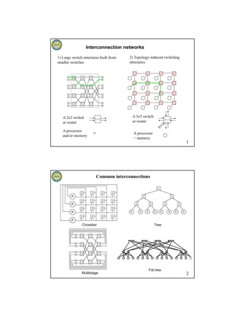
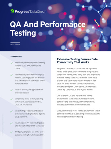
GRID INTERCONNECTION AND PERFORMANCE TESTING PROCEDURES FOR VEHICLETO-GRID (V2G) POWER ELECTRONICSWilliam KramerSudipta ChakrabortyBenjamin KroposkiAndy HokeGreg MartinTony MarkelNational Renewable Energy Laboratory1617 Cole Blvd., Golden, CO govABSTRACTdefined as being vehicle-to-grid (V2G) capable. Possibleuses of V2G vehicles for distributed energy applications areto provide power to utility/local loads, regulate voltage andfrequency, offer spinning reserves, and enable electricaldemand management. Electric, plug-in hybrid, and V2Gvehicles will have the potential to absorb excess electricityproduced by renewable energy sources (e.g., wind orphotovoltaics) when the grid is operated at low loadconditions [2].Bidirectional power electronics can add vehicle-to-grid(V2G) capability in a plug-in vehicle, which then allows thevehicle to operate as a distributed resource (DR). Theuniqueness of the battery-based V2G power electronicsrequires a test procedure that will not only maintain IEEEinterconnection standards, but can also evaluate theelectrical performance of the vehicle working as a DR. Theobjective of this paper is to discuss a recently publishedNREL technical report that provides interim test proceduresfor V2G vehicles for their integration into the electricaldistribution systems and for their performance in terms ofcontinuous output power, efficiency, and losses.Additionally, some other test procedures are discussed thatare applicable to a V2G vehicle that desires to providepower reserve functions. A few sample test results areprovided based on testing of prototype V2G vehicles atNREL.1.V2G vehicles utilize a reliable, high-power, high-energybattery pack with bidirectional power electronics andcontroller. The controller module controls the powerelectronics to operate in charge, discharge, or standbymodes. The first commercial V2G vehicles are expected touse either a nickel metal hydride or a lithium-ion batterypack to obtain high energy densities [2]. The block diagramof a fully electric vehicle with V2G capability is shown inFig. 1. In this configuration, the utility connection is madeusing the same power electronics that are used for thetraction motor/generator (M/G), thus eliminating the needfor a separate battery charger.INTRODUCTIONThough V2G functionalities are expected to be the same fordifferent vehicles, the specific V2G system configurationcan be different depending on the details of the vehicledesign, such as fully electric or hybrid; the powerelectronics topologies; and the type of power and controlconnections. Irrespective of their design, all vehicles withV2G capability must meet IEEE Std. 1547 (referred asIEEE 1547 hereafter) “Standard for InterconnectingDistributed Resources with Electric Power Systems,” whichOver the past 15 years, energy storage technologies forvehicle traction systems have improved dramatically andfound their way into commercially viable hybrid, electric,and plug-in hybrid vehicles. Typical electric or plug-inhybrid vehicles use power electronics to charge the batteriesdirectly from the utility, thus increasing the all-electricdriving range for the electric or hybrid vehicles [1]. Powerelectronics can also be designed so that power can be fedback to the grid. A vehicle with this type of technology is1
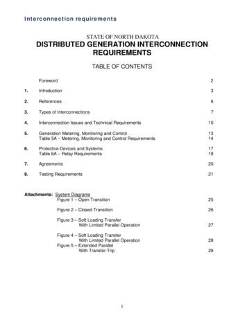
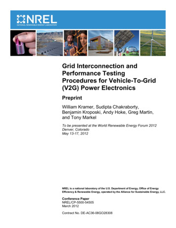
procedures. The required information includes: type ofvehicle propulsion, power electronics topology, type andsize of the battery, battery terminal voltage, utilityconnection voltage level(s) and frequency, output power,charging rate and time, type of power connectors,charge/discharge control methods, type of on-board dataacquisition, and display and electrical safety systems [4].specifies the type, production, and commissioning tests thatmust be performed to demonstrate that the utilityinterconnection functions properly [3].The objective of this paper is to discuss a recently publishedNREL technical report [4] that provides interim testprocedures for V2G vehicles. The NREL test plan wasdesigned to test and evaluate a vehicle’s capability toprovide power to the grid, and to evaluate the vehicle’sability to connect and disconnect from the utility accordingto a subset of the IEEE 1547 tests [4]. Some additionalperformance tests were included in the test plan to verifythe V2G-capable vehicle’s continuous output power,efficiency, and losses [4]. It is important to note that almostall the tests described in that report were for V2G modesonly, not for modes in which the vehicle was charging itsbatteries from the grid [4]. Once validated, these procedurescould become the basis for testing standards for V2Gapplications.An example of a test setup for a V2G-capable electricvehicle is shown in Fig. 2 [4]. This configuration has asingle-phase connection to the utility grid. A programmableAC grid simulator is used to emulate the electric utility.This grid simulator is controlled by a computer and iscapable of outputting voltage waveform sequences. As thegrid simulator can not sink power, a variable load bank isused in parallel. In this particular vehicle under test, thecharging/discharging is controlled using cellular signals.For safety reasons, a manual disconnect is included in thetest system that can disconnect the batteries from the utilityconnection in case of emergency.The general requirements for the test procedure are asfollows: (1) Implementation of these test procedures shallbe conducted in accordance with appropriate safetyprocedures, sequences and precautions. (2) Themanufacturer shall specify the range of environmentalconditions for the equipment under test. The tests shall beconducted in an environment that is within themanufacturer’s specified environmental operatingconditions. (3) Measurement equipment used to confirmperformance shall have calibration traceability. Theaccuracy of the measuring equipment shall be suitable forthe test being conducted. (4) The test results shall bedocumented in a test report. The test report shall includesufficient critical operating information to rerun the test andreproduce the results. (5) Each test method shall bespecified, and engineering considerations, including rangeof operating conditions, shall be justified.Fig. 1: Block diagram of an electric vehicle with V2G2.TEST SETUP AND REQUIREMENTSThe manufacturers’ specifications for the V2G-capablevehicle are important in designing the test plan andCell TowerV2G ControlComputer12 eAC Grid SimulatorBattery Charger yMotorControllerM/GWheelVariableRLC Load BankBattery Charge/Discharge ControlPLUG-IN VEHICLE WITH V2G CAPABILITYFig. 2: Example of V2G test setup2
3.GRID INTERCONNECTION TESTS3.3 Synchronization and Seamless TransferThis section discusses various tests to determine the safeV2G interconnection to the utility grid. Most of these testsare described based on the IEEE Std. 1547.1-2005 (referredas IEEE 1547.1 hereafter) that gives the conformance testprocedures for equipment that interconnects distributedresources with electric power systems [5]. Some of theIEEE 1547.1 tests are unfeasible or redundant for V2Gpower electronics and are discussed as additional tests atthe end of this section. The tests described in this sectionare in the order in which they are suggested in IEEE 1547,Table 4. It is important to note that V2G vehicles may becapable of connecting to the utility at different voltagelevels (e.g. 120 V, 240 VAC rms); therefore, all of theinterconnection testing discussed in this report will need tobe conducted for all practical utility connection voltages.To properly interconnect with the utility, V2G convertersmust properly synchronize causing minimal systemtransients. If the unit can also supply a load independentlyof the utility status, the voltage and frequency supplied tothe load must also be free of significant transients duringthe transfer process, regardless of the inverter’s initialconditions and power exporting status prior to the shift.Two basic test methods are provided in IEEE 1547.1,section 5.4. If the V2G power electronics can generate avoltage independently of the utility and are thus capable ofout-of-phase paralleling (e.g., operating in a stand-alonemode), the unit must be tested using Method 1 to verify itssynchronizing capability. The V2G power electronics thatare not able to supply power independent of the utility mustbe tested to determine the synchronization current usingMethod 2. The detailed test procedure can be found in IEEE1547.1, section 5.4.3.1 Response to Abnormal Voltages3.4 Unintentional IslandingThis series of tests is used to ensure the V2G powerelectronics disconnect from the utility whenever voltagelevels go out to the ranges specified in IEEE 1547. TheV2G must not only disconnect from the utility when avoltage threshold is reached, but must also disconnectwithin the amount of time specified in Table 1 of IEEE1547. This procedure uses the ramp and step functionsdefined in IEEE 1547.1, Annex A. This procedure shouldbe repeated to test for both over and under voltageconditions. This procedure has two parts: 1) a magnitudetest to determine the grid voltage magnitude at which theinverter disconnects, and 2) a time test to determine thetime it takes the inverter to disconnect after the voltagerange has been exceeded. The detailed test procedure can befound in IEEE 1547.1, section 5.2.The purpose of this test is to verify that the V2G powerelectronics cease to energize the utility as specified in IEEE1547 when an unintentional island condition is present.This test determines the trip time for the test conditions andconfirms that the trip time is within two seconds of theformation of an island as specified in IEEE 1547. This testprocedure is designed to be universally applicable to alldistributed resources, regardless of output power factor.Any reactive power compensation by the V2G convertershould remain on during the test. Where the V2Gmanufacturer requires an external or separate transformer,the transformer should be connected between the V2G andresistive-inductive-capacitive (RLC) load and should beconsidered part of the product being tested. The detailedtest procedure can be found in IEEE 1547.1, section 5.7. Itis important to note that steps ‘n’ and ‘o’ of the antiislanding tests in IEEE 1547.1 cannot be performed forsome V2G interconnection equipment because both theinput power from the battery and the output power level arenot adjustable. When this is the case, it should be notedclearly in the test report.3.2 Response to Abnormal FrequenciesThis series of tests is used to ensure the V2G powerelectronics disconnect from the utility whenever thefrequency falls outside of the ranges specified in IEEE1547. Again, the V2G vehicle must not only disconnectfrom the utility when a frequency threshold is reached, butmust also disconnect within the amount of time specified inIEEE 1547, Table 2. This procedure uses the ramp and stepfunctions defined in IEEE 1547.1, Annex A. This procedureshould be repeated to test for both over and under frequencyconditions. This procedure has two parts: 1) a magnitudetest to determine the frequency threshold at which theinverter disconnects, and 2) a time test to determine thetime it takes the inverter to disconnect after the frequencythreshold h
conditions. This procedure has two parts: 1) a magnitude test to determine the grid voltage magnitude at which the inverter disconnects, and 2) a time test to determine the time it takes the inverter to disconnect after the voltage range has been exceeded. The detailed test procedure can be