Transcription
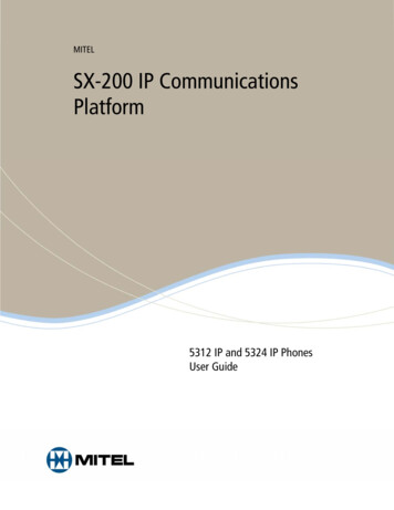
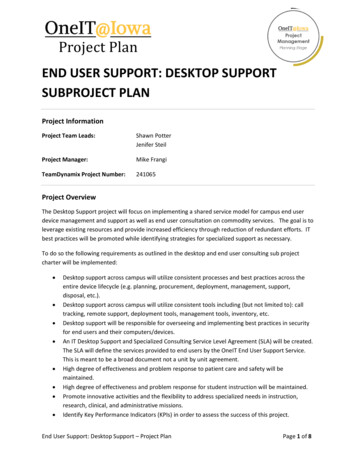
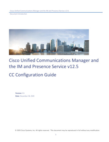
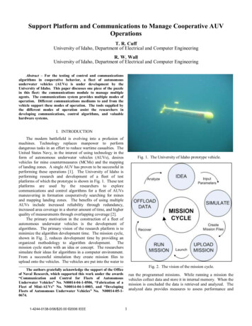
Support Platform and Communications to Manage Cooperative AUVOperationsT. R. CuffUniversity of Idaho, Department of Electrical and Computer EngineeringR. W. WallUniversity of Idaho, Department of Electrical and Computer EngineeringAbstract – For the testing of control and communicationsalgorithms in cooperative behavior, a fleet of autonomousunderwater vehicles (AUVs) is under development by theUniversity of Idaho. This paper discusses one piece of the puzzlein this fleet: the communications module to manage multipleagents. The communications system provides multiple modes ofoperation. Different communications mediums to and from thevehicle support these modes of operation. The tools supplied bythe different modes of operation assist the researchers indeveloping communications, control algorithms, and valuablehardware systems.I. INTRODUCTIONThe modern battlefield is evolving into a profusion ofmachines. Technology replaces manpower to performdangerous tasks in an effort to reduce wartime casualties. TheUnited States Navy, in the interest of using technology in theform of autonomous underwater vehicles (AUVs), desiresvehicles for mine countermeasures (MCMs) and the mappingof landing zones. A single AUV has proven to be successful inperforming these operations [1]. The University of Idaho isperforming research and development of a fleet of testplatforms of which the prototype is shown in Fig. 1. These testplatforms are used by the researchers to explorecommunications and control algorithms for a fleet of AUVsmaneuvering in formation cooperatively searching for minesand mapping landing zones. The benefits of using multipleAUVs include increased reliability through redundancy,increased area coverage in a shorter amount of time, and higherquality of measurements through overlapping coverage [2].The primary motivation in the construction of a fleet ofautonomous underwater vehicles is the development ofalgorithms. The primary vision of the research platform is tominimize the algorithm development time. The mission cycle,shown in Fig. 2, reduces development time by providing anorganized methodology to algorithm development.Themission cycle starts with an idea or concept. The researcherssimulate their ideas for algorithms in a computer environment.From a successful simulation they create mission files toupload onto the vehicles. The vehicles are put into the water toFig. 1. The University of Idaho prototype vehicle.Fig. 2. The vision of the mission cycle.The authors gratefully acknowledge the support of the Officeof Naval Research, which supported this work under the awards“Communication and Control for Fleets of AutonomousUnderwater Vehicles” No. N00014-04-1-0506, “Fabrication of aFleet of Mini-AUVs” No. N00014-04-1-0803, and “DevelopingFleets of Autonomous Underwater Vehicles” No. N00014-05-10674.1-4244-0138-0/06/ 20.00 2006 IEEErun the programmed missions. While running a mission thevehicles collect data and store it in internal memory. When themission is concluded the data is retrieved and analyzed. Theanalyzed data provides measures to assess performance and1
Form ApprovedOMB No. 0704-0188Report Documentation PagePublic reporting burden for the collection of information is estimated to average 1 hour per response, including the time for reviewing instructions, searching existing data sources, gathering andmaintaining the data needed, and completing and reviewing the collection of information. Send comments regarding this burden estimate or any other aspect of this collection of information,including suggestions for reducing this burden, to Washington Headquarters Services, Directorate for Information Operations and Reports, 1215 Jefferson Davis Highway, Suite 1204, ArlingtonVA 22202-4302. Respondents should be aware that notwithstanding any other provision of law, no person shall be subject to a penalty for failing to comply with a collection of information if itdoes not display a currently valid OMB control number.1. REPORT DATE3. DATES COVERED2. REPORT TYPE200600-00-2006 to 00-00-20064. TITLE AND SUBTITLE5a. CONTRACT NUMBERSupport Platform and Communications to Manage Cooperative AUVOperations5b. GRANT NUMBER5c. PROGRAM ELEMENT NUMBER6. AUTHOR(S)5d. PROJECT NUMBER5e. TASK NUMBER5f. WORK UNIT NUMBER7. PERFORMING ORGANIZATION NAME(S) AND ADDRESS(ES)University of Idaho,Department of Electrical and ComputerEngineering,Moscow,ID,838449. SPONSORING/MONITORING AGENCY NAME(S) AND ADDRESS(ES)8. PERFORMING ORGANIZATIONREPORT NUMBER10. SPONSOR/MONITOR’S ACRONYM(S)11. SPONSOR/MONITOR’S REPORTNUMBER(S)12. DISTRIBUTION/AVAILABILITY STATEMENTApproved for public release; distribution unlimited13. SUPPLEMENTARY NOTESThe original document contains color images.14. ABSTRACT15. SUBJECT TERMS16. SECURITY CLASSIFICATION OF:17. LIMITATION OFABSTRACTa. REPORTb. ABSTRACTc. THIS PAGEunclassifiedunclassifiedunclassified18. NUMBEROF PAGES19a. NAME OFRESPONSIBLE PERSON8Standard Form 298 (Rev. 8-98)Prescribed by ANSI Std Z39-18
insights into ways improve algorithms for another missioncycle.This paper focuses on the vehicle’s communicationsmodule and its external communications channels as well asthe proprietary fleet management software used in surfaceoperations for the test platform. The communications moduleprovides three modes of operation supported by threecommunication mediums external to the vehicle and oneinternal. The internal channel leads to a distributed networksupported by Ethernet using TCP/IP and UDP protocols. Thedistributed control network passes messages betweenmicroprocessor nodes within the vehicle. As this is the topic ofanother paper [3], little else will be said about the internalnetwork.The external channels provide three methods forcommunicating with the world outside the vehicle. Onemethod, referred to as the real-time communications channel,provides real-time fleet management of the vehicles while onthe surface and between autonomous missions. Anothermethod configures the vehicles prior to running an autonomousmission and downloads the data gathered after an autonomousmission is complete. The user connects through web pages,served by the vehicle itself, to configure systems and downloaddata. The final method communicates through an acousticmodem. The modem serves two purposes: it acts as a sensorfor navigation by calculating position based off of LongBaseLine (LBL) active navigation and it provides the mediumfor communications between vehicles operating in autonomousmission mode.Fig. 3. The real-time communications hardware.for serial communications. As mentioned earlier, the Ethernetport provides connectivity to the internal distributed network.A laptop computer, running the Windows XP operatingsystem (OS), a joystick, and a global positioning system (GPS)receiver complete the hardware and act as the base station.The joystick is an optional tool because all joystick controlshave a related keyboard command (the joystick is favored overkeyboard control for its obvious ease of use). A laptop, asopposed to a desktop computer, provides mobility and overtwo hours of battery operation in case a power source becomesunavailable. This seemingly minor feature has the benefit ofallowing users to locate and recover vehicles when externalpower is not available.II. REAL-TIME COMMUNICATIONSBetween missions the user needs the ability to control thevehicle into a position away from obstacles. The real-timecommunications link and proprietary control software providesthis function, using the keyboard, mouse, or joystick for userinput. Other functions include the real-time display oftelemetry and surface position information, the ability to startand abort missions, and the data display and control of up toeight AUVs.B. SoftwareThe real-time communications software on the vehicleconveys messages between devices on the internal distributednetwork and the radio modem. Every 500 milliseconds thedata from the sensors, along with mission state and local x- andy-coordinates, gets formed into packet. This packet is taggedwith a message identifier and vehicle identification number andtransmitted via the radio modem. There are currently threetypes of messages received by the radio modem from thelaptop. The first kind of message controls fin positions andmotor speed. These messages are sent directly to themotor/servo controller. The other two messages are the startand abort mission messages, which are sent to the autonomousvehicle controller, or the ‘brain’ of the vehicle. The startmission message contains a number identifying the number ofthe mission to start. How these different missions get into thevehicle controller is mentioned later. Abort mission messagesobviously are passed to the controller to tell it to stop thecurrently running mission, which is useful if the user noticesthe vehicle behaving inappropriately and the radio modem isstill in contact with the vehicle.The software Graphical User Interface (GUI) is aWindows OS executable. The inputs to the program comeA. Hardware (Fig. 3.)A pair of model 9XStream [4] wireless radio modemsmade by MaxStream, provides the wireless communicationslink. The 9XStream model operates at a frequency of 900MHzand transmits data at 9600 baud. A Yagi high-gain, directionalantenna on the base station provides a maximum range of 32kilometers, line-of-sight and in optimum conditions. In somecases the radio signal is capable of penetrating the surface ofthe water to a depth of 0.5 meters that proved invaluable duringthe initial design phase of the vehicle.On the vehicle, a RCM3000 [5] microcontroller, made byRabbit Semiconductor, provides the link from devices internalto the vehicle to devices external. The RCM3000 (RCMstands for Rabbit Core Module) operates at 29.4 MHz, has onemegabyte of memory evenly divided between flash andSRAM, and makes available an Ethernet port and other pins2
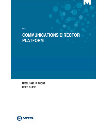
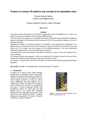
Fig. 4. Screenshot of AUV Control Panel software.from the mouse, keyboard, joystick, and the radio modemattached via the Universal Serial Bus (USB). The outputs arethe display and the control packets that are sent out the radiomodem.of the antenna, this data is displayed on the screen.Theoretically, the GUI can display data for 14336 vehicles (7hopping channels 256 networks 8 vehicles per network).This is in theory, but the reality of it is that there are limitationsin the radio frequency channel. Fig. 4, shows the reception ofdata from vehicles #1 and #3 that are on network zero usinghopping channel one. The telemetry data includes:C. FeaturesFig. 4 is a sample screenshot of the AUV Control Panelwhile in action. The incoming telemetry data for two vehiclesare displayed with vehicle #3 having the focus for controlcommands. The thicker border around the data indicates thefocus for control commands. The features and their benefitsfor the AUV Control Panel are now enumerated using Fig. 4,as an example. 1) Real-time display of telemetry dataWhen the vehicles are active and on the surface, theytransmit specific data indicating position, orientation andinternal telemetry. If the vehicle and the GUI are configuredfor the same network (256 networks available), the samehopping channel (seven channels available), and within range 3GPS information - latitude, longitude, heading,velocity, and Horizontal Position Error (HPE).Depth.Compass information – heading, dip, pitch, and roll.Yaw rate.Accelerometer information – pitch and roll (used ingyrocompass graphic).Velocity from a flow sensor.Environmental information – battery voltage, current,and state of charge; temperature inside the vehicle.Mission mode state – out, in, or initializing.
Local x-coordinate and y-coordinate in meters asdetermined by LBL.Gyrocompass graphic – visual feedback of vehicleheading (from compass), pitch, and roll (fromaccelerometers).2) Real-time vehicle controlResearchers need the ability to control the vehicles duringlaunch of and recovery from missions. To this end, the ControlPanel sends control messages, via the real-time wirelesscommunications, to the vehicles. Fig. 4, shows telemetry dataarriving from two different vehicles. Either of these vehiclesor both can be controlled with joystick or keyboard commandswhen they have the focus. The user sets the focus to individualvehicles to control them into the starting point for missions andselects multiple vehicles when the user starts multiple vehicleson the same mission or controls the vehicles concurrently.Fig. 5. Master (left) and slave (right) controllerhardware. The master controls the wireless Ethernet.3) Commanded feedbackCommanded rudder and planes positions along withcommanded engine power (represented as a percentage) aredisplayed in the upper left corner of the screen. The antennasymbol in the extreme upper left corner indicates that the radiois actively sending and receiving data. A digital clock of thecurrent system time assists in tracking mission start times.Specifying a mission number in the scroll box (Fig. 4) andselecting the ‘Start Mission’ button on the screen will send themessage to start the mission. Pulling the trigger on the joysticksends an abort mission command. All previously mentionedcontrols have equivalent keyboard commands and affect theselected vehicle(s) equally.A. Hardware (Fig. 5.)A Linksys model WCF12 [6] wireless CompactFlash cardprovides the wireless Ethernet link. The CompactFlash plugsinto a Type 1 slot and makes available a link using the 802.11bstandard, operating at 2.4GHz.On the vehicle, a Rabbit Semiconductor RCM3100 [7]microcontroller provides the link between a slavemicrocontroller (the same microcontroller used for thepreviously described real-time communications) and thewireless CompactFlash card. The RCM3100 Rabbit CoreModule operates at 29.4 MHz, has one megabyte of memoryevenly divided between flash and SRAM, and has pins forconnecting to a slave device and an external memory device.The wireless CompactFlash card gets accessed like an externalmemory device.Any properly configured computer with a wirelessEthernet card can acquire the ad hoc connection. The samelaptop providing real-time communications accesses thewireless Ethernet.4) Top-side trackingEvery vehicle has the capability of reporting its GPS datawhen its GPS receiver is unobstructed from the satellites. ThisGPS data, along with the GPS data for the base station, helps tolocate the position(s) of the vehicle(s) relative to the basestation. As of the writing of this paper, this feature is stillunder development and the image in the upper left corner ismerely a placeholder for where the user will eventually see theGPS information displayed. The ability to locate the vehiclesat mission end assists in their recovery.B. SoftwareA special software packet driver library for controlling thepins of the CompactFlash card is available from RabbitSemiconductor. This driver provides the necessary functionsfor using most any TCP/IP communications protocol. Thewireless Ethernet uses Hypertext Transfer Protocol (HTTP) forserving up web pages and File Transfer Protocol (FTP) for datadownload. Most of the web pages are created statically(HTML files are created before compile time) and compiledinto the flash memory.Other web pages are createddynamically at run-time, using current data from inside thevehicle. For example, the different runs that are stored in thedata log are displayed in a table format created at run-time sothat the user can select a link to choose a log for FTPdownload.As mentioned before, any properly configured computercan link to the wireless network card and access informationfrom a vehicle. The user needs only to start a web browser andIII. MISSION CONFIGURATION AND DATADOWNLOADWith the vehicle in the laboratory or on the dock in thestaging area, researchers need the ability to configure thevehicle and download its mission data log. A wireless Ethernetconnection with web pages served up by the vehicle itselfprovides this function. Using a wireless form of access to thevehicle’s data reduces wear and tear on the seals that keep thevehicle watertight. The short range of wireless Ethernetdoesn’t permit real-time, long-range control of the vehicles butthe high-speed connection permits fast data download whilethe vehicle is close.4
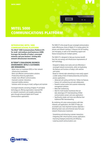
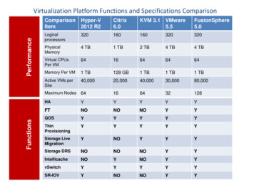
Fig. 6. Screenshot of home page for vehicle #1.link to the static IP address of the vehicle. Once on the homepage, the user can click on links in navigation bar (left side ofFig 6.) to access other information stored on the vehicle. Nospecial software is required on the PC to access thisinformation.status for the depth sensor and the ability to calibrate the depthsensor.A set of indicator lights shows the status of the slave, theradio modem, and the acoustic modem. Clicking the resetbutton on the screen does a power off reset of the slavecommunications. This feature proved invaluable duringdevelopment when a coding error for the internal networkoccasionally caused the slave processor to stop working. Thelast bit of information on the navigation bar is the serialnumber for the vehicle. This value is simply the Media AccessControl (MAC) address for the wireless Ethernet card, which isthe unique 48-bit address, assigned to all Ethernet devices.C. FeaturesFigs. 6,7, are example screenshots of actual web pages thatare served by a vehicle. Fig. 6, is the home page while Fig.7,is an example of the data download page. The features andbenefits of the varying web pages are now enumerated usingthe Figs. 6,7, as reference.2) Home PageThe home page identifies the project by displaying apicture of the vehicle. The home page also displays the currentcommunications configuration. As mentioned in the real-timecommunications section, the vehicle number, the network, andthe address are all used to identify this vehicle to the AUVControl Panel. The vehicle number is also used to identify thisvehicle on the acoustics network (described later).1) Navigation BarThe navigation bar is available in the left column of everypage and makes available links to the different ‘departments’on the vehicle. A ‘department’ defines an area of the vehiclewhere information (configuration or status) resides. Forexample, at the ‘department Science Station’ link resides the5
Fig. 7. Screenshot of data download page.link represented by the run number will start an FTP downloadof the data for that run.3) The Captain’s Chair LinkThe link to the ‘Captain’s Chair’ takes the user to anotherpage for mission upload, data download, or erasing thememory in the data log. To erase the memory, the reset buttonon the web page is clicked, while mission upload and datadownload requires following the links.On the mission upload page the user can select a file fromthe computer’s file system and upload it into the vehicle’smemory. Current versions of the controller use a hard-codedparameter file on the AUV for missions but future releases ofthe vehicle will use this mission file for its parameters. Recallthe mission number mentioned in the real-timecommunications section; this number (which again is currentlyhard coded) will eventually be tagged to the filename. Thisnumber also identifies the mission in the data log (Fig. 7).From the data download link the user can download thedata captured during a mission. The data download web page(Fig. 7) lists the run number, the mission number, the size ofthe data file in blocks (128 bytes per block), and the GPS timeat the start of the mission. Clicking the mouse pointer on the4) Science Station LinkThe ‘Science Station’ calibrates some of the sensordevices. The depth sensor (pressure guage) is reset to zerowhen the vehicle is floating on the surface. Also, the pitchsensor is reset to zero when the vehicle is leveled with a level.5) Communications LinkThe communications web page provides links for enteringbuoy positions used for navigation, and for configuring theradio and acoustic modems. The vehicle uses the buoypositions for LBL active navigation (describe
the proprietary fleet management software used in surface operations for the test platform. The communications module provides three modes of operation supported by three communication mediums external to the vehicle and one internal. The internal channel leads to a distributed network