Transcription
The XYZs of Logic AnalyzersPrimer
PrimerTable of ContentsIntroduction . . . . . . . . . . . . . . . . . . . . . . . . . . . . . . 3 - 4Logic Analyzer Measurement Examples . . . . . . 16 - 20Where It All Began . . . . . . . . . . . . . . . . . . . . . . . . . . . . 3The Digital Oscilloscope . . . . . . . . . . . . . . . . . . . . . . . . 3The Logic Analyzer . . . . . . . . . . . . . . . . . . . . . . . . . . . . 4Making General Purpose Timing Measurements . . . . . 16Detecting and Displaying Intermittent Glitches . . . . . . . 17Capturing Setup of Hold Violations . . . . . . . . . . . . . . .18Applying Transitional Storage to MaximizeUsable Record Length . . . . . . . . . . . . . . . . . . . . . . .19Logic Analyzer Operation . . . . . . . . . . . . . . . . . . 5 - 13Connect to the System Under Test . . . . . . . . . . . . . . . . 5Probe . . . . . . . . . . . . . . . . . . . . . . . . . . . . . . . . . . . . 5Set Up the Logic Analyzer . . . . . . . . . . . . . . . . . . . . . . . 7Set Up Clock Modes . . . . . . . . . . . . . . . . . . . . . . . . 7Set Up Triggering . . . . . . . . . . . . . . . . . . . . . . . . . . . 7Acquire State and Timing Data . . . . . . . . . . . . . . . . . . . 8Simultaneous State and Timing . . . . . . . . . . . . . . . . 8Real-time Acquisition Memory . . . . . . . . . . . . . . . . . 9Integrated Analog-Digital Troubleshooting Tools . . . 11Analyze and Display Results . . . . . . . . . . . . . . . . . . . . .12Waveform Display . . . . . . . . . . . . . . . . . . . . . . . . . . 12Listing Display . . . . . . . . . . . . . . . . . . . . . . . . . . . . 12Automated Measurements . . . . . . . . . . . . . . . . . . 13Performance Terms and Considerations . . . . . 14 - 15Timing Acquisition Rate . . . . . . . . . . . . . . . . . . . . . . . . .14Sate Acquisition Rate . . . . . . . . . . . . . . . . . . . . . . . . . .14MagniVu Acquisition Rate . . . . . . . . . . . . . . . . . . . . . . .14Record Length . . . . . . . . . . . . . . . . . . . . . . . . . . . . . . . 14Channel Count and Modularity . . . . . . . . . . . . . . . . . . . 15Triggering . . . . . . . . . . . . . . . . . . . . . . . . . . . . . . . . . . 15Probing . . . . . . . . . . . . . . . . . . . . . . . . . . . . . . . . . . . . 152www.tektronix.com/logic analyzersLogic Analyzer Application Examples . . . . . . . . 20 - 26FPGA . . . . . . . . . . . . . . . . . . . . . . . . . . . . . . . . . . . . . .20Memory . . . . . . . . . . . . . . . . . . . . . . . . . . . . . . . . . . . . .23Signal Integrity . . . . . . . . . . . . . . . . . . . . . . . . . . . . . . .23Serial Data . . . . . . . . . . . . . . . . . . . . . . . . . . . . . . . . . .24Summary . . . . . . . . . . . . . . . . . . . . . . . . . . . . . . . . . . .26Glossary . . . . . . . . . . . . . . . . . . . . . . . . . . . . . . . .27 - 30
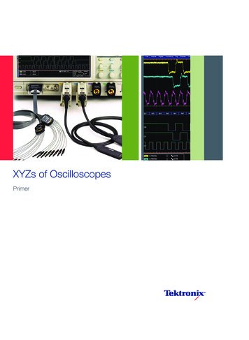
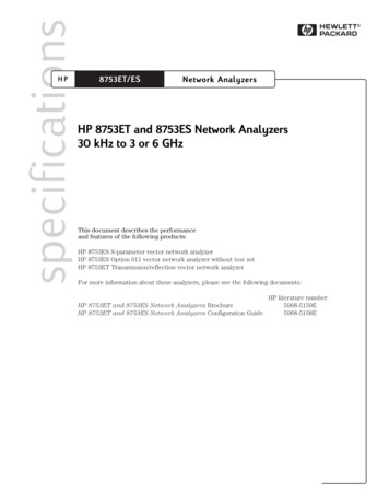
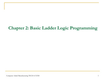
The XYZs of Logic AnalyzersIntroductionLike so many electronic test and measurement tools, alogic analyzer is a solution to a particular class of problems.It is a versatile tool that can help you with digital hardwaredebug, design verification and embedded software debug.The logic analyzer is an indispensable tool for engineers whodesign digital circuits.Logic analyzers are used for digitalmeasurements involving numerous signalsor challenging trigger requirements.We will first look at the digital oscilloscope and the resultingevolution of the logic analyzer. Then you will be shown whatcomprises a basic logic analyzer. With this basic knowledgeyou’ll then learn what capabilities of a logic analyzer areimportant and why they play a major part in choosing thecorrect tool for your particular application.Where It All BeganLogic analyzers evolved about the same time that the earliestcommercial microprocessors came to market. Engineersdesigning systems based on these new devices soon discovered that debugging microprocessor designs required moreinputs than oscilloscopes could offer.Logic analyzers, with their multiple inputs, solved this problem. These instruments have steadily increased both theiracquisition rates and channel counts to keep pace withrapid advancements in digital technology. The logic analyzeris a key tool for the development of digital systems.There are similarities and differences between oscilloscopesand logic analyzers. To better understand how the twoinstruments address their respective applications, it is usefulto take a comparative look at their individual capabilities.Figure 1. The oscilloscope reveals the details of signal amplitude, rise time, and otheranalog characteristics.The Digital OscilloscopeThe digital oscilloscope is the fundamental tool for generalpurpose signal viewing. Its high sample rate and bandwidthenables it to capture many data points over a span oftime, providing measurements of signal transitions (edges),transient events, and small time increments.While the oscilloscope is certainly capable of looking at thesame digital signals as a logic analyzer, most oscilloscopeusers are concerned with analog measurements such asrise- and fall-times, peak amplitudes, and the elapsed timebetween edges.A look at the waveform in Figure 1 illustrates the oscilloscope’s strengths. The waveform, though taken from a digitalcircuit, reveals the analog characteristics of the signal, allof which can have an effect on the signal’s ability to performits function. Here, the oscilloscope has captured detailsrevealing ringing, overshoot, rolloff in the rising edge, andother aberrations appearing periodically.www.tektronix.com/logic analyzers3
PrimerWhen Should I Use an Oscilloscope?When Should I Use a Logic Analyzer?If you need to measure the “analog” characteristics of afew signals at a time, the digital oscilloscope is the mosteffective solution. When you need to know specific signalamplitudes, power, current, or phase values, or edgemeasurements such as rise times, an oscilloscope is theright instrument.A logic analyzer is an excellent tool for verifying anddebugging digital designs. A logic analyzer verifies thatthe digital circuit is working and helps you troubleshootproblems that arise. The logic analyzer captures anddisplays many signals at once, and analyzes their timingrelationships. For debugging elusive, intermittent problems,some logic analyzers can detect glitches, as well assetup-and-hold time violations. During software/hardwareintegration, logic analyzers trace the execution of theembedded software and analyze the efficiency of theprogram's execution. Some logic analyzers correlatethe source code with specific hardware activities inyour design.Use a Digital Oscilloscope When YouNeed to:Characterize signal integrity (such as rise time,overshoot, and ringing) during verification of analogand digital devicesCharacterize signal stability (such as jitter andjitter spectrum) on up to four signals at onceMeasure signal edges and voltages to evaluate timingmargins such as setup/hold, propagation delayDetect transient faults such as glitches, runt pulses,metastable transitionsMeasure amplitude and timing parameters on afew signals at a timeWith the oscilloscope’s built-in tools such as cursors andautomated measurements, it’s easy to track down the signalintegrity problems that can impact your design. In addition,timing measurements such as propagation delay andsetup-and-hold time are natural candidates for an oscilloscope. And of course, there are many purely analog signals –such as the output of a microphone or digital-to-analogconverter – which must be viewed with an instrument thatrecords analog details.Oscilloscopes generally have up to four input channels.What happens when you need to measure five digital signalssimultaneously – or a digital system with a 32-bit data bus4www.tektronix.com/logic analyzersUse a Logic Analyzer When You Need to:Debug and verify digital system operationTrace and correlate many digital signals simultaneouslyDetect and analyze timing violations and transientson busesTrace embedded software executionand a 64-bit address bus? This points out the need for a toolwith many more inputs – the logic analyzer.The Logic AnalyzerThe logic analyzer has different capabilities than the oscilloscope. The most obvious difference between the twoinstruments is the number of channels (inputs). Typical digitaloscilloscopes have up to four signal inputs. Logic analyzerstypically have between 34 and 136 channels. Each channelinputs one digital signal. Some complex system designsrequire thousands of input channels. Appropriately-scaledlogic analyzers are available for those tasks as well.
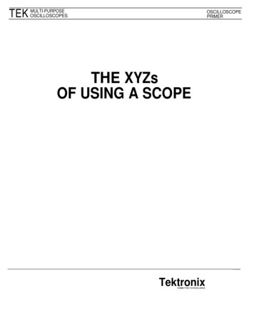
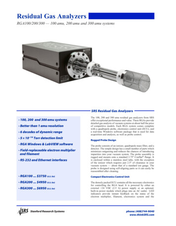
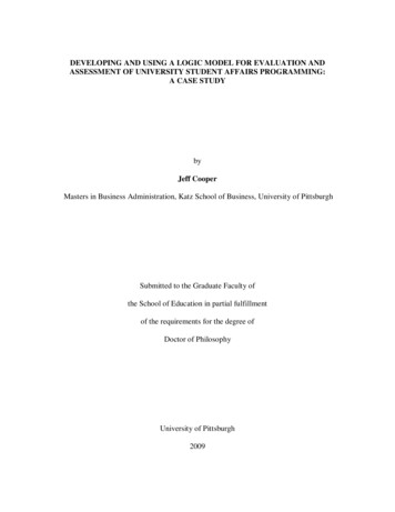
The XYZs of Logic AnalyzersLogic Analyzer OperationThe logic analyzer connects to, acquires, andanalyzes digital signals. There are four steps tousing a logic analyzer as shown in Figure 3.1 Connect2 SetupFigure 2. A logic Analyzer determines logic values relative to a threshold voltage level.A logic analyzer measures and analyzes signals differentlythan an oscilloscope. The logic analyzer doesn’t measureanalog details. Instead, it detects logic threshold levels.When you connect a logic analyzer to a digital circuit, you’reonly concerned with the logic state of the signal. A logicanalyzer looks for just two logic levels, as shown in Figure 2.When the input is above the threshold voltage (V) the level issaid to be “high” or “1;” conversely, the level below Vth is a“low” or “0.” When a logic analyzer samples input, it stores a“1” or a “0” depending on the level of the signal relative to thevoltage threshold.A logic analyzer’s waveform timing display is similar to thatof a timing diagram found in a data sheet or produced bya simulator. All of the signals are time-correlated, so thatsetup-and-hold time, pulse width, extraneous or missing datacan be viewed. In addition to their high channel count, logicanalyzers offer important features that support digital designverification and debugging. Among these are:Sophisticated triggering that lets you specify theconditions under which the logic analyzer acquires data3 Acquire4 Analyzestep 1step 2step 3step 4ConnectSetupAcquireAnalyzeFigure 3. Simplified logic analyzer operation.Connect to the System Under TestProbeThe large number of signals that can be captured at onetime by the logic analyzer is what sets it apart from theoscilloscope. The acquisition probes connect to the SUT.The probe’s internal comparator is where the input voltageis compared against the threshold voltage (Vth), and wherethe decision about the signal’s logic state (1 or 0) is made.The threshold value is set by the user, ranging from TTLlevels to, CMOS, ECL, and user-definable.High-density probes and adapters that simplifyconnection to the system under test (SUT)Analysis capabilities that translate captured data intoprocessor instructions and correlate it to source codewww.tektronix.com/logic analyzers5
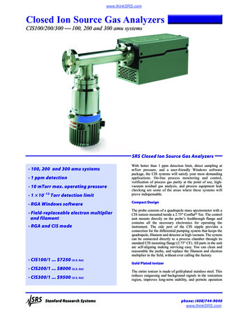
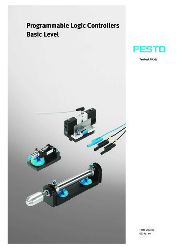
PrimerFigure 7. The impedance of the logic analyzer’s probe can affect signal rise times andmeasure timing relationships.Logic analyzer probes come in many physical forms:Figure 4. General purpose probe.General purpose probes with “flying lead sets” intendedfor point-by-point troubleshooting as shown in Figure 4.High-density, multi-channel probes that require dedicatedconnectors on the circuit board as shown in Figure 5.The probes are capable of acquiring high-quality signals,and have a minimal impact on the SUT.High-density compression probes that use a connectorless probe attach as shown in Figure 6. This type ofprobe is recommended for those applications thatrequire higher signal density or a connector-less probeattach mechanism for quick and reliable connections toyour system under test.Figure 5. High-density, multi-channel logic analyzer probe.The impedance of the logic analyzer’s probes (capacitance,resistance, and inductance) becomes part of the overall loadon the circuit being tested. All probes exhibit loading characteristics. The logic analyzer probe should introduce minimalloading on the SUT, and provide an accurate signal to thelogic analyzer.Probe capacitance tends to “roll off” the edges of signaltransitions, as shown in Figure 7. This roll off slows downthe edge transition by an amount of time represented as “tD”in Figure 7. Why is this important? Because a slower edgecrosses the logic threshold of the circuit later, introducingtiming errors in the SUT. This is a problem that becomesmore severe as clock rates increase.In high-speed systems, excessive probe capacitance canpotentially prevent the SUT from working! It is always criticalto choose a probe with the lowest possible total capacitance.It’s also important to note that probe clips and lead setsincrease capacitive loading on the circuits that they areconnected to. Use a properly compensated adapterwhenever possible.Figure 6. D-MaxTM connectorless analyzer probe.6www.tektronix.com/logic analyzers
The XYZs of Logic AnalyzersSet Up the Logic AnalyzerSet Up Clock ModesClock Mode SelectionLogic analyzers are designed to capture data from multi-pindevices and buses. The term “capture rate” refers to howoften the inputs are sampled. It is the same function as thetime base in an oscilloscope. Note that the terms “sample,”“acquire,” and “capture” are often used interchangeably whendescribing logic analyzer operations.There are two types of data acquisition, or clock modes:Timing acquisition captures signal timing information. In thismode, a clock internal to the logic analyzer is used to sampledata. The faster that data is sampled, the higher will be theresolution of the measurement. There is no fixed timingrelationship between the target device and the data acquiredby the logic analyzer. This acquisition mode is primarilyused when the timing relationship between SUT signals isof primary importance.State acquisition is used to acquire the “state” of the SUT.A signal from the SUT defines the sample point (when andhow often data will be acquired). The signal used to clockthe acquisition may be the system clock, a control signal onthe bus, or a signal that causes the SUT to change states.Data is sampled on the active edge and it represents thecondition of the SUT when the logic signals are stable. Thelogic analyzer samples when, and only when, the chosensignals are valid. What transpires between clock events isnot of interest here.What determines which type of acquisition is used? The wayyou want to look at your data. If you want to capture a long,contiguous record of timing details, then timing acquisition,the internal (or asynchronous) clock, is right for the job.Alternatively, you may want to acquire data exactly as theSUT sees it. In this case, you would choose state (synchronous) acquisition. With state acquisition, each successivestate of the SUT is displayed sequentially in a Listing window.The external clock signal used for state acquisition may beany relevant signal.Clock Mode Setup TipsThere are some general guidelines to follow in setting upa logic analyzer to acquire data:1. Timing (asynchronous) acquisition: The sampleclock rate plays an important role in determining theresolution of the acquisition. The timing accuracyof any measurement will always be one sampleinterval plus other errors specified by the manufacture.As an example, when the sample clock rate is 2 ns,a new data sample is stored into the acquisitionmemory every 2 ns. Data that changes after thatsample clock is not captured until the next sampleclock. Because the exact time when the datachanged during this 2 ns period cannot be known,the net resolution is 2 ns.2. State (synchronous) acquisition: When acquiringstate information, the logic analyzer, like any synchronous device, must have stable data present at theinputs prior to and after the sample clock to assurethat the correct data is captured.Set Up TriggeringTriggering is another capability that differentiates the logicanalyzer from an oscilloscope. Oscilloscopes have triggers,but they have relatively limited ability to respond to binaryconditions. In contrast, a variety of logical (Boolean) conditions can be evaluated to determine when the logic analyzertriggers. The purpose of the trigger is to select which data iscaptured by the logic analyzer. The logic analyzer can trackSUT logic states and trigger when a user-defined eventoccurs in the SUT.When discussing logic analyzers, it’s important to understandthe term “event.” It has several meanings. It may be a simpletransition, intentional or otherwise, on a single signal line. Ifyou are looking for a glitch, then that is the “event” of interest.An event may be the moment when a particular signal suchas Increment or Enable becomes valid. Or an event may bethe defined logical condition that results from a combinationwww.tektronix.com/logic analyzers7
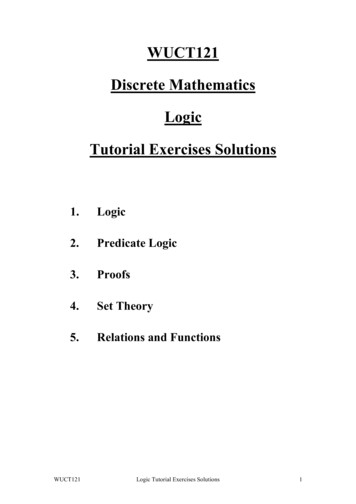
PrimerThe Confusion of Double ProbesThe Simplicity of Single ure 8. Double-probing requires two probes on each test point, decreasing thequality of the measurement.Figure 9. Simultaneous probing provides state and timing acquisition through thesame probe, for a simpler, cleaner measurement environment.of signal transitions across a whole bus. Note that in allinstances, though, the event is something that appears whensignals change from one cycle to the next.Acquire State and Timing DataMany conditions can be used to trigger a logic analyzer.During hardware and software debug (system integration),it’s helpful to have correlated state and timing information.For example, the logic analyzer can recognize a specificbinary value on a bus or counter output. Other triggeringchoices include:Words: specific logic patterns defined in binary,hexadecimal, etc.Ranges: events that occur between a low and high valueCounter: the user-programmed number of eventstracked by a counterSignal: an external signal such as a system resetGlitches: pulses that occur between acquisitionsTimer: the elapsed time between two events or theduration of a single event, tracked by a timerAnalog: use an oscilloscope to trigger on an analogcharacteristic and to cross-trigger the logic analyzerWith all these trigger conditions available, it is possible totrack down system errors using a broad search for statefailures, then refining the search with increasingly explicittriggering conditions.8www.tektronix.com/logic analyzersSimultaneous State and TimingA problem may initially be detected as an invalid state on thebus. This may be caused by a problem such as a setup andhold timing violation. If the logic analyzer cannot capture bothtiming and state data simultaneously, isolating the problembecomes difficult and time-consuming.Some logic analyzers require connecting a separate timingprobe to acquire the timing information and use separateacquisition hardware. These instruments require you toconnect two types of probes to the SUT at once, as shownin Figure 8. One probe connects the SUT to a Timing module,while a second probe connects the same test points to aState module. This is known as “double-probing.” It’s anarrangement that can compromise the impedance environment of your signals. Using two probes at once will loaddown the signal, degrading the SUT’s rise and fall times,amplitude, and noise performance. Note that Figure 8 isa simplified illustration showing only a few representativeconnections. In an actual measurement, there might be four,eight, or more multi-conductor cables attached.
The XYZs of Logic AnalyzersIt is best to acquire timing and state data simultaneously,through the same probe at the same time, as shown inFigure 9. One connection, one setup, and one acquisitionprovide both timing and state data. This simplifies themechanical connection of the probes and reduces problems.With simultaneous timing and state acquisition, the logicanalyzer captures all the information needed to supportboth timing and state analysis. There is no second step,and therefore less chance of errors and mechanical damagethat can occur with double probing. The single probe’s effecton the circuit is low
inputs than oscilloscopes could offer. Logic analyzers, with their multiple inputs, solved this prob-lem. These instruments have steadily increased both their acquisition rates and channel counts to keep pace with rapid advancements in digit