Transcription
The XYZsof Logic Analyzers
The XYZs of Logic AnalyzersPrimerTable of ----------------------4 - 5Where It All Began4Digital Oscilloscope4The Logic Analyzer5Logic Analyzer Operation ------------------------------------6 -136Connect to the System Under TestProbe6Set Up77Set Up Clock ModesSet Up Triggering8Acquisition9Simultaneous State and Timing9Real-time Acquisition Memory10Integrated Analog-Digital Troubleshooting Tools11Analysis and Display12Waveform Display12Listing Display1314Automated MeasurementsPerformance Terms and Considerations --------------------15 -16Timing Acquisition Rate15State Acquisition Rate15MagniVu Acquisition Rate15Record Length1516Channel Count and ModularityTriggering16Probing16Logic Analyzer Measurement Examples --------------------16-20Making General Purpose Timing Measurements17Detecting and Displaying Intermittent Glitches18Capturing Setup or Hold Violations19Applying Transitional Storage to Maximize20Usable Record LengthLogic Analyzer Application Examples ----------------------21-26FPGA21Memory23Signal Integrity24Serial Data Compliance, Validation and Debug25Summary ----26Glossary ----------27www.tektronix.com/logic analyzers3
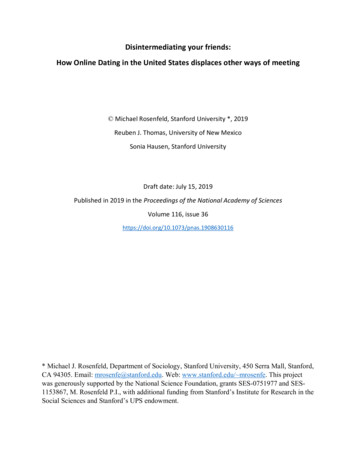
The XYZs of Logic AnalyzersPrimerIntroductionLike so many electronic test and measurement tools, alogic analyzer is a solution to a particular class of problems.It is a versatile tool that can help you with digital hardwaredebug, design verification and embedded software debug.The logic analyzer is an indispensable tool for engineerswho design digital circuits.Logic analyzers are used for digital measurements involvingnumerous signals or challenging trigger requirements.We will first look at the digital oscilloscope and the resultingevolution of the logic analyzer. Then you will be shown whatcomprises a basic logic analyzer. With this basic knowledgeyou’ll then learn what capabilities of a logic analyzer areimportant and why they play a major part in choosing thecorrect tool for your particular application.Where It All BeganLogic analyzers evolved about the same time that theearliest commercial microprocessors came to market.Engineers designing systems based on these new devicessoon discovered that debugging microprocessor designsrequired more inputs than oscilloscopes could offer.Logic analyzers, with their multiple inputs, solved thisproblem. These instruments have steadily increased boththeir acquisition rates and channel counts to keep pacewith rapid advancements in digital technology. The logicanalyzer is a key tool for the development of digital systems.There are similarities and differences between oscilloscopesand logic analyzers. To better understand how the twoinstruments address their respective applications, it is usefulto take a comparative look at their individual capabilities.The Digital OscilloscopeThe digital oscilloscope is the fundamental tool for generalpurpose signal viewing. Its high sample rate and bandwidthenables it to capture many data points over a span oftime, providing measurements of signal transitions (edges),transient events, and small time increments.4www.tektronix.com/logic analyzersFigure 1. The oscilloscope reveals the details of signal amplitude,rise time, and other analog characteristics.While the oscilloscope is certainly capable of looking at thesame digital signals as a logic analyzer, most oscilloscopeusers are concerned with analog measurements such asrise- and fall-times, peak amplitudes, and the elapsed timebetween edges.A look at the waveform in Figure 1 illustrates theoscilloscope’s strengths. The waveform, though taken froma digital circuit, reveals the analog characteristics of thesignal, all of which can have an effect on the signal’s abilityto perform its function. Here, the oscilloscope has captureddetails revealing ringing, overshoot, rolloff in the rising edge,and other aberrations appearing periodically.With the oscilloscope’s built-in tools such as cursors andautomated measurements, it’s easy to track down the signalintegrity problems that can impact your design. In addition,timing measurements such as propagation delay and setupand-hold time are natural candidates for an oscilloscope.And of course, there are many purely analog signals – suchas the output of a microphone or digital-to-analog converter– which must be viewed with an instrument that recordsanalog details.Oscilloscopes generally have up to four input channels.What happens when you need to measure five digitalsignals simultaneously – or a digital system with a 32-bitdata bus and a 64-bit address bus? This points out theneed for a tool with many more inputs – the logic analyzer.
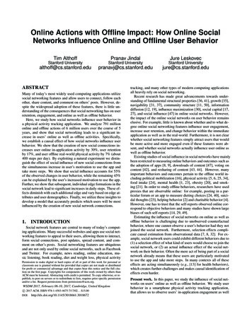
The XYZs of Logic AnalyzersPrimerWhen Should I Use an Oscilloscope?When Should I Use a Logic Analyzer?If you need to measure the “analog” characteristics ofa few signals at a time, the digital oscilloscope is themost effective solution. When you need to knowspecific signal amplitudes, power, current, or phasevalues, or edge measurements such as rise times, anoscilloscope is the right instrument.A logic analyzer is an excellent tool for verifying anddebugging digital designs. A logic analyzer verifies thatthe digital circuit is working and helps you troubleshootproblems that arise. The logic analyzer captures anddisplays many signals at once, and analyzes theirtiming relationships. For debugging elusive, intermittentproblems, some logic analyzers can detect glitches,as well as setup-and-hold time violations. Duringsoftware/hardware integration, logic analyzers tracethe execution of the embedded software and analyzethe efficiency of the program's execution. Some logicanalyzers correlate the source code with specifichardware activities in your design.Use a Digital Oscilloscope When YouNeed to:Characterize signal integrity (such as rise time,overshoot, and ringing) during verification of analogand digital devicesCharacterize signal stability (such as jitter andjitter spectrum) on up to four signals at onceMeasure signal edges and voltages to evaluatetiming margins such as setup/hold, propagationdelayDetect transient faults such as glitches, runt pulses,metastable transitionsMeasure amplitude and timing parameters on afew signals at a timeUse a Logic Analyzer When YouNeed to:Debug and verify digital system operationTrace and correlate many digital signals simultaneouslyDetect and analyze timing violations and transientson busesTrace embedded software executionThe Logic AnalyzerThe logic analyzer has different capabilities than theoscilloscope. The most obvious difference between thetwo instruments is the number of channels (inputs). Typicaldigital oscilloscopes have up to four signal inputs. Logicanalyzers have between 34 and 136 channels. Eachchannel inputs one digital signal. Some complex systemdesigns require thousands of input channels. Appropriatelyscaled logic analyzers are available for those tasks as well.A logic analyzer measures and analyzes signals differentlythan an oscilloscope. The logic analyzer doesn’t measureanalog details. Instead, it detects logic threshold levels.When you connect a logic analyzer to a digital circuit,you’re only concerned with the logic state of the signal.A logic analyzer looks for just two logic levels, as shownin Figure 2.Figure 2. A logic Analyzer determines logic values relative to athreshold voltage level.www.tektronix.com/logic analyzers5
The XYZs of Logic AnalyzersPrimerWhen the input is above the threshold voltage (V) the levelis said to be “high” or “1;” conversely, the level below Vthis a “low” or “0.” When a logic analyzer samples input, itstores a “1” or a “0” depending on the level of the signalrelative to the voltage threshold.A logic analyzer’s waveform timing display is similar to thatof a timing diagram found in a data sheet or produced bya simulator. All of the signals are time-correlated, so thatsetup-and-hold time, pulse width, extraneous or missingdata can be viewed. In addition to their high channel count,logic analyzers offer important features that support digitaldesign verification and debugging. Among these are:Figure 4. General purpose probe.Sophisticated triggering that lets you specify theconditions under which the logic analyzer acquires dataHigh-density probes and adapters that simplifyconnection to the system under test (SUT)Analysis capabilities that translate captured data intoprocessor instructions and correlate it to source codeLogic Analyzer OperationThe logic analyzer connects to, acquires, and analyzesdigital signals. There are four steps to using a logic analyzeras shown in figure 3.1 ConnectFigure 5. High-density, multi-channel logic analyzer probe.2 Setup3 AcquireConnect to the System Under Test4 Analyze and DisplayProbestep 1step 2step 3step 4ConnectSetupAcquireAnalyzeandDisplayFigure 3. Simplified logic analyzer operation.6www.tektronix.com/logic analyzersThe large number of signals that can be captured at onetime by the logic analyzer is what sets it apart from theoscilloscope. The acquisition probes connect to the SUT.The probe’s internal comparator is where the input voltageis compared against the threshold voltage (Vth), and wherethe decision about the signal’s logic state (1 or 0)is made. The threshold value is set by the user, rangingfrom TTL levels to, CMOS, ECL, and user-definable.
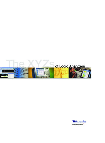
The XYZs of Logic AnalyzersPrimerFigure 7. The impedance of the logic analyzer’s probe can affectsignal rise times and measure timing relationships.In high-speed systems, excessive probe capacitance canpotentially prevent the SUT from working! It is alwayscritical to choose a probe with the lowest possible totalcapacitance.Figure 6. D-MaxTM connectorless analyzer probe.Logic analyzer probes come in many physical forms:General purpose probes with “flying lead sets” intendedfor point-by-point troubleshooting as shown in figure 4.High-density, multi-channel probes that require dedicatedconnectors on the circuit board as shown in Figure 5.The probes are capable of acquiring high-quality signals,and have a minimal impact on the SUT.High-density compression probes that use a connectorless probe attach as shown in Figure 6. This type ofprobe is recommended for those applications thatrequire higher signal density or a connector-less probeattach mechanism for quick and reliable connections toyour system under test.The impedance of the logic analyzer’s probes (capacitance,resistance, and inductance) becomes part of the overallload on the circuit being tested. All probes exhibit loadingcharacteristics. The logic analyzer probe should introduceminimal loading on the SUT, and provide an accurate signalto the logic analyzer.Probe capacitance tends to “roll off” the edges of signaltransitions, as shown in Figure 7. This roll off slows downthe edge transition by an amount of time representedas “t ” in Figure 7. Why is this important? Because aslower edge crosses the logic threshold of the circuit later,introducing timing errors in the SUT. This is a problemthat becomes more severe as clock rates increase.It’s also important to note that probe clips and lead setsincrease capacitive loading on the circuits that theyare connected to. Use a properly compensated adapterwhenever possible.Set UpSet Up Clock ModesClock Mode SelectionLogic analyzers are designed to capture data from multi-pindevices and buses. The term “capture rate” refers to howoften the inputs are sampled. It is the same function as thetime base in an oscilloscope. Note that the terms “sample,”“acquire,” and “capture” are often used interchangeablywhen describing logic analyzer operations.There are two types of data acquisition, or clock modes:Timing acquisition captures signal timing information. Inthis mode, a clock internal to the logic analyzer is used tosample data. The faster that data is sampled, the higherwill be the resolution of the measurement. There is no fixedtiming relationship between the target device and the dataacquired by the logic analyzer. This acquisition mode isprimarily used when the timing relationship between SUTsignals is of primary importance.State acquisition is used to acquire the “state” of the SUT.A signal from the SUT defines the sample point (when andhow often data will be acquired). The signal used to clockthe acquisition may be the system clock, a control signal onwww.tektronix.com/logic analyzers7
The XYZs of Logic AnalyzersPrimerthe bus, or a signal that causes the SUT to change states.Data is sampled on the active edge and it represents thecondition of the SUT when the logic signals are stable. Thelogic analyzer samples when, and only when, the chosensignals are valid. What transpires between clock events isnot of interest here.What determines which type of acquisition is used? Theway you want to look at your data. If you want to capturea long, contiguous record of timing details, then timingacquisition, the internal (or asynchronous) clock, is rightfor the job.Alternatively, you may want to acquire data exactly asthe SUT sees it. In this case, you would choose state(synchronous) acquisition. With state acquisition, eachsuccessive state of the SUT is displayed sequentiallyin a Listing window. The external clock signal used forstate acquisition may be any relevant signal.Set Up TriggeringTriggering is another capability that differentiates the logicanalyzer from an oscilloscope. Oscilloscopes have triggers,but they have relatively limited ability to respond to binaryconditions. In contrast, a variety of logical (Boolean)conditions can be evaluated to determine when the logicanalyzer triggers. The purpose of the trigger is to selectwhich data is captured by the logic analyzer. The logicanalyzer can track SUT logic states and trigger when auser-defined event occurs in the SUT.When discussing logic analyzers, it’s important tounderstand the term “event.” It has several meanings. Itmay be a simple transition, intentional or otherwise, ona single signal line. If you are looking for a glitch, then thatis the “event” of interest. An event may be the momentwhen a particular signal such as Increment or Enablebecomes valid. Or an event may be the defined logicalcondition that results from a combination of signaltransitions across a whole bus. Note that in all instances,though, the event is something that appears when signalschange from one cycle to the next.Clock Mode Setup TipsThere are some general guidelines to follow in settingup a logic analyzer to acquire data:1. Timing (asynchronous) acquisition: The sampleclock rate plays an important role in determiningthe resolution of the acquisition. The timingaccuracy of any measurement will always be onesample interval plus other errors specified by themanufacture. As an example, when the sampleclock rate is 2 ns, a new data sample is storedinto the acquisition memory every 2 ns. Data thatchanges after that sample clock is not captureduntil the next sample clock. Because the exacttime when the data changed during this 2 ns periodcannot be known, the net resolution is 2 ns.2. State (synchronous) acquisition: When acquiringstate information, the logic analyzer, like anysynchronous device, must have stable data presentat the inputs prior to and after the sample clockto assure that the correct data is captured.Many conditions can be used to trigger a logic analyzer.For example, the logic analyzer can recognize a specificbinary value on a bus or counter output. Other triggeringchoices include:Words: specific logic patterns defined in binary,hexadecimal, etc.Ranges: events that occur between a low andhigh valueCounter: the user-programmed number of eventstracked by a counterSignal: an external signal such as a system resetGlitches: pulses that occur between acquisitionsTimer: the elapsed time between two events or theduration of a single event, tracked by a timerAnalog: use an oscilloscope to trigger on an analogcharacteristic and to cross-trigger the logic analyzer8www.tektronix.com/logic analyzers
The XYZs of Logic AnalyzersPrimerThe Simplicity of Single ProbesThe Confusion of Double ure 8. Double-probing requires two probes on each test point,decreasing the quality of the measurement.With all these trigger conditions available, it is possible totrack down system errors using a broad search for statefailures, then refining the search with increasingly explicittriggering conditions.AcquisitionSimultaneous State and TimingDuring hardware and software debug (system integration),it’s helpful to have correlated state and timing information.A problem may initially be detected as an invalid stateon the bus. This may be caused by a problem such as asetup and hold timing violation. If the logic analyzer cannotcapture both timing and state data simultaneously, isolatingthe problem becomes difficult and time-consuming.Some logic analyzers require connecting a separate timingprobe to acquire the timing information and use separateacquisition hardware. These instruments require you toconnect two types of probes to the SUT at once, as shownin Figure 8. One probe connects the SUT to a Timingmodule, while a second probe connects the same testpoints to a State module. This is known as “doubleprobing.” It’s an arrangement that can compromise theimpedance environment of your signals. Using two probesFigure 9. Simultaneous probing provides state and timingacquisition through the same probe, for a simpler,cleaner measurement environment.at once will load down the signal, degrading the SUT’srise and fall times, amplitude, and noise performance. Notethat Figure 8 is a simplified illustration showing only a fewrepresentative connections. In an actual measurement,there might be four, eight, or more multi-conductor cablesattached.It is best to acquire timing and state data simultaneously,through the same probe at the same time, as shown inFigure 9. One connection, one setup, and one acquisitionprovide both timing and state data. This simplifies themechanical connection of the probes and reducesproblems.With simultaneous timing and state acquisition, the logicanalyzer captures all the information needed to supportboth timing and state analysis. There is no second step,and therefore less chance of errors and mechanicaldamage that can occur with double probing. The singleprobe’s effect on the circuit is lower, ensuring moreaccurate measurements and less impact on the circuit’soperation.The higher the timing resolution, the more details you cansee and trigger on in your design, increasing your chanceof finding problems.www.tektronix.com/logic analyzers9
The XYZs of Logic AnalyzersPrimerReal-time Acquisition MemoryThe logic analyzer’s probing, triggering, and clockingsystems exist to deliver data to the real-time acquisitionmemory. This memory is the heart of the instrument – thedestination for all of the sampled data from the SUT, andthe source for all of the instrument’s analysis and display.Logic analyzers have memory capable of storing data at theinstrument’s sample rate. This memory can be envisionedas a matrix having channel width and memory depth, asshown in Figure 10.The instrument accumulates a record of all signal activityuntil a trigger event or the user tells it to stop. The resultis an acquisition – essentially a multi-channel waveformdisplay that lets you view the interaction of all the signalsyou’ve acquired, with a very high degree of timing precision.Channel count and memory depth are key factors inchoosing a logic analyzer. Following are some tips to helpyou determine your channel count and memory depth:How many signals do you need to capture andanalyze?Your logic analyzer’s channel count maps directly to thenumber of signals you want to capture. Digital systembuses come in various widths, and there is often a needto probe other signals (clocks, enables, etc.) at the sameti
Oscilloscopes generally have up to four input channels. What happens when you need to measure five digital signals simultaneously – or a digital system with a 32-bit data bus and a 64-bit address bus? This points out the need for a tool with many more inputs – the logic analyzer. Fig