Transcription
MULTI-PURPOSETEK OSCILLOSCOPESOSCILLOSCOPEPRIMERTHE XYZsOF USING A SCOPETektronixCOMMITTED TO EXCELLENCE
CONTENTSINTRODUCTION1PART I. Scopes, Controls, & Probes2PART II. Making Measurements19Chapter 6. WAVEFORMS19Chapter 1. THE DISPLAY SYSTEMBeam FinderIntensityFocusTrace RotationUsing the Display Controls444455Chapter 7. SAFETY22Chapter 8. GETTING STARTEDCompensating the ProbeChecking the ControlsHandling Probe22222222Chapter 2. THE VERTICAL SYSTEMVertical PositionInput CouplingVertical SensitivityVariable VOLTS/DIVChannel 2 InversionVertical Operating ModesAlternate Sweep SeparationUsing the Vertical Controls666677788Chapter 9. MEASUREMENT TECHNIQUESThe Foundations: Amplitude and Time MeasurementsFrequency and Other Derived MeasurementsPulse MeasurementsPhase MeasurementsX-Y MeasurementsUsing the Z-AxisUsing TV TriggeringDelayed Sweep MeasurementsSingle Time Base ScopesDual Time Base Scopes2424252526262728282829Chapter 10. SCOPE PERFORMANCESquare Wave Response and High Frequency ResponseInstrument Rise Time and Measured Rise TimesBandwidth and Rise Time32323233Chapter 3. THE HORIZONTAL SYSTEMHorizontal PositionHorizontal Operating ModesSweep SpeedsVariable SEC/DIVHorizontal MagnificationThe DELAY TIME and MULTIPLIER ControlsThe B DELAY TIME POSITION ControlUsing the Horizontal Controls101010101111111111Chapter 4. THE TRIGGER SYSTEMTrigger Level and SlopeVariable Trigger HoldoffTrigger SourcesTrigger Operating ModesTrigger CouplingUsing the Trigger Controls12131414151616Chapter 5. ALL ABOUT PROBESCircuit LoadingMeasurement System BandwidthProbe TypesPicking a Probe1717171818INDEXREPRODUCED BY PERMISSIONOF THE COPYRIGHT OWNER:TEKTRONIX, INC.(Letter dated: 11/20/85,Gaithersbucp, Md.)Copyright @ 1981, Tektronix, Inc All rights reserved34
INTRODUCTIONIf you watch an electrical engineer tackling a tough designproject, or a service engineertroubleshooting a stubbornproblem, you’ll see them grab ascope, fit probes or cables, andstart turning knobs and settingswitches without ever seemingto glance at the front panel. Tothese experienced users, theoscilloscope is their most important tool but their minds are focused on solving the problem,not on using the scope.Making oscilloscope measurements is second nature tothem. It can be for you too, butbefore you can duplicate theease with which they use ascope, you will need to concentrate on learning about thescope itself: both how it worksand how to make it work for you.The purpose of this primer isto help you learn enough aboutoscilloscopes and oscilloscopemeasurements that you will beable to use these measurementtools quickly, easily, and accurately.The text is divided into twoparts:The first four chapters of Part Idescribe the functional parts ofscopes and the controls associated with those parts. Then achapter on probes concludesthe section.Part II allows you to build onthe knowledge and experienceyou gained from Part I. The signals you’ll see on the screen ofan oscilloscope are identified bywaveshape and the terms forparts of waveforms are discussed. The next two chapterscover safety topics and instrument set-up procedures.Then Chapter 9 describesmeasurement techniques.Exercises there let you practicesome basic measurements, andseveral examples of advancedtechniques that can help youmake more accurate and convenient measurements are alsoincluded. The last chapter in thisprimer discusses oscilloscopeperformance and its effects onyour measurements.Having a scope in front of youwhile working through the chapters is the best way to both learnand practice applying your newknowledge. While the fundamentals will apply to almost anyscope, the exercises and illustrations use two specific instruments: the Tektronix 2213 and2215 Portable Oscilloscopes.The 2213 is a dual-channel, 60MHz portable designed as aneasy-to-use, lightweight,general-purpose oscilloscope.The 2215 is a dual time baseoscilloscope with more featuresand capabilities; it’s included soyou will understand dual timebase scopes and appreciatethe additional measurementcapabilities they offer.If you have comments orquestions about the material inthis primer, please don’t hesitateto write.Chet HeybergerPortable Scopes TechnicalCommunications ManagerMarshall E. Pryor2200 Series Product LineMarketing ManagerPrimer - DS 391199Tektronix, Inc.PO. Box 500Beaverton, OR 97077
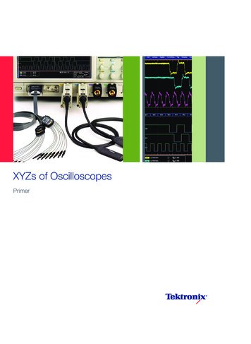
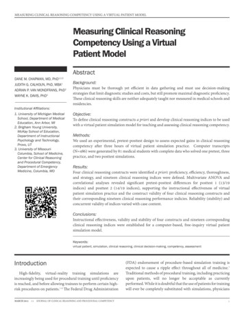
PART I. SCOPES, CONTROLS, & PROBESYou can measure almost anything with the two-dimensionalgraph drawn by an oscilloscope. In most applications thescope shows you a graph ofvoltage (on the vertical axis)versus time (on the horizontalaxis). This general-purposedisplay presents far more information than is available fromother test and measurement instruments like frequency counters or multimeters. For example, with a scope you can findout how much of a signal is direct, how much is alternating,how much is noise (and whetheror not the noise is changing withtime), and what the frequency ofthe signal is as well. Using ascope lets you see everything atonce rather than requiring you tomake many separate tests.Most electrical signals can beeasily connected to the scopewith either probes or cables.And then for measuring nonelectrical phenomena, transducers are available. Transducers change one kind of energyinto another. Speakers andmicrophones are two examples;the first changes electrical energy to sound waves and thesecond converts sound intoelectricity. Other typical transducers can transform temperature, mechanical stress, pressure, light, or heat into electricalsignals. You can see that giventhe proper transducer, your testand measurement capabilitiesare almost endless with an oscilloscope.Making measurements iseasier if you understand thebasics of how a scope works.You can think of the instrument interms of the functional blocks illustrated in Figure 1: vertical systern, trigger system, horizontalsystem, and display system.m%-VfZgWALSECTIONFigure 1.THE BASIC OSCILLOSCOPE in its most general form has only four functional blocks:vertical, horizontal, trigger, and display systems (and sometimes, sections). Thedisplay system is also sometimes called the CRT (for cathode-ray tube) section.Each is named for its function.The vertical system controls thevertical axis of the graph; anytime the electron beam thatdraws the graph moves up ordown, it does so under control ofthe vertical system. The horizontal system controls the left toright movement of the beam.The trigger system determineswhen the oscilloscope draws; ittriggers the beginning of thehorizontal sweep across thescreen. And the display systemcontains the cathode-ray tube,where the graph is drawn.This part of the primer is divided into chapters for each ofthose functional blocks. Thecontrols for each block arenamed first, and you can use atwo-page, fold-out illustration ofa Tektronix 2213 front panel atthe back of the primer to locatethem on your scope. Next thecontrols and their functions aredescribed, and at the end ofeach chapter there are handson exercises using those controls.The last chapter in this sectiondescribes probes. When youfinish reading these five chapters, you’ll be ready to make fastand accurate oscilloscopemeasurements.But before you turn on yourscope, remember that youshould always be careful whenyou work with electrical equipment. Observe a// safety precautions in your test and measurement operations. Alwaysplug the power cord of thescope into a properly-wired receptacle before connectingyour probes or turning on thescope; use the proper powercord for your scope, and useonly the correct fuse. Don’t remove the covers and panels ofyour scope.Now fold out the front panelillustration at the back of theprimer, so that it is visible as youread. Use the foldout and followExercise 1 to initialize (set instandard positions) the scopecontrols. These standard settings are necessary so that asyou follow the directions onthese pages, you’ll see thesame thing on your scope’s CRTas is pictured or described here.
PART IExercise 1. INITIALIZING THE SCOPEUse the foldout figure and callouts to locate the controls mentioned here.1. DISPLAY SYSTEM CONTROLS: Set the AUTO INTENSITY control at midrange (abouthalfway from either stop). Turnthe AUTO FOCUS knob completely clockwise.2. VERTICAL SYSTEM CONTROLS: Turn the channel 7 POSITION control completelycounterclockwise. Make surethe lefthand VERTICAL MODEswitch is set to CH 7. Move bothchannel VOLTS/D/V switches tothe least sensitive setting byrotating them completely counterclockwise. And make surethe center, red VAR controls arelocked in their detents at the extreme clockwise position. Inputcoupling switches should be setto GND.3. HORIZONTAL SYSTEMCONTROLS: Make sure theHORIZONTAL MODE switch isset to NO DLY for no delay. (Ifyou ’re using a 2275, move theswitch to the A sweep position.)Rotate the SEC/DIV switch to0.5 millisecond (0.5 ms). Makesure the red VAR (variable)switch in the center of the knobis in its detent position by moving it completely clockwise. Andpush in on the VAR switch tomake sure the scope is not in amagnified mode.4. TRIGGER SYSTEM CONTROLS: Make sure the VARHOLDOFF controlis set to its fullcounterclockwise position. Setthe trigger MODE switch (2275:A TRIGGER MODE) on AUTO.And move the trigger SOURCEswitch (A SOURCE on a 2275) to/NT (internal) and the INT selection switch (A&B INT on a 2275)to CH 7.After following the steps inExercise 7, you should plug yourscope into a properly-groundedoutlet and turn it on. With a Tektronix 2200 scope, there ’s noneed to change the scope'spower supply settings to matchthe local power line; the scopesoperate on main power from 90to 250 Vat at 48 to 62 Hz.
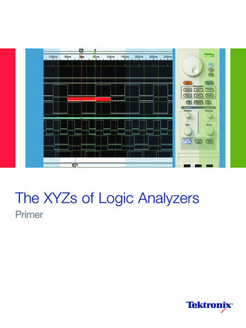
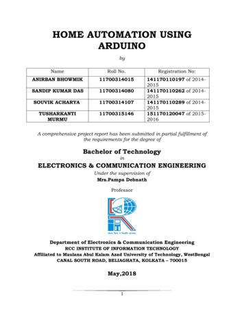
CHAPTER 1. THE DISPLAY SYSTEMThe oscilloscope draws a graphby moving an electron beamacross a phosphor coating onthe inside of the CRT (cathoderay tube). The result is a glow fora short time afterward tracingthe path of the beam. A grid oflines etched on the inside of thefaceplate serves as the reference for your measurements;this is the graticule shown inFigure 2.CENTERI-GWTICUELINESFigure 2.THE GRATICLJLE is a grid of lines typically etched or silk-screened on the inside ofthe CRT faceplate. Putting the graticule inside-on the same plane as the tracedrawn by the electron beam. and not on the outside of the glass - eliminatesmeasurement inaccuracies called parallax errors. Parallax errors occur when thetrace and the graticule are on different planes and the observer is shifted slightly fromthe direct line of sight. Though different sized CRT’s may be used, graticules areusually laid out in an 8 x 10 pattern. Each of the eight vertical and ten horizontal linesblock off major divisions (or just divisions) of the screen. The labeling on scopecontrols always refers to major divisions. The tick marks on the center graticule linesrepresent minor divisions or subdivisions. Since rise time measurements are verycommon. 2200 Series scope graticules include rise time measurement markings:dashed lines for 0 and 100% points, and labeled graticule lines for 10 and 90%Common controls for displaysystems include intensity andfocus; less often, you will alsofind beam finder and trace rotation controls. On a Tektronix2200 Series instrument they areall present, grouped next to andon the right of the CRT At the topof the group is the intensity control (labeled AUTO INTENSITYon a 2200 because these instruments automatically maintain the trace intensity once it isset). The TRACE ROTATION adjustment is under that, and thenthe beam finder (BEAM FIND).Under the probe adjustmentjack is the focus control (labeledAUTO FOCUS because it’s alsoautomatic). The functions ofthese controls are describedbelow and their positions on theTektronix 2213 Portable Oscilloscope are illustrated by the foldout illustration at the rear of thebooklet.Beam FinderThe beam finder is a convenience control that allows you tolocate the electron beam anytime it’s off-screen. When youpush the BEAM FIND button,you reduce the vertical andhorizontal deflection voltages(more about deflection voltageslater) and over-ride the intensitycontrol so that the beam alwaysappears within the 8 x 10centimeter screen. When yousee which quadrant of thescreen the beam appears in,you’ll know which directions toturn the horizontal and verticalPOSITION controls to repositionthe trace on the screen for normal operations.IntensityAn intensity control adjusts thebrightness of the trace. It’snecessary because you use ascope in different ambient lightconditions and with many kindsof signals. For instance, onsquare waves you might want tochange the trace brightness tolook at different parts of thewaveform because the slowerhorizontal components will always appear brighter than thefaster vertical components.Intensity controls are also useful because the intensity of atrace is a function of both howbright the beam is and how longit’s on-screen. As you select different sweep speeds (a sweepis one movement of the electronbeam across the scope screen)with the SEC/DIV switch, thebeam ON and OFF timeschange and the beam has moreor less time to excite the phosphorOn most scopes, you have toturn the intensity up or down torestore the initial brightness. Onthe 2200 Series scopes, however the automatic intensity circuit compensates for changesin sweep speed from 0.5 milliseconds (0.5 ms) to 0.5 microseconds (0.5 ,us). W ithin thisrange, the automatic circuitmaintains the same trace intensity you initially set with theAUTO INTENSITY control.FocusThe scope’s electron beam isfocused on the CRT faceplateby an electrical grid within thetube. The focus control adjuststhat grid for optimum tracefocus. On a 2200 scope, theAUTO FOCUS circuit maintainsyour focus settings over mostintensity settings (0.5 ms to0.5 us).
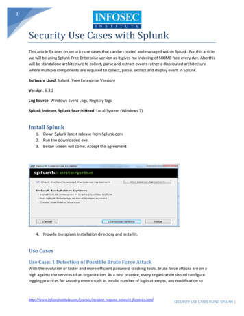
PART ITrace RotationAnother display control you’llfind on the front panel of a 2200Series instrument is TRACE ROTATION. The trace rotation adjustment allows you to electrically align the horizontal deflection of the trace with the fixedgraticule. To avoid accidentalmisalignments when the scopeis in use, the control is recessedand must be adjusted with asmall screwdriver.If this seems like a calibrationitem that should be adjustedonce and then forgotten, you’reright; that’s true for most oscilloscope applications. But theearth’s magnetic field affectsthe trace alignment and when ascope is used in many differentpositions - as a service scopewill be - it’s very handy to havea front panel trace rotation adjustment.Using the Display ControlsThe display system and its controls are shown as functionalblocks in Figure 3. Use Exercise2 to review the display controls.Figure 3.THE DISPLAY SYSTEM of your scopeconsists of the cathode-ray tube and itscontrols. To draw the graph of your measurements, the vertical system of thescope supplies the Y, or vertical, coordinates and the horizontal systemsupplies the X coordinates. There is alsoa Z dimension in a scope; it determineswhether or not the electron beam isturned on, and how bright it is when it’son.l-x---/Exercise 2. THE DISPLAY SYSTEM CONTROLSIn Exercise 7 you initialized yourscope and turned on the power.Now you can find the displaysystem controls labeled on thefoldout front panel illustrationand use them as you followthese instructions.1. BEAM FIND: Locate theposition of the electron beam bypushing and holding in theBEAM FIND button; then use thechannel 7 vertical POSITIONknob to position the trace on thecenter horizontal graticule line.Keep BEAM FIND depressedand use the horizontal POSITION control to center the trace.Release the beam finder.2. AUTO FOCUS: The trace youhave on the screen now shouldbe out of focus. Make it as sharpas possible with the AUTOFOCUS control.3. AUTO INTENSITY Set thebrightness at a level you like,4. Vertical POSITION: Now youcan use the vertical POSITIONcontrol to line up the trace withthe first major division line abovethe center of the graticule.5. TRACE ROTATION: Use asmall screwdriver and theTRACE ROTATION control to rotate the trace in both directions.When you finish, align the traceparallel to the horizontal divisionline closest to it. (After settingthe trace rotation, you may haveto use the vertical POSITIONcontrol again to align the traceon the graticule line.)You have used all the scope’sdisplay sys tern controls. If at theend of one of these chaptersyou’re not going to go on immediately, be sure to turn yourscope off.5
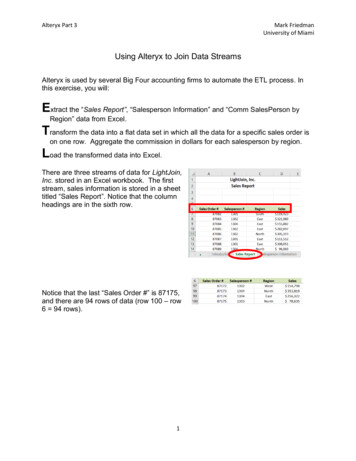
CHAPTER 2. THE VERTICAL SYSTEMThe vertical system of yourscope supplies the display system with the Y axis - or vertical- information for the graph onthe CRT screen. To do this, thevertical system takes the inputsignals and develops deflectionvoltages. The display systemthen uses the deflection voltages to control - deflect-theelectron beam.The vertical system also givesyou a choice of how you connectthe input signals (called coupling and described below).And the vertical system provides internal signals for thetrigger circuit (described inChapter 4). Figure 4 illustratesthe vertical system schematically.Some of the vertical systemcontrols - see the foldout frontpanel illustration for their locations - are: vertical position,sensitivity, and input coupling.“L-Because all 2200s are twochannel scopes, you will haveone set of these switches foreach channel. There are alsotwo switches for choosing thescope’s vertical display modeand one control that allows youto invert the polarity of the channel 2 signal.For the exercises in this chapter, you’ll need a 10X probe likethe Tektronix P6120 10X Probessupplied with every 2200 Seriesscope.Vertical PositionYour scope’s POSITION controlslet you place the trace exactlywhere you want it on the screen.The two vertical POSITION controls (there’s one for each channel) change the vertical placement of the traces from eachvertical channel; the horizontalPOSITION control changes thehorizontal position of bothchannels at once.N’lENJAl Figure 4.THE VERTICAL SYSTEM of a Tektronix 2200 Series scope consists of two identicalchannels though only one is shown in the drawing. Each channel has circuits tocouple an input signal to that channel, attenuate (reduce) the input signal whennecessary, preamplify it, delay it, and finally amplify the signal for use by the displaysystem. The delay line lets you see the beginning of a waveform even when thescope is triggering on it.6Input CouplingThe input coupling switch foreach vertical channel lets youcontrol how the input signal iscoupled to the vertical channel.DC (the abbreviation normallystands for direct current) inputcoupling lets you see all of aninput signal. AC (alternating current) coupling blocks the constant signal components andpermits only the alternatingcomponents of the input signalto reach the channel. An illustration of the differences is shownin Figure 5.The middle position of thecoupling switches is markedGND for ground. Choosing thisposition disconnects the inputsignal from the vertical systemand makes a triggered displayshow the scope’s chassisground. The position of the traceon the screen in this mode is theground reference level. Switching from AC or DC to GND andback is a handy way to measuresignal voltage levels with respect to chassis ground. (Usingthe GND position does notground the signal in the circuityou’re probing.)Vertical SensitivityA volts/division rotary switchcontrols the sensitivity of eachvertical channel. Having different sensitivities extends therange of the scope’s applications; with a VOLTS/DIV switch,a multipurpose scope is capable of accurately displaying signal levels from millivolts to manyvolts.Using the volts/divisionswitch to change sensitivity alsochanges the scale factor, thevalue of each major division onthe screen. Each setting of thecontrol knob is marked with anumber that represents thescale factor for that channel. Forexample, with a setting of 10 V,
PART Ieach of the eight vertical majordivisions represents 10 volts andthe entire screen can show 80volts from bottom to top. With aVOLTSDIV se
2215 Portable Oscilloscopes. The 2213 is a dual-channel, 60 MHz portable designed as an easy-to-use, lightweight, general-purpose oscilloscope. The 2215 is a dual time base oscilloscope with more features and capabilities; it’ s included so you will understand dual time base scopes and ap