Transcription
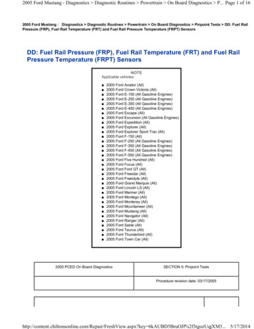
Sniper Stealth 4500 (550-841 Shiny, 550-842 Black, & 550-843 Gold)Holley Sniper EFI FUEL INJECTION INSTALLATION MANUAL1
Read this manual before using this product.WARNING!This instruction manual must be read and fully understood before beginning installation. If the instructionsare not fully understood, installation should not be attempted. Failure to follow the instructions may result insubsequent system failure and could result in serious personal injury and/or property damage. Keep thismanual.For the safety and protection of you and others as well as your vehicle, only a trained mechanic havingadequate fuel system experience should perform the installation, adjustment, and repair.While undertaking any work involving the fuel system, it is particularly important to remember one of the verybasic principles of safety: fuel vapors are heavier than air and tend to collect in low places where an explosivefuel/air mixture may be ignited by any spark or flame resulting in property damage, personal injury, and/ordeath. Extreme caution must be exercised to prevent spillage and thus eliminate the formation of such fuelvapors. All work involving this product and the fuel system generally MUST be performed in a well-ventilatedarea. Do NOT smoke or have an open flame present near gasoline vapors or an explosion may result.Any components damaged due to failure to follow these instructions will not be covered by the warranty.Failure of any one component does not constitute, nor does it justify, warranty of the complete system.Individual service items are available for replacement of components. If assistance is required or if you needfurther warranty clarification, please call Holley Technical Service at 1 (270) 781-9741.2
TABLE OF CONTENTSINTRODUCTION & SYSTEM REQUIREMENTS .5Engine Requirements .5Fuel System Requirements .5TOOLS REQUIRED FOR INSTALLATION .5PARTS IDENTIFICATION .6PREPARING THE THROTTLE BODY FOR INSTALLATION .7THROTTLE BODY INSTALLATION . 7OXYGEN SENSOR INSTALLATION . 8COOLANT TEMPATURE SENSOR INSTALLATION .9FUEL SYSTEM CONNECTIONS . 10ECU WIRING OVERVIEW . 11BASIC WIRING INSTALLATION. 12GENERAL WIRING REFERENCE. 13Throttle Body Connections . 13Pigtail & Loose Wire Connections. 13Connecting Sniper EFI Touchscreen LCD to Sniper EFI . 14NON TIMING CONTROLLED IGNITION SYSTEM WIRING . 17Coil (-) [no timing control] . 17Ignition Box Tach Output (No Timing Control) . 18TIMING CONTROLLED IGNITION SYSYEM WIRING . 20Timing Control Preface: . 20MSD (Magnetic) Distributor [Timing Control] . 20Holley Dual Sync Distributor [Timing Control] . 25Sniper EFI HyperSpark Distributor [Timing Control] . 31HANDHELD NAVIGATION . 32Possible Screens . 32INITIAL EFI SETUP . 34Calibration Wizards. 34Sensor Verification. 38Prestart Checklist. 39First Startup . 39After Startup. 39Ignition Timing Check (without Timing Control) . 40Ignition Timing Check (ECU Controlling Timing). 41THROTTLE BLADE ADJUSTMENT . 42SYSTEM SETUP . 43Ignition System Setup . 43BASIC TUNING. 44Basic Fuel . 44Target AFR . 45Acceleration Enrichment . 45Fuel Prime . 46Closed Loop Enable/Disable . 46Learn Enable/Disable . 473
Basic Idle . 47Spark . 48SYSTEM TUNING. 48Outputs . 49Engine Setup . 50Sniper Setup . 50Ignition Setup . 51Static Timing . 51ADVANCED TUNING . 52IAC Rampdown. 54Idle Spark . 55Idle Speed . 56Advanced 2 . 56SNIPER EFI MONITOR . 57Monitors . 57Multi-Gauge . 58Changing Monitor Channel Scaling . 58Custom Configuring Dash 1 Dash 2 or Dash 3 . 60NITROUS TUNING ON HANDHELD . 60BOOST CONTROL ON HANDHELD . 60ADVANCED TABLES ON HANDHELD . 61TUNING DEFINITIONS . 61DATALOGGING & FILE TRANSFERS . 70Taking a Datalog with the 3.5” TSCLCD . 70Triggering an Automatic Datalog . 70Changing Diagnostics Type of Datalog . 70Downloading Global Configuration from Sniper EFI Throttle Body to SD card: . 71Loading Calibration into Sniper EFI ECU . 71LAPTOP SUPPORT. 72Viewing Global Configuration with Sniper EFI Software without USB Cable: . 72Viewing Datalog with Sniper EFI Software: . 73TROUBLESHOOTING . 74Troubleshooting Guide . 74Sensor Verification. 74Sensor Diagnostics and Statuses . 744
INTRODUCTION & SYSTEM REQUIREMENTSHolley Performance Products has written this manual for the installation of the Sniper EFI TBI fuel injection system.This basic manual contains the information necessary for the installation of the throttle body, wiring, and sensors.Please read all the WARNINGS and NOTES, as they contain valuable information that can save you time and money.It is our intent to provide the best possible products for our customer; products that perform properly and satisfy yourexpectations.Engine RequirementsBefore moving forward with the installation, please verify your vehicle meets the engine and fuel system requirementsbelow: Engine is in sound mechanical conditionEngine horsepower is between 800-1500Engine is an 8 cylinderEngine has a 4 barrel, 4500 style flange intake manifold*Unleaded fuel onlyAny RTV silicone sealants used on the engine are sensor safe* Any 4500 flange intake manifold will work. Make sure to use proper gaskets to seal the throttle body to the intakemanifold and ensure that there are no vacuum leaks.Fuel System RequirementsThe Sniper EFI system requires a high pressure fuel pump capable of operating at 60 psi with at least 50 gallon perhour of fuel flow (more fuel flow may be needed for higher horsepower engines). When selecting a pump, and lines, besure each component is designed to perform at high pressure. Holley offers a variety of fuel pumps, hoses andaccessories to complete your installation. For best results, Holley strongly recommends an in-tank pump. Installing thefuel pump in the tank results in quieter operation, less chance of cavitation and a reduction in pump temperature. Ifmounting the pump in the tank is not an option, install the pump as close as possible to the tank. Within 2-feet ofsending unit is recommended. Once the fuel system is installed checking the fuel pressure on the inlet side of theSniper EFI is recommended, fuel pressure needs to be between 55-65 PSI.TOOLS REQUIRED FOR INSTALLATION Standard Wrench SetMedium Blade ScrewdriverDrill and Assorted Bit SizesFactory Service Manual for your vehicle Small Blade Screwdriver #2 Phillips Screwdriver Terminal Crimping Tool 7/8” Drill Bit (step-bit recommended) Allen Wrench Set Digital VoltmeterAn assistant is necessary for some installation and adjustment procedures and should be present for safety reasons.WARNING! Before disconnecting the battery, we recommend locating a Clean Switched 12 volt ignition source.This source needs to have 12 volts while cranking and with the key in the run position. Disconnect batterybefore proceeding with any work to the vehicle.5
PARTS IDENTIFICATIONITEM #12IMAGEDESCRIPTIONBosch Wide BandOxygen SensorClamp-on OxygenSensor BungQTY11SERVICE P/NNOTES Use of leaded fuel will degrade sensor.Prolongedusewillrequireperiodicreplacement. Mounting procedure below is critical for systemperformance Requires 3/4” hole to be drilled Mounting procedure below is critical for systemperformance In order to help prevent condensation in theexhaust from damaging the sensor, ensurethat the sensor is installed with at least 10degrees of vertical angle.3/8” NPT Threads – Adapters to ½” NPT areavailable554-155534-58 3CoolantTemperatureSensor1Sniper EFIThrottle BodyAssembly15Air CleanerGasket16Open & 4 HoleFlange Gaskets173.5” TouchScreen Controller18Output Harness19Main Harnessand IgnitionAdapter14543-120 Must be installed in a coolant passage in eitherthe intake manifold or cylinder head. Do notinstall in thermostat housing. 4500 Flange Sniper EFI Throttle Body Includes ECU, fuel injectors, Manifold AirPressure (MAP) sensor, Throttle PositionSensor (TPS), Manifold Air Temp Sensor(MAT), and an Idle Air Control Valve (IAC) Gaskets for mounting throttle body to intakemanifold553-115 Includes harness to connect directly to CANconnector558-491 Mates to Input/Output connector on MainWiring Harness and can be used for A/CShutdown, Electric Fan #1 Output, and/orElectric Fan #2 Output.N/A558-4906
PREPARING THE THROTTLE BODY FOR INSTALLATIONIf the Sniper EFI will be used on a N/A engine, no changes need to be made to the throttle body.Draw through Supercharger Applications: When using the Sniper EFI on a draw through boosted application (I.E.positive displacement blower such as an 8/71), the throttle body must be converted to read manifold pressure from aremote source that sees manifold pressure. To do this, remove the 1/16” NPT plug nearest the wires on the front ofthe throttle body. Thread in a 1/16” NPT barbed nipple. Next, install the supplied 10-32 set screw into the machinedport on the bottom of the throttle body. It is also recommended to take a small punch and peen the casting around theset screw in 2-3 places. The installation of this set screw is critical to system operation. Failure to do so will causefalse MAP sensor readings.THROTTLE BODY INSTALLATION1.Start by labeling all vacuum lines for easy identification, i.e. brake booster & vac advance for distributor. If anylines appear damaged, now is the time to replace them. Next, remove the carburetor, clean the gasket matingsurface, and install the provided intake flange gasket on the intake manifold.2.Place the Sniper EFI throttle body on top of the new flange gasket on the manifold. Using the correct length carbstud and nuts, tighten the Sniper EFI throttle body down progressively in a “criss-cross” pattern (60-80 in.lbs.).3.Install the throttle linkage to the Sniper EFI throttle body. Be sure to check for any b
Apr 30, 2018 · 1 Sniper Stealth 4500 (550-841 Shiny, 550-842 Black, & 550-843 G