Transcription
www.ti.comTable of ContentsFunctional Safety InformationTLV3601-Q1, TLV3602-Q1Functional Safety FIT Rate, FMD and Pin FMATable of Contents1 Overview.22 Functional Safety Failure In Time (FIT) Rates. 32.1 DCK, DBV, DGK, DSG Packages. 33 Failure Mode Distribution (FMD). 44 Pin Failure Mode Analysis (Pin FMA).54.1 DCK and DBV Package. 55 Revision History.6TrademarksAll trademarks are the property of their respective owners.SFFS231B – AUGUST 2021 – REVISED JULY 2022Submit Document FeedbackTLV3601-Q1, TLV3602-Q1Functional Safety FIT Rate, FMD and Pin FMACopyright 2022 Texas Instruments Incorporated1
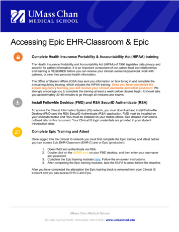
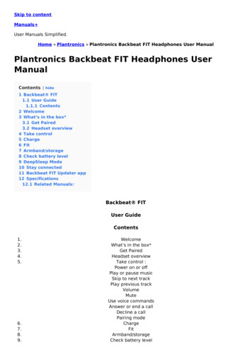
Overviewwww.ti.com1 OverviewThis document contains information for TLV3601-Q1 (DCK and DBV packages) and TLV3602-Q1 (DGK andDSG packages) to aid in a functional safety system design. Information provided are: Functional Safety Failure In Time (FIT) rates of the semiconductor component estimated by the application ofindustry reliability standardsComponent failure modes and their distribution (FMD) based on the primary function of the devicePin failure mode analysis (Pin FMA)Figure 1-1 shows the device functional block diagram of single channel for reference.Figure 1-1. Functional Block Diagram per ChannelTLV3601-Q1 and TLV3602-Q1 were developed using a quality-managed development process, but was notdeveloped in accordance with the IEC 61508 or ISO 26262 standards.ADVANCE INFORMATION for preproduction products; subject to change without notice.2TLV3601-Q1, TLV3602-Q1Functional Safety FIT Rate, FMD and Pin FMASFFS231B – AUGUST 2021 – REVISED JULY 2022Submit Document FeedbackCopyright 2022 Texas Instruments Incorporated
www.ti.comFunctional Safety Failure In Time (FIT) Rates2 Functional Safety Failure In Time (FIT) Rates2.1 DCK, DBV, DGK, DSG PackagesThis section provides Functional Safety Failure In Time (FIT) rates for the DCK and DBV packages of TLV3601Q1 and DGK and DSG packages of TLV3602-Q1 based on two different industry-wide used reliability standards: Table 2-1 provides FIT rates based on IEC TR 62380 / ISO 26262 part 11Table 2-3 provides FIT rates based on the Siemens Norm SN 29500-2Table 2-1. TLV3601-Q1 Component Failure Rates per IEC TR 62380 / ISO 26262 Part 11FIT IEC TR 62380 / ISO 26262DCK FIT (Failures Per 109 Hours)DBV FIT (Failures Per 109 Hours)Total Component FIT Rate34Die FIT Rate22Package FIT Rate12Table 2-2. TLV3602-Q1 Component Failure Rates per IEC TR 62380 / ISO 26262 Part 11FIT IEC TR 62380 / ISO 26262DGK FIT (Failures Per 109 Hours)DBV FIT (Failures Per 109 Hours)Total Component FIT Rate74Die FIT Rate32Package FIT Rate42The failure rate and mission profile information in Table 2-1 comes from the Reliability data handbook IEC TR62380 / ISO 26262 part 11: Mission Profile: Motor Control from Table 11TLV3601-Q1 Power dissipation: 19.8 mWTLV3602-Q1 Power dissipation: 39.6 mWClimate type: World-wide Table 8Package factor (lambda 3): Table 17bSubstrate Material: FR4EOS FIT rate assumed: 0 FITTable 2-3. TLV3601-Q1, TLV3602-Q1 Component Failure Rates per Siemens Norm SN 29500-2TableCategoryReference FIT RateReference Virtual TJ4CMOS, BICMOSDigital, analog / mixed12 FIT55 CThe Reference FIT Rate and Reference Virtual TJ (junction temperature) in Table 2-3 come from the SiemensNorm SN 29500-2 tables 1 through 5. Failure rates under operating conditions are calculated from the referencefailure rate and virtual junction temperature using conversion information in SN 29500-2 section 4.SFFS231B – AUGUST 2021 – REVISED JULY 2022Submit Document FeedbackTLV3601-Q1, TLV3602-Q1Functional Safety FIT Rate, FMD and Pin FMACopyright 2022 Texas Instruments Incorporated3
Failure Mode Distribution (FMD)www.ti.com3 Failure Mode Distribution (FMD)The failure mode distribution estimation for TLV3601-Q1 and TLV3602-Q1 in Table 3-1 comes from thecombination of common failure modes listed in standards such as IEC 61508 and ISO 26262, the ratio ofsub-circuit function size and complexity and from best engineering judgment.The failure modes listed in this section reflect random failure events and do not include failures due to misuse oroverstress.Table 3-1. Die Failure Modes and DistributionDie Failure ModesFailure Mode Distribution (%)OUTOpen (HIZ)15%OUTSaturate high25%OUTSaturate low25%OUTFunctional not in specification30%ShortCircuit any two pins5%The FMD in Table 3-1 excludes short circuit faults across the isolation barrier. Faults for short circuit across theisolation barrier can be excluded according to ISO 61800-5-2:2016 if the following requirements are fulfilled:1. The signal isolation component is OVC III according to IEC 61800-5-1. If a SELV/PELV power supply isused, pollution degree 2/OVC II applies. All requirements of IEC 61800-5-1:2007, 4.3.6 apply.2. Measures are taken to ensure that an internal failure of the signal isolation component cannot result inexcessive temperature of its insulating material.Creepage and clearance requirements should be applied according to the specific equipment isolation standardsof an application. Care should be taken to maintain the creepage and clearance distance of a board design toensure that the mounting pads of the isolator on the printed-circuit board do not reduce this distance.4TLV3601-Q1, TLV3602-Q1Functional Safety FIT Rate, FMD and Pin FMASFFS231B – AUGUST 2021 – REVISED JULY 2022Submit Document FeedbackCopyright 2022 Texas Instruments Incorporated
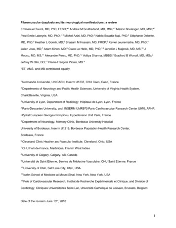
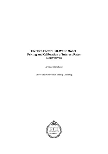
www.ti.comPin Failure Mode Analysis (Pin FMA)4 Pin Failure Mode Analysis (Pin FMA)This section provides a Failure Mode Analysis (FMA) for the pins of the TLV3601-Q1 (DCK package). The failuremodes covered in this document include the typical pin-by-pin failure scenarios (results are similarly applicablefor TLV3602-Q1): Pin short-circuited to Ground (see Table 4-2.)Pin open-circuited (seeTable 4-3.)Pin short-circuited to an adjacent pin (see Table 4-4.)Pin short-circuited to supply (see Table 4-5.)Table 4-2 through Table 4-5 also indicate how these pin conditions can affect the device as per the failure effectsclassification in Table 4-1.Table 4-1. TI Classification of Failure EffectsClassFailure EffectsAPotential device damage that affects functionalityBNo device damage, but loss of functionalityCNo device damage, but performance degradationDNo device damage, no impact to functionality or performanceFollowing are the assumptions of use and the device configuration assumed for the pin FMA in this section: Each pin is assessed individuallyAll other pins are configured correctly for device functionality4.1 DCK and DBV PackageFigure 4-1 shows the TLV3601-Q1 pin diagram for the DCK and DBV packages. For a detailed description of thedevice pins please refer to the Pin Configuration and Functions section in the TLV3601-Q1 data sheet.Figure 4-1. Pin Diagram (DCK and DBV) PackageSFFS231B – AUGUST 2021 – REVISED JULY 2022Submit Document FeedbackTLV3601-Q1, TLV3602-Q1Functional Safety FIT Rate, FMD and Pin FMACopyright 2022 Texas Instruments Incorporated5
Revision Historywww.ti.comTable 4-2. Pin FMA for Device Pins Short-Circuited to GroundDescription of Potential Failure Effect(s)FailureEffectClassPin NamePin No.OUT1Thermal stress due to high power dissipationAVEE2No change if same node as GNDDIN 3Output goes low, if other input is positiveBIN-4Output goes high, if other input is positiveBVCC5Main suppy shorted out (no power to device)BTable 4-3. Pin FMA for Device Pins Open-CircuitedDescription of Potential Failure Effect(s)FailureEffectClassPin NamePin No.OUT1Output can't drive application loadBVEE2Lowest voltage pin will drive GND pin internally (via diode)AIN 3Output may be low or highBIN-4Output may be low or highBVCC5Main suppy open (no power to device)BTable 4-4. Pin FMA for Device Pins Short-Circuited to Adjacent PinDescription of Potential Failure Effect(s)FailureEffectClassPin NamePin No.Shorted toOUT1VEEThermal stress due to high power dissipationAVEE2IN Output goes low, if other input is positiveBIN 3IN-Output may be low or highBIN-4VCCOutput goes low, if other input is less positiveBVCC5OUTThermal stress due to high power dissipationATable 4-5. Pin FMA for Device Pins Short-Circuited to SupplyDescription of Potential Failure Effect(s)FailureEffectClassPin NamePin No.OUT1Thermal stress due to high power dissipationAVEE2Main suppy shorted out (no power to device)BIN 3Output goes high, if other input is less positiveBIN-4Output goes low, if other input is less positiveBVCC5No change if same node as VCCD5 Revision HistoryNOTE: Page numbers for previous revisions may differ from page numbers in the current version.Changes from Revision A (August 2021) to Revision B (June 2022)Page Added TLV3602-Q1 to document. 26TLV3601-Q1, TLV3602-Q1Functional Safety FIT Rate, FMD and Pin FMASFFS231B – AUGUST 2021 – REVISED JULY 2022Submit Document FeedbackCopyright 2022 Texas Instruments Incorporated
IMPORTANT NOTICE AND DISCLAIMERTI PROVIDES TECHNICAL AND RELIABILITY DATA (INCLUDING DATA SHEETS), DESIGN RESOURCES (INCLUDING REFERENCEDESIGNS), APPLICATION OR OTHER DESIGN ADVICE, WEB TOOLS, SAFETY INFORMATION, AND OTHER RESOURCES “AS IS”AND WITH ALL FAULTS, AND DISCLAIMS ALL WARRANTIES, EXPRESS AND IMPLIED, INCLUDING WITHOUT LIMITATION ANYIMPLIED WARRANTIES OF MERCHANTABILITY, FITNESS FOR A PARTICULAR PURPOSE OR NON-INFRINGEMENT OF THIRDPARTY INTELLECTUAL PROPERTY RIGHTS.These resources are intended for skilled developers designing with TI products. You are solely responsible for (1) selecting the appropriateTI products for your application, (2) designing, validating and testing your application, and (3) ensuring your application meets applicablestandards, and any other safety, security, regulatory or other requirements.These resources are subject to change without notice. TI grants you permission to use these resources only for development of anapplication that uses the TI products described in the resource. Other reproduction and display of these resources is prohibited. No licenseis granted to any other TI intellectual property right or to any third party intellectual property right. TI disclaims responsibility for, and youwill fully indemnify TI and its representatives against, any claims, damages, costs, losses, and liabilities arising out of your use of theseresources.TI’s products are provided subject to TI’s Terms of Sale or other applicable terms available either on ti.com or provided in conjunction withsuch TI products. TI’s provision of these resources does not expand or otherwise alter TI’s applicable warranties or warranty disclaimers forTI products.TI objects to and rejects any additional or different terms you may have proposed. IMPORTANT NOTICEMailing Address: Texas Instruments, Post Office Box 655303, Dallas, Texas 75265Copyright 2022, Texas Instruments Incorporated
This document contains information for TLV3601-Q1 (DCK and DBV packages) and TLV3602-Q1 (DGK and DSG packages) to aid in a functional safety system design. Information provided are: Functional Safety Failure In Time (FIT) rates of the semiconductor component estimated by the application of industry reliability standards