Transcription
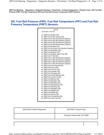
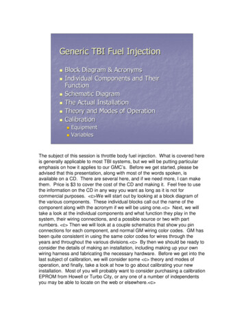
Generic TBI Fuel Injection Block Diagram & AcronymsIndividual Components and TheirFunctionSchematic DiagramThe Actual InstallationTheory and Modes of OperationCalibration EquipmentVariablesThe subject of this session is throttle body fuel injection. What is covered hereis generally applicable to most TBI systems, but we will be putting particularemphasis on how it applies to our GMC’s. Before we get started, please beadvised that this presentation, along with most of the words spoken, isavailable on a CD. There are several here, and if we need more, I can makethem. Price is 3 to cover the cost of the CD and making it. Feel free to usethe information on the CD in any way you want as long as it is not forcommercial purposes. c We will start out by looking at a block diagram ofthe various components. These individual blocks call out the name of thecomponent along with the acronym if we will be using one. c Next, we willtake a look at the individual components and what function they play in thesystem, their wiring connections, and a possible source or two with partnumbers. c Then we will look at a couple schematics that show you pinconnections for each component, and normal GM wiring color codes. GM hasbeen quite consistent in using the same color codes for wires through theyears and throughout the various divisions. c By then we should be ready toconsider the details of making an installation, including making up your ownwiring harness and fabricating the necessary hardware. Before we get into thelast subject of calibration, we will consider some c theory and modes ofoperation, and finally, take a look at how to go about calibrating your newinstallation. Most of you will probably want to consider purchasing a calibrationEPROM from Howell or Turbo City, or any one of a number of independentsyou may be able to locate on the web or elsewhere. c
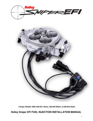
ECT(Engine CoolantTemperature)O2(Exhaust GasOxygenSensor)SESALDL(Service EngineSoon ePressure Sensor)(Idle AirControl)ECMTPSFuel PumpRelay(EngineControlModule)(Throttle PositionSensor)FuelInjectorVss(Vehicle SpeedSensor)ESCKnock Sensor(ElectronicSpark DistributorCoilFirst, the “big picture” block diagram. The components you will see on the leftare sensors, or inputs into the ECM. The components on the right arecontrolled by the ECM based on the inputs it receives from the sensors. Theinputs are: c O2 Exhaust Gas Oxygen Content Sensor, c ECT EngineCoolant Temperature Sensor, c MAP Manifold Absolute Pressure Sensor, c TPS Throttle Position Sensor, c Vss Vehicle Speed Sensor (not alwaysused), c and the Knock Sensor c whose signal is conditioned by the ESCElectronic Spark Control Module before reaching the ECM. The generationECM after the one we normally use in our GMC’s is usually referred to as aPCM (Powertrain Control Module). It contains the knock sensor signalconditioning on board, so the ESC was pretty much eliminated in the mid 90’swith the PCM’s. c Finally, we have the Crank Signal whose job it is to tellthe ECM we are trying to start the engine. On the other side of the equation,we have c SES Service Engine Soon Light, c ALDL DiagnosticsConnector, both of which control nothing, but provide information and meansof human interface to the ECM. The components actually controlled by theECM are: c IAC Idle Air Control, c Fuel Pump Relay, c the two fuelinjectors, c and the spark timing. The computer tells the Control Module inthe Distributor how much to advance/retard spark, but the Control Moduleactually tells the Coil when to fire based on information from the ECM and themagnetic pickup in the Distributor (that’s where initial timing enters in). TheDistributor rotor and cap send the spark to the correct cylinder. c
Generic TBI Fuel Injection Block Diagram & AcronymsIndividual Components and TheirFunctionWe have covered c the block diagram and acronyms and are now ready totake a look at the c function of the individual components, and some generalinformation about them, and how to procure them. c
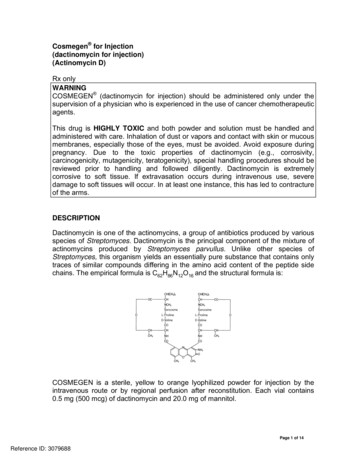
O2 Sensor Screws into exhaust manifold orexhaust pipeConnects directly to ECMSenses oxygen level in exhaustgases and feeds info tocomputer which adjusts fueldelivery to match 14.7 air/fuelratioGM P/N 25166816 (Delphi #ES10004)ES10004) used widely on GMenginesLet’s talk first about the c O2 Sensor. c It screws directly into the exhaustmanifold or the exhaust pipe as close to the manifold as possible. If you screwit into the exhaust pipe, you will first have to weld a suitable bung onto thepipe. The bung can be procured from Summit or any number of otherplaces. c The sensor’s job is to send a voltage to the ECM which tells it toadjust fuel delivery to match the target 14.7 air/fuel ratio. c These are widelyavailable in wrecking yards off almost any GM vehicle newer than the late80’s, but I suggest you buy a new one. The single wire sensor works great forour application if placed reasonably close to the manifold. It needs highexhaust gas temperature to function properly. By the way, the yellowunderlined text used throughout this presentation can be clicked upon to directyou to further information on the internet if you get a PowerPoint copy of thissession. c
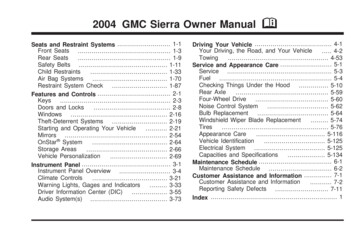
O2 Sensor Types We typically use a single wire sensor (groundsthrough block).Exhaust gases heat to operating temp.In or very near exhaust manifold for quickestheatHas a very narrow operating band (essentiallyover/under 14.7 AFR)Three wire sensors (12V, GND, and signal leads)work much like single wire except they self heat.Four wire sensors have two signal leads; oneindicates high AFR, the other low AFR.A wide band O2 sensor has a much wider band. Very helpful in calibration workGood for a couple points AFR either side of 14.7As I mentioned, we typically use c the single wire sensor which c takesadvantage of exhaust gas heat to reach operating temperature. c That iswhy it needs to be within a foot or so of the exhaust manifold, preferably closerto reach temperature faster. c It has a very narrow operating band, and isessentially like an on/off switch. It either reads over or under 14.7 AFR. c The three wire sensor is much like the single wire sensor, except it has twoadditional wires to a heater element that provides quick heat to get it up tooperating temperature quickly. c The four wire sensor has two signals; onefor high AFR and one for low AFR. At least it provides for a narrow band thatsays AFR is OK rather than always being over or under the target 14.7 AFR. c Some vehicles use a wide band sensor which can give fairly accuratereadings a couple points on either side of 14.7. These are most helpful if youplan to do your own calibration work, or if you would like to be assured of arich enough mixture at or near WOT. c
Why 14.7 air/fuel ratio ? 14.7 AFR is NOT necessarilymost fuel efficient, but the CC(catalytic converter) isAs AFR gets leaner, CC becomesmore efficient burning HC & COAs AFR gets richer, CC becomesmore efficient burning NOx14.7 AFR is where they crossand both are 90% eliminatedThe ECM has an unincorporatedhighway mode that leans themixture during cruisingWhy is the target AFR 14.7:1? It is a common misconception that the mostefficient fuel economy is obtained at 14.7. This is not necessarily true.However, it is the most efficient operating point for the catalytic converter. c If you take a look at the 3 Way Converter Function Graph which plotsconverter efficiency vs. AFR, you will note that c as the AFR gets leaner,the CC becomes more efficient in controlling hydrocarbons and carbonmonoxide. c As AFR gets richer, the CC becomes more efficient incontrolling oxides of nitrogen. c Where they cross, the AFR is 14.7:1, and atthat point, all the nasties are 90% eliminated. Thus, the target of 14.7 AFR isdefined by catalytic converter considerations, not maximum fuel economy. c The ECM does have an unincorporated feature called Highway Mode. Whenin highway mode, O2 feedback is not used to control fuel delivery, but is ratheran open loop enleanment process to maximize fuel economy. I readsomewhere that the reason it is not incorporated is because someonedetermined the feature to be a nifty way of defeating emissions controls toimprove economy. DUH! c Russ Harms is experimenting with the HighwayMode in his PFI coach.
ECT Sensor Connects directly to ECMwith two wire connectorGM P/N 12146312 or 29036979 (DelphiTS10075)TS10075) used widely in GM vehiclesSensor is a non linear thermistor which variesresistance with temperature. The ECM sends aprecise 5V reference to the thermistor,thermistor, and usesthe return voltage to establish temperature bymeans of a look up table of voltage vs.temperature.Moving on to something much more straight forward and less controversial,let’s consider the ECT sensor. c It connects directly to the ECM by meansof two connection wires. c These things are a dime a dozen in wreckingyards and they almost never fail, so save yourself 20- 30 and pick one up atyou favorite men’s mall. c The sensor element is a non linear thermistorwhich varies resistance with temperature. The ECM sends a precise 5Vreference to the thermistor. It reads the return voltage and compares it to alookup table embedded in the program ROM to establish actual temperature.
What does ECT affect? Fuel deliveryIgnition timing relative to initial settingKnock detection system, thus sparkretardIdle speedTorque converter clutch application(switch pitch converter?)What does the ECT sensor affect? c Fuel delivery, c Ignition timingrelative to initial setting, c knock detection system, thus spark retard, c idle speed, c and torque converter clutch application in later vehicles. Wehave a switch pitch torque converter in our GMC and I would like toexperiment with using the ECM to control it. c
MAP Sensor Three wire connection to ECMplus manifold vacuumGM P/N 2131545, 16137039,16017460 (Delphi # PS10076)PS10076)widely used throughout GMprior to 1995Do NOT get one off a super or turbo chargedengine, or from pre TBI cars such as the 307 Oldsengine. They are MDP (manifold differentialpressure) sensorsOutput is opposite manifold vacuum; 100 kPa(kilopascal) 0”0” vacuum 1 atmosphere pressureThe MAP Sensor has a three wire connection to the ECM consisting of a 5Vreference, ground, and a signal wire. It is a variable resistor that variesresistance in proportion to absolute pressure and sends nominally a 0 to 5Vsignal to the ECM. The other connection to the MAP Sensor is to manifoldvacuum. c These are plentiful in salvage yards because they were widelyused throughout GM up until about 1995. c Do not get one off a super orturbo charged engine, or from pre TBI cars such as the 307 Olds engine youwill be looking for to find a suitable distributor. They are manifold differentialpressure sensors as opposed to absolute pressure sensors. c Output is a bitconfusing because it is opposite what we are used to dealing with, and istypically shown in kPa (kilopascals). 100 kPa is nominally equal to 0” ofvacuum at sea level which also equals 1 atmosphere of pressure.Temperature and humidity and other atmospheric conditions affectatmospheric pressure a little bit, and altitude affects it a lot, so on top of Pike’sPeak, 100 kPa is considerably more than atmospheric pressure. Thus in thesignal sent to the ECM by the MAP sensor is automatically altitudecompensated. c
What does MAP affect? Key in calculating air flow in the SD(speed density) system we use asopposed to MAF (mass air flow) used inmost PFI engines Air flow (along with other things) determinesfuel delivery rate.Spark calculationsBarometric pressure readingsSwitch pitch on/off if usedMAP is one of two key factors in calculating air flow in the SD (speed density)system we use as opposed to MAF (mass air flow) systems used on most PFImodern day engines. c Air flow is obviously the most important factor indetermining fuel delivery rate, although there are a number of other factors theECM takes into account when calculating injector pulse width. c MAP is alsoused in making spark advance/retard calculations, c Barometric pressurereadings, c and in turning our imaginary switch pitch on and off. c
TPS Three wire connector toECM5V reference is sent tothe TPS by the ECM, .5Vis returned @ closedthrottle, 4.5V @ openSS10424SS10425Earlier 454’s used the style to the left; laterones used the style to the right. Changedaround 1990.Both were widely used throughout GMThe TPS (throttle position sensor) also has a three wire connector to the ECMconsisting of a 5V reference, ground, and the signal wire. It is a variableresistor connected to the throttle blade shaft. c At closed throttle, it sendsnominally a .5V signal to the ECM, and at WOT it sends nominally a 4.5Vsignal. It is easy to troubleshoot because you can see the voltage orresistance vary uniformly as you open and close the throttle blade. When Ifirst cranked up my system, it ran, but very erratically and I got TPS errorreadings. The readings coming from the TPS seemed perfect until I finallynoticed the voltage readings were backwards. After swapping the ground and5V wires it ran perfectly. Check the obvious first! It would have saved me afrustrating day had I done that! c Earlier 454’s used the style to the left, andafter about 1990, they used the one to the right. c Both are fairly plentiful insalvage yards as they were used widely throughout GM. c
What does the TPS affect? Like MAP, TP is key in calculating air flow,and thus fuel delivery in our speed densitysystem.Ignition timingSwitch pitch on/off if usedFlooding control – enleans drastically ifWOT while crankingTP is the other key factor, along with MAP mentioned earlier, that is key incalculating air flow and thus fuel delivery in
c We will start out by looking at a block diagram of the various components. These individual blocks call out the name of the component along with the acronym if we will be using one. c Next, we will take a look at the individual components and what function they play in the system, their wiring connections, and a possible source or two with part numbers. c Then we will look at a couple .