Transcription
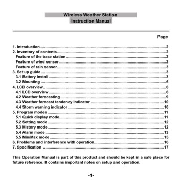
Note: These kits are notlegal for use on pollution controlled vehiclesInstruction Manualfor the following Go EFI System30020 - Go EFI CLASSICWARNING: Cancer and Reproductive Harm - www.P65Warnings.ca.gov.Please read the full instructions before beginning your installation. system. For technical assistance with your Go EFI Classic System,These instructions cover the basic kit installation and setup. Failure call the FiTech EFI Tech Line at (951)340-2624to follow these instructions may result in malfunctioning of theWarning: Caution must be observed when installing any productinvolving fuel system parts. Work in a well ventilated area with anapproved fire extinguisher readily available. Eye protection andother safety apparel should be worn to protect against debris andsprayed gasoline. We recommend having this installation per-formed by an experienced, qualified, automotive technician. Thefinished installation must be thoroughly checked for any fuel system leaks. All safety precautions must be observed when workingwith fuel. Disconnect the battery ground wire (-) before startingthe installation.AFigure 1Go EFI Classic 30020KIT CONTENTS(1) 4-injector throttle body with ClassicCarburetor Gold finish.(4) inlet/outlet port plugs (Installed on throttlebody)(1) Harness “A” (plug-in pigtail use harness)(1) Cable for handheld controller(1) ECU(1) Coolant Temperature Sensor(1) 1/2" NPT to 3/8" NPT Reducer(4) Injectors pre-installed(1) Idle Air Control (Pre-Installed)(1) Throttle Position Sensor (Pre-Installed)(1) MAP Sensor (Pre-Installed)(1) Wide Band O2 Sensor(1) Clamp on O2 Bung Kit(1) Handheld Controller with billet case(1) Windsheild Mount for Controller(1) -06 AN crossover hose with -6AN maleinlet fitting (Pre-Installed)(1) Gasket kitTable of ContentsKit contentsAbout your Go EFI Classic SystemSpecial instructionsEngine protection featureVacuum PortsThrottle Body InstallationWide Band O2 Sensor InstallationAir LeaksInstalling the Harness12222, 33344MAPIACTPSCoolant Sensor InstallationInjectorsWiring the EFI SystemOn-Engine AdjustmentsIAC setupWire Chart14444, 55555, 66Handheld ControllerInitial ProgrammingFan SetupFuel Delivery RequirementsWiring DiagramsWith Ready-to-Run distributorWith HEI distributorWith External CDI Box66678910
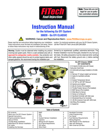
About your FiTech Go EFI SystemCONGRATULATIONS on your purchase of the FiTech EFI System! TheGo EFI Classic System will bolt directly to any 4-BBL Intake Manifold.To fit on a spread bore 4-BBL manifold requires an inexpensiveadapter plate to avoid leaks. Suitable adapter plates are availablefrom several suppliers such as Summit Racing. Your existing distributorand, if so equipped, ignition box functions as before and controls timing.The Go EFI Classic System is self-tuning once the initial setup isperformed using the hand-held controller. When the necessary initialinputs are made with the hand-held controller the Go EFI ClassicSystem creates a base fuel map to get the engine running.Then the self-tuning programming will fine tune the map to produceoptimum power and performance. Through the use of a Wide Band O2Sensor the system can continuously make adjustments in the fueldelivery to provide the correct air/fuel ratio under all climate andaltitude conditions. Several sensors are also integrated in the throttlebody assembly including the Throttle Position Sensor (TPS), and theManifold Absolute Pressure Sensor (MAP). The Wide Band O2 Sensor isinstalled into the exhaust pipe. This system is de-signed with safety inmind and has a self adjusting “limp home” mode. It also has a datalogging feature to track what is going on with the system while it isrunning, to ensure optimal performance.The Go EFI Classic Systems are intended for use with unleadedpump gas. The system is compatible with E-85, but this requiresadvanced tuning knowledge. Maximum horsepower fueling capacity isreduced by approximately 30% with E-85. Fuel system componentsshould be E-85 compatible and in new condition to prevent sludge frombreaking loose. The Go EFI Classic System is designed to be used with streetbased ignition systems: Summit Racing Multi-Spark Digital CDIgnition, MSD Digital 6AL, MSD Street Fire, etc. It will not operate withrace oriented systems such as MSD digital 7AL, 7AL-2, 7AL-3 and 8plus. This system is NOT smog legal. The Go EFI Classic System comes with pre-installed 66-lb flowinjectors and is capable of handling up to 500 hp. Please refer to ignition system’s instructions as some features mayneed to be altered for proper operations of the EFI System. The GoEFI Classic System does not control timing, but depends on the ignitiontiming curve to be correct for optimal throttle response.Always turn off ignition and allow at least 15 seconds Very important note: Your fuel tank must have a ventfor ECU to save if disconnecting batteryto prevent pressure building up inside the tank.Special instructionsMake sure that you remove ALL low pressure hoses, fittings and clampson factory fuel lines and replace them with EFI rated fuel hose. Also theuse of proper flared connections and clamps is a necessity. Be carefulnot to mix 45 and 37 AN fittings, they look similar but will not worktogether. 45 fittings usually come from a hardware store or autoparts store while 37 AN fittings are the ones supplied by FiTech andmost speed shops. Cranking fuel and hard throttle hits (accelerator pump) are tunedby the user. Selecting the right "cam" and engine CID (Cubic InchDisplacement) during setup will get the learning closer. Cruise andwide open throttle (WOT), mixture (trims) are continuously learnedand tweaked by the system. The Go EFI Classic System needs an external fuel pressureregulator set at 58 PSI. A ag-Surge containing a high pressure pumpand regulator is available (PN 40009). This serves as a fuel pressureamplifier and is fed by a low pressure mechanical/elctric pump.Engine Protection FeatureThe Go EFI Classic System is programmed with a limp home mode.This feature does not shut down your system, instead the ECU isdesigned to compensate if a sensor fails. This means, that if for anyreason a sensor fails, that sensor will receive either a default value or asimulated value. This is to ensure that the engine remains running in asafe and controlled manner so that you can get to a repair facility, or toyour home, to resolve the issue. Due to the compensation features ofthe ECU, the way to check if something is going wrong with yoursystem, is by the faultcodes option on the main menu of your hand-held controller. The faultcode comes up under OBD-II, diagnostic standard, but to the right of thecode it will state which sensor is having the problem. A new featureprogrammed into the hand-held is a rev offset. This feature will protectthe engine from long term abuse because it lowers your built in rev limiterenable to prevent over revving and possible engine damage during warmup. It will automatically turn the feature off once your engine reachesoperating temperature.Determining Use of Vacuum PortsDetermine the engine's need for vacuum ports includingported and manifold vacuum. These ports cover accessoriessuch as power brakes, vacuum advance, transmissionmodulator, PCV and possibly more. There are two 3/16" malenipples and three 3/8" male nipples. See figure 1 and 2 forlocation and use of various vacuum nipples.Very Important Note:Your fuel tank MUST be vented toprevent pressure from building upinside the tank.Extra 3/8" nipple for othervacuum accessory or cap ifnot needed.This 3/16" nipplewill provide timed(ported) vacuumThis 3/16" nipplewill provide fullmanifold vacuumFigure 22A
Figure 3Installing the Wide Band Oxygen (O2) SensorUse this 3/8" nipplefor PCV connection.Use this 3/8" nipplefor-power brakebooster.Installing the Throttle BodyFigure 4This is the key component of any EFI system. Only one sensor isrequired. This sensor continuously monitors the exhaust gas mixture andsends the information to the ECU where adjustments are constantly madeto maintain the air/fuel targets.1. The supplied O2 Sensor Bung can be installed in either exhaust bank.2. The Sensor connects to one of the cables in the main wiring harness.See Figure 7 on next page.3. The ideal location for the sensor is in the exhaust collector or within 8inches of the collector itself. It must always be at least 18-inches from theexhaust tip, to prevent reversion and false lean conditions.4. The sensor should be between 10 to 14 above horizontal (see figure6 below) to allow condensation to run off. If this is not adhered to, thesensor is susceptible to damage.5. Never position the sensor on the outside of a bend in the exhausttubing.6. The sensor must always be mounted ahead of any catalytic converter ifvehicle is so equipped.7. Drill a 7/8" diameter hole in the desired location.Figure 61. Place the supplied gasket on the manifold (see above) and place thethrottle body onto the gasket over the existing studs. The throttle bodylinkage must be on the driver’s side of the engine.2. Install the original nuts and washers onto the four carburetor studs.See Figure 4.3. Tighten to 10 lb. ft. of torque in several steps using a crisscrosspattern.8. The supplied bung kit can either be welded in place or clamped onto thepipe. The clamp-on style works well and will not leak. If welded, makesure the bung is welded completely all the way around and does not leak.Thread an M18-1.5 bolt into the bung to prevent distortion.9. Install the sensor into the bung. Tighten securely.10. Connect the O2 sensor to the sub-harness that connects to thethrottle body. See Figure 7.11. Note: The O2 Sensor will not work on "Zoomie" style headers.Figure 5WARNING: Do not start the engine without the sensor cable connected to the throttle body and the EFI system is fully operationalor damage will occur to the sensor!3
AIR LEAKS: It is important that no air leaks exist anywhere in theexhaust system, before or after the sensor, as this will cause falsereadings. This will lead to poor engine performance, including misfires,and the inability to properly auto-tune the EFI. Continued running of thesystem with an exhaust leak can create detonation and possible severeengine damage. Incorrect installation of the sensor, exhaust leaks,and any resulting damage is not covered by the FiTechmanufacturer's warranty. It is very important to ensure your exhaustis leak-free. For optimum EFI operation and function, your exhaust (onthe sensor side) must be totally secure with no leaks.Installing the Wiring HarnessFigure 7GroundTachFuel Pump RelayCTSHandheldControllerO2 SensorFanTo PositiveTerminalof BatteryKey HotFuelPumpTPSInjectorconnectorMAPECUIACWhen installing the harness, the external ECU can be mounted anywhere in the engine bay or through the firewall. Be sure to keep itaway from excessive heat. The harness is made up of the followingconnections: MAP, IAC, O2, TPS, CTS, fan, tach, injectors, ground,positive connection to the battery, ECU, hand-held controller connection, fuel pump, and key hot.MAP ( Manifold Absolute Pressure)Below - Starting with the MAP sensor, the MAP is attached to theoutside of the throttle body on the passenger side. It regulates theinlet air temperature and the manifold absolute pressure. The twosensors (inlet air temp and manifold absolute pressure) are combinedfor ease of installation. The Temperature Manifold Absolute Pressuremeasures the load on the engine and will range between 10 and90kPa while the engine is running. When the engine is off it will read at99-100kPa. See Figure 8 below.IAC (Idle Air Control)The Idle Air ControlSensor gets installeddirectly into the throttlebody. It is used to control the RPM of themotor at idle. See Figure 9, above right.TPS (Throttle Position Sensor)The Throttle PositionFigure 8Sensor’s purpose is torecord how far thethrottle blades are open.Figure 9The ECU maintains thecalibration of the sensorbut, if the TPS reading isnot at 0 at idle then thesensor needs to berecalibrated. See Figure10.CTS (Coolant Temp Sensor)The Coolant Temperature Sensor cable plugs into a supplied sensor fitted into the manifold.It is used to measure the temperature of the engine coolant. Thesensor then sends the information to the ECU to adjust fuel.See Figures 11 and 12 on the next page.Figure 104
Figure 12Figure 11Above - The supplied Coolant Temperature Sensor is threaded intothe water port in the intake manifold. Use Teflon tape on threads.InjectorsAbove - The CTS connector on the main wiring harness is pluggedinto the Coolant Temperature Sensor in the manifold. (1/2" NPT adaptersupplied in kit)Figure 13Figure 14Injector sub harnessconnectorInjector sub-harnessAbove - The throttle body has four 80-lb injectors already See Figure 7. Connect the injector sub-harness onto the maininstalled. This arrangement will allow the system to supply enough harness. Make sure the connectors are securely fastened.fuel flow for up to 650 HP. The throttle body has the injector subOn Engine-Adjustmentsharness pre-installed and ready to go.When you set idle speed, you will notice some new sounds. The first isticking from the injectors and it is normal. You may also hear airWiring the EFI SystemSee the wire chart (Figure 16 on page 6) which lists each wire whooshing or whistling at idle. Barring a vacuum leak, this is likely thebypassed air from the Idle Air Control (IAC valve) and this is normal. Thein Harness "A" that is used in the system and what it connects to.IAC valve maintains idle speed when the AC compressor or electric fansNOTE: Typically some of the wires listed in the chart on the nextclick on.page may need to be extended. It is strongly suggested that anyIAC Setupwire ex-tensions are made with the same gauge and color wire as isused in the supplied harness. Make connections as a soldered The idle screw on the throttle body needs to be adjusted. This needs to beset so that the IAC value is nearly closed when fully warmed up and injoint rather than a crimped connection. Utilize a shrink wrappedidle 3-10 IAC Steps are recommended for a fully warm engine, out of gear,sleeve covering all connections.at idle. When the engine is at idle, the IAC will learn the necessary positionAllmodifications Figure 15tomaintain the RPM at the Target Idle Speed. When loads are placed onmade to wiring canFusetheengine or when the throttle is open, the IAC steps will move around,only be made onBatterythisis normal. It’s best to adjust this screw from a more open position towires listed in WireGroundstartwith. This will allow the engine to start at a high idle, which willChart Figure 16 on30makeadjusting the IAC easier. Follow this procedure:8685Relaythe next page such87Ign/Accas extensions orCircuit Fuse1. Start the engine and in your Handheld go under "initial set-up."cuts. Any modifica- Ground2. Go to “idle setup” and find “idle set mode” and switch to "Adjust"tion of the ECU mainFan 1 - Gray Wire3. Start the vehicle and find IAC Steps on the dashboard. This numberharness (see FigureFanneeds to be within 3-10 at operating temperature. If the number reads7) other than theseGroundzero then slowly turn the screw OUT (counterclock-wise) until the IAClisted wires will resultSteps reads between 3-10.in a VOIDING of the Fan Circuit5FiTech EFI warranty.
Wire ColorRedOrangeWires in Wiring Harness Connect to:Figure 16Fuel Pump circuit. This wire provides 12V power to the fuel pump. Connect to thepositive ( ) terminal on the pump. No relay is required.Main power on/off. Connect this wire to the ignition switch or other switched 12-volt power source that is hot when keyis in the 'On' and 'Crank' (Start) positions and not powered when 'Off'.TanTach input wire which triggers the system. It connects to the negative terminal of the coil. On HEI distributors itconnects to the "Tach" terminal on the distributor cap or connects to a tach output on a CDI box.GrayFan Circuit #1. This wire goes to the ground (-)terminal of the fan relay. See Figure 15.4. If the number is above 10, then turn the screw IN (clockwise) asstated above and repeat the process until the IAC steps are between3-10.5. When finished turn key off and allow system to save (30 seconds ofkey off), and the system will automatically shut off idle set modeNOTE: Once the IAC set up is complete no further adjustments arenecessary3. Cam Mild-Wild – Cam selection is based on vacuum load of theengine. Choose the selection that corresponds with the amount ofmanifold vacuum your engine produces at idle (in Neutral). Cam 1 is for15inHg or above, Cam 2 is for 10inHg to 15inHg, Cam 3 is 8inHg to10inHg, Cam 4 is 6inHg to 8inHg. These are estimates and you mayneed to switch between them if the vacuum load is between two differentcam settings to get the engine to run better for your application.4.Rev limit RPM – This is a fuel cut. Please set at least 200 RPM aboveHandheld Controllerthemaximum RPM you wish your engine to run to. This is not a softThere are two ways to navigate the Handheld Controller; you can usetouchrev limiter, but a built-in safety feature.the touchscreen with your finger or the joystick: up, down, left, and right.5.IdleSpeed Warm – The idle speed at which you wish your engine toThe joystick is the black button on the right hand side of your controller,runat150degrees and above. If you are using the Go EFI Classicit can be used to view the displays on the Controller by moving theSystemtocontrolyour electric fans, your idle speed will increase by 30button up and down or side to side, then pressing the joystick enter.rpm,willbehigherwhen the engine is colder and will taper down to1. When making changes to the ECU through the Handheld Controller,setspeedby150degrees.make sure that the ignition key is on.2. Once the changes are made, turn the key off, wait 15 to 20 secondsuntil the values disappear under the "dashboard" feature. Doing this will Fan 1 SetupOn the Calibration screen, follow these steps:ensure that your changes have received a hard save.3. Once the hard save is completed, if desired, the vehicle battery can be If using an electric fan, go to option # 3 and select Enable , then pressEnter or depress the joystick button to send info to the ECU. If not usingdisconnected without interference with the calibrations.an electric fan, select Disable and continue the Enter/Send steps aboveNote: This step is important to eliminate a fault code from appearingInitial Programmingwhen not using an electric fan, and also eliminating the idle speed fromThis simple procedure is performed using the Handheld Controller. Aincreasing when the fan "ON" temperature is achieved and no fan islaptop computer is not required.used. If fan is enabled, follow these next steps:* This unit plugs into the throttle body ECU* Input the number of cylinders, cubic inch displacement, cam size, #1) Fan 1 ON Temp - Enter desired temperature, Enter/ depress to sendto ECU. Idle speed will increase when fan is activated. Idle speedtarget idle speed warm, fan control, RPM limit and max rev limit.* The Handheld Controller can be removed or left connected. When increase is not user programmable in basic calibration.connected, there is a "Dashboard" and "Large Gauges" screen that #2) Fan 1 OFF Temp - This is usually set approximately 5 degrees lowerthan Fan ON temperature, but is up to user preference. Note: Settingwill show engine parameters in real time. Included in your kit is amust be lower than fan ON temperature for fans to shut off.windshield or dash mounted bracket to hold the controller while driving.(Note: When changing values on the Handheld Controller, you mustdepress the joystick button to send your info to the ECU. You will thensee 'Sent to ECU Succeed' message which is a confirmation that it wassuccessful (Changing the number alone will not change the value in theECU). Also, all items have a factory default which may work for you –change only as needed!1. Cylinders - Factory preset is 8 and shouldn’t need to be changed formost installatio
call the FiTech EFI Tech Line at (951)340-2624 Warning: Caution must be observed when installing any product involving fuel system parts. Work in a well ventilated area with an . It also has a data logging feature to track what is going on with the s