Transcription
CYBLE-013025-00CYBLE-013030-00EZ-BLE WICED ModuleGeneral DescriptionThe CYBLE-0130XX-00 is a fully integrated Bluetooth LowEnergy (BLE) wireless module solution. The CYBLE-0130XX-00includes an onboard crystal oscillator, passive components, flashmemory, and the Cypress CYW20737 silicon device. Refer to theCYW20737 datasheet for additional details on the capabilities ofthe silicon device used in this module.The CYBLE-0130XX-00 supports peripheral functions (ADC andPWM), as well as serial communication (UART, SPI, I2C). TheCYBLE-0130XX-00 includes a royalty-free BLE stack compatiblewith Bluetooth 4.1 in a 14.5 19.2 2.25 mm package.Power Consumption One-second interval average: 120 uA Advertising Only Current (20-ms interval): 2.7 mA Cypress CYW20737 silicon low-power mode support Sleep: 50-µA typical Deep Sleep (HIDOFF): 1.5-µA typicalFunctional CapabilitiesThe CYBLE-013025-00 includes 128 KB of onboard serial flashmemory and is designed for standalone operation. TheCYBLE-013030-00 does not contain onboard flash, requiring anexternal host to control the module via HCI commands or anexternal host to perform a RAM upload procedure, where theuploaded code will then execute from RAM. TheCYBLE-013030-00 can also interface to external flash on thehost board. 10-bit auxiliary ADC with nine analog channels Serial communications interface (compatible with Philips I2Cslaves) Serial peripheral interface (SPI) support for both master andslave modes Four dedicated PWM blocksThe CYBLE-0130XX-00 is fully qualified by Bluetooth SIG and istargeted at applications requiring cost-optimized BLE wirelessconnectivity. The CYBLE-013025-00 is footprint compatible[1]with the Cypress CYBLE-x120xx-00 module family. BLE protocol stack supporting generic access profile (GAP)Central, Peripheral, Observer, or Broadcaster roles Programmable output power from –20 dbm to 4 dBm (stepsof 4 dBm)Module DescriptionBenefits Module size: 14.52 mm 19.20 mm 2.25 mm Bluetooth LE 4.1 listed single-mode module QDID: 96386 Declaration ID: D035307CYBLE-0130XX-00 provides all necessary components requiredto operate BLE communication standards. Proven hardware design ready to use Cost optimized for applications without space constraints Nonvolatile memory for self-sufficient operation(CYBLE-013025-00 only) Over-the-air update capable for in-field updates(CYBLE-013025-00 only) Certified to FCC, ISED, MIC, and CE regulations Castelated solder pad connections for ease-of-use 128 KB on-module serial flash memory (CYBLE-013025-00) 60-KB SRAM memory Up to 14 GPIOs Bluetooth SIG qualified with QDID and Declaration ID Temperature range: –30 C to 85 C Cortex-M3 32-bit processorFully certified module eliminates the time needed for design,development, and certification processes Supports RSA encryption/decryption and key exchangemechanisms (up to 4 kbit) WICED SMART provides an easy-to-use integrated designenvironment (IDE) to configure, develop, and program a BLEapplication Maximum TX output power: 4.0 dbm RX Receive Sensitivity: –94 dbmPre-programmed EZ-Serial firmware platform to allow foreasy-to-use out of the box Bluetooth Low Energy connectivity Received signal strength indicator (RSSI) with 1-dB resolutionNote1. CYBLE-0130XX-00 global connections (Power, Ground, XRES, etc) are pad compatible with the CYBLE-x120xx-00 family of modules. Available GPIO and functionsmay not be 100% compatible with your design. A review of the pad location and function within your design should be complete to determine if the CYBLE-013025-00is completely pad-compatible to the CYBLE-x120xx-00 modules.Cypress Semiconductor CorporationDocument Number: 002-19200 Rev. *A 198 Champion Court San Jose, CA 95134-1709 408-943-2600Revised February 6, 2018
CYBLE-013025-00CYBLE-013030-00More InformationCypress provides a wealth of data at www.cypress.com to help you to select the right module for your design, and to help you toquickly and effectively integrate the module into your design. Overview: EZ-BLE Module Portfolio, Module RoadmapEZ-BLE WICED Product OverviewCYW20737 BLE Silicon Datasheet Development Kits: CYBLE-013025-EVAL CYBLE-013025-00 Evaluation Board Test and Debug Tools: CYSmart, Bluetooth LE Test and Debug Tool (Windows) CYSmart Mobile, Bluetooth LE Test and Debug Tool(Android/iOS Mobile App) Knowledge Base Article KBA97095 - EZ-BLE Module Placement KBA219623 - RF Regulatory Certifications forCYBLE-013025-00 and CYBLE-013030-00 EZ-BLE WICED Modules KBA213976 - FAQ for BLE and Regulatory Certifications withEZ-BLE modules KBA210802 - Queries on BLE Qualification and DeclarationProcesses KBA218122 - 3D Model Fils for EZ-BLE/EZ-BT Modules KBA220379 - Platform Files for CYBLE-013025-EVAL KBA222505 - Downloading into the CYBLE-013025-00module.Two Easy-To-Use Design Environments to Get You Started QuicklyWireless Connectivity for Embedded Devices Smart (WICED Smart) Software Development Kit (SDK)Cypress's WICED Smart Version 2.2.3 (Wireless Connectivity for Embedded Devices) is a full-featured platform with proven SoftwareDevelopment Kits (SDKs) and turnkey hardware solutions from partners to readily enable Wi-Fi and Bluetooth connectivity in systemdesign.The WICED Smart SDK includes the tools and software needed to create BLE peripheral and central devices for a wide range ofproducts. The SDK is available as a standalone compressed file or as a separate installer bundled with the WICED IntegratedDevelopment Environment.EZ-Serial Firmware PlatformThe EZ-Serial Firmware Platform provides a simple way to access the most common hardware and communication features neededin BLE applications. EZ-Serial implements an intuitive API protocol over the UART interface and exposes various status and controlsignals through the module’s GPIOs, making it easy to add BLE functionality quickly to existing designs.Use a simple serial terminal and evaluation kit to begin development without requiring an IDE.EZ-BLE modules are pre-flashed with the EZ-Serial Firmware Platform. If you do not have EZ-Serial pre-loaded on your module, youcan download each EZ-BLE module’s firmware images on the EZ-Serial webpage.Technical Support Cypress Community: Whether you are a customer, partner, or a developer interested in the latest Cypress innovations, the CypressDeveloper Community offers you a place to learn, share, and engage with both Cypress experts and other embedded engineersaround the world. Frequently Asked Questions (FAQs): Learn more about our BLE ECO System. Visit our support page and create a technical support case or contact a local sales representatives. If you are in the United States,you can talk to our technical support team by calling our toll-free number: 1-800-541-4736. Select option 2 at the prompt.Document Number: 002-19200 Rev. *APage 2 of 41
CYBLE-013025-00CYBLE-013030-00ContentsOverview . 4Functional Block Diagram . 4Module Description . 4Pad Connection Interface . 6Recommended Host PCB Layout . 7Module Connections . 9Connections and Optional External Components . 11Power Connections (VDD) . 11External Reset (XRES) . 11Dual-Bonded GPIO Connections . 11External 32-kHz Clock/Crystal Oscillator Input . 11Using CYBLE-013030-00 with External Flash . 11Critical Components List . 13Antenna Design . 13Bluetooth Baseband Core . 14Security . 15ADC Port . 16Serial Peripheral Interface . 17Microprocessor Unit . 18External Reset (XRES) . 18Integrated Radio Transceiver . 19Transmitter Path . 19Digital Modulator . 19Power Amplifier . 19Receiver Path . 19Digital Demodulator and Bit Synchronizer . 19Receiver Signal Strength Indicator . 19Local Oscillator (LO) . 20Calibration . 20Internal LDO Regulator . 20Peripheral Transport Unit . 20Clock Frequencies . 21Peripheral Block . 2132-kHz Crystal Oscillator (Optional) . 21GPIO Port . 22Document Number: 002-19200 Rev. *APWM . 22Power Management Unit . 24RF Power Management . 24Host Controller Power Management . 24BBC Power Management . 24Electrical Characteristics . 25Silicon RF Specifications . 27Timing and AC Characteristics . 29UART Timing . 29SPI Timing . 29BSC Interface Timing . 31Environmental Specifications . 32Environmental Compliance . 32RF Certification . 32Safety Certification . 32Environmental Conditions . 32ESD and EMI Protection . 32Regulatory Information . 33FCC . 33Innovation, Science and Economic Development(ISED) Canada Certification . 34European Declaration of Conformity . 35MIC Japan . 35Packaging . 36Ordering Information . 38Acronyms . 39Document Conventions . 39Units of Measure . 39Document History Page . 40Sales, Solutions, and Legal Information . 41Worldwide Sales and Design Support . 41Products . 41PSoC Solutions . 41Cypress Developer Community . 41Technical Support . 41Page 3 of 41
CYBLE-013025-00CYBLE-013030-00OverviewFunctional Block DiagramFigure 1 illustrates the CYBLE-0130XX-00 functional block diagram.Figure 1. Functional Block DiagramModule DescriptionThe CYBLE-0130XX-00 module is a complete module designed to be soldered to the application’s main board.Module Dimensions and DrawingCypress reserves the right to select components from various vendors to achieve the Bluetooth module functionality. Such selectionswill still guarantee that all mechanical specifications and module certifications are maintained. Designs should be held within thephysical dimensions shown in the mechanical drawings in Figure 2 on page 5. All dimensions are in millimeters (mm).Table 1. Module Design DimensionsDimension ItemModule dimensionsAntenna connection location dimensionsSpecificationLength (X)14.52 0.10 mmWidth (Y)19.50 0.10 mmLength (X)14.52 mmWidth (Y)4.80 mmPCB thicknessHeight (H)0.80 0.10 mmShield heightHeight (H)1.45 mm typicalMaximum component heightHeight (H)1.45 mm typicalTotal module thickness (bottom of module to highest component)Height (H)2.25 mm typicalSee Figure 2 for the CYBLE-0130XX-00 mechanical reference drawing.Document Number: 002-19200 Rev. *APage 4 of 41
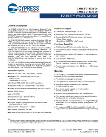
CYBLE-013025-00CYBLE-013030-00Figure 2. Module Mechanical Drawing[2, 3]Top View (See from Top)Side ViewBottom View (Seen from Bottom)Notes2. No metal should be located beneath or above the antenna area. Only bare PCB material should be located beneath the antenna area. For more information onrecommended host PCB layout, see “Recommended Host PCB Layout” on page 7.3. The CYBLE-013025-00 includes castellated pad connections, denoted as the circular openings at the pad location above.Document Number: 002-19200 Rev. *APage 5 of 41
CYBLE-013025-00CYBLE-013030-00Pad Connection InterfaceAs shown in the bottom view of Figure 2 on page 5, the CYBLE-0130XX-00 connects to the host board via solder pads on the backsideof the module. Table 2 and Figure 3 detail the solder pad length, width, and pitch dimensions of the CYBLE-0130XX-00 module.Table 2. Connection DescriptionNameConnectionsConnection TypePad Length DimensionPad Width DimensionPad PitchSP31Solder Pads1.02 mm0.71 mm1.27 mmFigure 3. Solder Pad Dimensions (Seen from BottomTo maximize RF performance, the host layout should follow these recommendations:1. Antenna Area Keepout: The host board directly below the antenna area of the Cypress module (see Figure 2 on page 5) mustcontain no ground or signal traces. This keep out area requirement applies to all layers of the host board.2. Module Placement: The ideal placement of the Cypress Bluetooth module is in a corner of the host board with the PCB traceantenna located at the far corner. This placement minimizes the additional recommended keep out area stated in item 2. Refer toAN96841 for module placement best practices.Figure 4. Recommended Host PCB Keep Out Area Around the CYBLE-0130XX-00 AntennaDocument Number: 002-19200 Rev. *APage 6 of 41
CYBLE-013025-00CYBLE-013030-00Recommended Host PCB LayoutFigure 5, Figure 6, Figure 7, and Table 3 provide details that can be used for the recommended host PCB layout pattern for theCYBLE-0130XX-00. Dimensions are in millimeters unless otherwise noted. Pad length of 1.27 mm (0.635 mm from center of the padon either side) shown in Figure 7 is the minimum recommended host pad length. The host PCB layout pattern can be completed usingeither Figure 5, Figure 6, or Figure 7. It is not necessary to use all figures to complete the host PCB layout pattern.Figure 5. CYBLE-0130XX-00 Host Layout (Dimensioned)Figure 6. CYBLE-0130XX-00 Host Layout (Relative to Origin)Top View (Seen on Host PCB)Top View (Seen on Host PCB)Document Number: 002-19200 Rev. *APage 7 of 41
CYBLE-013025-00CYBLE-013030-00Table 3 provides the center location for each solder pad on the CYBLE-0130XX-00. All dimensions are referenced to the center of thesolder pad. Refer to Figure 6 for the location of each module solder pad.Table 3. Module Solder Pad LocationFigure 7. Solder Pad Reference LocationSolder Pad(Center of Pad)Location (X,Y) fromOrign (mm)Dimension fromOrign (mils)1(0.39, 4.88)(15.35, 192.13)2(0.39, 6.15)(15.35, 242.13)3(0.39, 7.42)(15.35, 292.13)4(0.39, 8.69)(15.35, 342.13)5(0.39, 9.96)(15.35, 392.13)6(0.39, 11.23)(15.35, 442.13)7(0.39, 12.50)(15.35, 492.13)8(0.39, 13.77)(15.35, 542.13)9(0.39, 15.04)(15.35, 592.13)10(0.39, 16.31)(15.35, 642.13)11(0.39, 17.58)(15.35, 692.13)12(2.04, 18.82)(80.31, 740.94)13(3.31, 18.82)(130.31, 740.94)14(4.58, 18.82)(180.31, 740.94)15(5.85, 18.82)(230.31, 740.94)16(7.12, 18.82)(280.31, 740.94)17(8.39, 18.82)(330.31, 740.94)18(9.66, 18.82)(380.31, 740.94)19(10.93, 18.82)(430.31, 740.94)20(12.20, 18.82)(480.31, 740.94)21(13.47, 18.82)(530.31, 740.94)22(14.14, 16.31)(556.69, 642.12)23(14.14, 15.04)(556.69, 592.12)24(14.14, 13.77)(556.69, 542.12)25(14.14, 12.50)(556.69, 492.12)26(14.14, 11.23)(556.69, 442.12)27(14.14, 9.96)(556.69, 392.12)28(14.14, 8.69)(556.69, 342.12)29(14.14, 7.42)(556.69, 292.12)30(14.14, 6.15)(556.69, 242.12)31(14.14, 4.88)(556.69, 192.12)Document Number: 002-19200 Rev. *ATop View (Seen on Host PCB)Page 8 of 41
CYBLE-013025-00CYBLE-013030-00Module ConnectionsTable 4 and Table 5 detail the solder pad connection definitions and available functions for the pad connections for theCYBLE-013025-00 and CYBLE-013030-00 respectively. Table 4 and Table 5 lists the solder pads on the CYBLE-0130XX-00 modules,the silicon device pin, and denotes what functions are available for each solder pad.Table 4. CYBLE-013025-00 Solder Pad Connection DefinitionsUARTSPI[4]PadPad Name1XRESExternal Reset (Active Low)I2CADC2GND/NCGround/No Connect3GND/NCPWMCLK/XTALGPIOGround/No Connect (P11)PWM1(P27)XTALI32K(P11) PWM0(P26)XTALO32K(P12) 4P11/27[5]SPI2 MOSI (P27)(master/slave)5P12/26[5]SPI2 CS (P26)(slave) (P12))6P15SPI2 MOSI (P38)(master/slave) (P14/P38)PWM2(P14) (P13/P28)PWM3(P13)PWM2(P28) 7P14/38[5]8P13/28[5]9P24 PUART TX SPI2 CLK(master/slave)NCNot Connect11NCNot Connect12P25PUART RXSPI2 MISO(master/slave) 13P4PUART RXSPI2 MOSI(master/slave) 14P2PUART RXSPI2 MOSI (master)/SPI2 CS (slave) 15VDDPUART CTSSPI2 CLK(master/slave)P3SWDIO 1016OtherVDD (2.3 V 3.63 V) 17P8/33[5]No Connect (Used for on-module memory SPI interface for CYBLE-013025-00)18P32No Connect (Used for on-module memory SPI interface for CYBLE-013025-00)19P1PUART RTSSPI2 MISO(master/slave) 20P0PUART TXSPI2 MOSI(master/slave) 21SDAI2C SDA 22SCLI2C SCL 23UP TXUART TXD24UP RXUART CNot Connect30NCNot Connect31NCNot Connect Notes4. The CYBLE-013025-00 contains a single SPI (SPI2) peripheral supporting both master or slave configurations. SPI1 is used for on-module serial memory interface.5. The chip pin for this connection is dual-bonded. Use of the internal chip super-mux is required to configure the desired output signal on these connections.Document Number: 002-19200 Rev. *APage 9 of 41
CYBLE-013025-00CYBLE-013030-00Table 5. CYBLE-013030-00 Solder Pad Connection DefinitionsPadPad NameUARTSPI[6]I2CADC1XRESExternal Reset (Active Low)2GND/NCGround/No Connect3GND/NCPWMCLK/XTALGPIOOtherGround/No Connect (P11)PWM1(P27)XTALI32K(P11) PWM0(P26)XTALO32K(P12) 4P11/27[7]SPI2 MOSI (P27)(master/slave)5P12/26[7]SPI1 MISO (P26, Master)SPI2 CS (P26, slave) (P12))6P157P14/38[7]SPI2 MOSI (P38)(master/slave) (P14/P38)PWM2(P14) 8P13/28[7] (P13/P28)PWM3(P13)PWM2(P28) 9P24 PUART TX SPI1 MISO (master)SPI2 CLK (master/slave)SWDIO 10NCNot Connect11NCNot Connect12P25PUART RX13P4SPI2 MISO(master/slave) PUART RXSPI2 MOSI (master) PUART RXSPI2 MOSI (master)/SPI2 CS (slave) 14P215VDD16P3PUART CTSSPI2 CLK(master/slave)17P8/33[6]PUART RX(P33)SPI2 MOSI (P33) (slave)SPI1 CS (P33) (master) (P8/P33)ACLK1(P33) 18P32PUART TXSPI1 MISO (master)SPI2 CS (slave) ACLK0 19P1PUART RTSSPI2 MISO(master/slave) 20P0PUART TXSPI2 MOSI(master/slave) 21SDAVDD (1.62V - 3.63V) SPI1 MOSI (master)I2C SDA SP1 CLK (master)I2C SCL 22SCL23UP TXUART TXD24UP RXUART CNot Connect30NCNot Connect31NCNot Connect Notes6. The CYBLE-013030-00 contains two SPI peripherals, SPI1 and SPI2. SPI1 supports only master mode, whereas SPI2 supports masters or slave modes. Theconnections shown in Table 5 detail the SPI function for the given mode shown in parenthesis. If external memory is used with the CYBLE-013030-00, then SPI1should be used as the interface.7. The chip pin for this connection is dual-bonded. Use of the internal chip super-mux is required to configure the desired output signal on these connections.Document Number: 002-19200 Rev. *APage 10 of 41
CYBLE-013025-00CYBLE-013030-00Connections and Optional External ComponentsPower Connections (VDD)The CYBLE-0130XX-00 contains one power supply connection, VDD, which accepts a supply input range of 2.3 V to 3.63 V(CYBLE-013025-00) or 1.62 V to 3.63 V (CYBLE-013030-00). Table 14 provides these specifications. The maximum power supplyripple for this power connection is 100 mV, as shown in Table 14.It is not required to add any power supply decoupling or noise reduction circuitry on the host PCB. If desired, an external ferrite beadbetween the supply and the module connection can be included, but is not necessary. If used, the ferrite bead should be positionedas close as possible to the module connection. If used, the recommended ferrite bead value is 330 , 100 MHz.External Reset (XRES)The CYBLE-0130XX-00 has an integrated power-on reset circuit, which completely resets all circuits to a known power on state. Thisaction can also be evoked by an external reset signal, forcing it into a power-on reset state. The XRES signal is an active-low signal,which is an input to the CYBLE-0130XX-00 module (solder pad 1). The CYBLE-0130XX-00 module does not require an externalpull-up resistor on the XRES inputDuring power-on operation, the XRES connection to the CYBLE-0130XX-00 is required to be held low 50 ms after the VDD powersupply input to the module is stable. This can be accomplished in the following ways: The host device should connect a GPIO to the XRES of Cypress CYBLE-0130XX-00 module and pull XRES low until VDD is stable.XRES is recommended to be released 50 ms after VDD is stable. If the XRES connection of the CYBLE-0130XX-00 module is not used in the application, a 0.47-µF capacitor may be connected tothe XRES solder pad of the CYBLE-0130XX-00 to delay the XRES release. The capacitor value for this recommended implementationis approximate, and the exact value may differ depending on the VDD power supply ramp time of the system. The capacitor valueshould result in an XRES release timing of 50 ms after VDD stability. The XRES release may be controlled by a external voltage detection circuit. XRES should be released 50 ms after VDD is stable.Refer to Figure 10 on page 19 for XRES operating and timing requirements during power on events.Dual-Bonded GPIO ConnectionsThe CYBLE-013030-00 contains five GPIOs that are dual-bonded at the silicon level (four such pins exist on the CYBLE-013025-00).Solder pads 4, 5, 7, 8, and 17 are the module connections with dual-bonded silicon I/O. If any of these dual-bonded GPIO are used,only the functionality and features for one of these port pins may be used. The desired port pin should be configured in the WICEDSMART SDK. For details on the features and functions that each of these dual-bonded GPIOs provide, refer to Table 4 and Table 5.For additional information on all available GPIOs, refer to GPIO Port on page 22.External 32-kHz Clock/Crystal Oscillator InputThe CYBLE-0130XX-00 provides the option to connect an external 32-kHz crystal oscillator or clock input instead of using the internalLocal Oscillator (LO). Solder pads 4 and 5 of the CYBLE-0130XX-00 module provide this connection option. Note that these connections are also dual-bonded GPIOs, requiring the appropriate GPIO to be selected to enable external clocking functionality. The specificpins required are as follows: Module Solder Pad 4, Silicon GPIO P11 - Must be assigned as XTALI32K (Crystal Input terminal) Module Solder Pad 5, Silicon GPIO P12 - Must be assigned as XTALO32K (Crystal Output terminal)This option may be desired for customers who wish to achieve minimum power consumption in their application. Refer to 32-kHzCrystal Oscillator (Optional) on page 21 for details on the requirements for an external 32-kHz input to the CYBLE-0130XX-00.Using CYBLE-013030-00 with External FlashThe CYBLE-013030-00 does not contain any on-module nonvolatile memory. If desired, the CYBLE-013030-00 can be used with anexternal memory device (EEPROM or SFLASH). If EEPROM is used as an external memory device with I2C interface, module solderpads 21 (SDA) and 22 (SCL) must be used as the I2C interface.If using external SFLASH as the memory interface, SPI1 (master) must be used as the interface to the SFLASH device. The specificGPIO required and the applicable SPI signal is listed below. These are the same signals used for the SFLASH interface on theCYBLE-013025-00.1. SPI signal MOSI: Module Solder Pad 21, silicon GPIO SDA2. SPI signal MISO: Module Solder Pad 18, silicon GPIO P323. SPI Signal CLK: Module Solder Pad 22, silicon GPIO SCL4. SPI Signal CS: Module Solder Pad 17, silicon GPIO P8Document Number: 002-19200 Rev. *APage 11 of 41
CYBLE-013025-00CYBLE-013030-00Figure 8 illustrates the CYBLE-0130XX-00 schematic.Figure 8. CYBLE-0130XX-00 Schematic DiagramDocument Number: 002-19200 Rev. *APage 12 of 41
CYBLE-013025-00CYBLE-013030-00Critical Components ListTable 6 details the critical components used in the CYBLE-0130XX-00 module.Table 6. Critical Component ListComponentReference DesignatorDescriptionSiliconU132-pin QFN BLE Silicon Device - CYW20737SiliconU28-pin TDF8N, 128K Serial Flash (CYBLE-013025-00)CrystalY124.000 MHz, 12PFAntenna DesignTable 7 details the trace antenna used in the CYBLE-0130XX-00 module. For more information, see Table 7.Table 7. Trace Antenna SpecificationsItemFrequency RangeDescription2400–2500 MHzPeak Gain–0.5 dBiReturn Loss10 dB minimumDocument Number: 002-19200 Rev. *APage 13 of 41
CYBLE-013025-00CYBLE-013030-00Bluetooth Baseband CoreThe Bluetooth Baseband Core (BBC) implements all of the time-critical functions required for a high-performance Bluetooth operation. The BBC manages the buffering, segmentation, and data routing for all connections. It also buffers data that passes through it,handles data flow control, schedules ACL TX/RX transactions, monitors Bluetooth slot usage, optimally segments and packagesdata into baseband packets, manages connection status indicators, and composes and decodes HCI packets. In addition to thesefunctions, it independently handles HCI event types and HCI command types.The following transmit and receive functions are also implemented in the BBC hardware to increase TX/RX data reliability and securitybefore sending over the air: Receive Functions: symbol timing recovery, data deframing, forward error correction (FEC), header error control (HEC), cyclicredundancy check (CRC), data decryption, and data dewhitening.Transmit Functions: data framing, FEC generation, HEC generation, CRC generation, link key generation, data encryption, and datawhitening.Frequency Hopping GeneratorThe frequency hopping sequence generator selects the correct hopping channel number depending on the link controller state,Bluetooth clock, and device address.E0 EncryptionThe encryption key and the encryption engine are implemented using dedicated hardware to reduce software complexity and provideminimal processor intervention.Link Control LayerThe link control layer is part of the Bluetooth link control functions that are implemented in dedicated logic in the Link Control Unit(LCU). This layer consists of the Command Controller, which takes software commands, and other controllers that are activated orconfigured by the Command Controller to perform the link control tasks. Each task performs a different Bluetooth link controller state.STANDBY and CONNECTION are the two major states. In addition, there are four substates: page, page scan, inquiry, and inquiryscan.Adaptive Frequency HoppingThe CYBLE-0130XX-00 gathers link quality statistics on a channel-by-channel basis to facilitate channel assessment and channelmap selection. The link quality is determined by using both RF and baseband signal processing to provide a more accurate frequencyhop map.Document Number: 002-19200 Rev. *APage 14 of 41
CYBLE-013025-00CYBLE-013030-00Bluetooth Low Energy ProfilesThe CYBLE-0130XX-00 supports Bluetooth Low Energy (BLE), including the following profiles that are supported[8] in ROM: Battery status Blood pressure monitor Find me Heart rate monitor Proximity Thermometer Weight scale Time Alliance for Wireless Power (A4WP) wireless charging Automation profile Support for secure OTA (external memory required for CYBLE-013030-00)The following additional profiles can be supported[8] from RAM: Blood glucose monitor Temperature alarm Location Custom profileTest Mode SupportThe CYBLE-0130XX-00 supports Bluetooth Test mode, as described in the Bluetooth Low Energy specification.SecurityCYBLE-0130XX-00 provides mechanisms for implementing security and authentication schemes using: RSA (Public Key Cryptography) X.509 (excluding parsing) Hash functions: MD5, SHA-1, SHA-224, SHA-256, SHA-384, SHA-512 Message authentication code: HMAC MD5, HMAC SHA-1Note8. Full qualification and use of these profiles may require FW updates from Cypress. Some of these profiles are under development/approval at the Bluetooth SIG andconformity with the final approved version is pending. Contact your local representative for updates and the latest list of profiles.Document Number: 002-19200 Rev. *APage 15 of 41
CYBLE-013025-00CYBLE-013030-00ADC PortThe CYBLE-0130XX-00 contains a 16-bit ADC (effective number of bits is 10).Additionally: There are nine analog input channels in the 31
Fully certified module eliminates the time needed for design, development, and certification processes WICED SMART provides an easy-to-use integrated design environment (IDE) to configure, develop, and program a BLE application Pre-programmed EZ-Serial firmware platform to allow for


