Transcription
FiTech INSTRUCTION MANUALUltimate LS Systems - Kits 70001, 70002,70003, 70004, 70011, 70012, 70013 and 70014Fuel InjectionThis instruction manual is designed to get you up and running withyour Ultimate LS Induction System. This system is ready to go witheverything needed to complete the induction system of your LS engine and get you on the road easier and faster than any other systemon the market today. Suitable for your new or pull-out LS engines toensure you are up and running in a flash. For technical assistancewith your Ultimate LS System, call 951-340-2624 or go online towww.fitechefi.com under "tech center."Warning: Caution must be observed when installing any productinvolving fuel system parts or gas tank modifications. Work in awell ventilated area with an approved fire extinguisher readily available. Eye protection and other safety apparel should be worn to protect against debris and sprayed gasoline. Be sure to disconnect thenegative terminal of the battery before beginning. We recommendhaving this installation performed by an experienced, qualified, andFiTech approved automotive technician. The finished installationmust be thoroughly checked for any fuel system leaks. All safetyprecautions must be observed when working with fuel. Lastly, ensure the engine has had sufficient time to cool! The coolant maystill be hot. Disregarding any of this information can result in serious injury or death.Emissions Status:FiTech’s Ultimate LSSystem is not CARB(California Air ResourcesBoard) approved for useon emission controlledvehicles. This system isdesigned to control theEFI and ignition on LSbased engines beingretrofit into older vehicles that do not requireemission controls (pre1976).Dimensions and Hood Clearance Intake manifold is 6.5" tall as measured from the top surface of the block. The throttle body will clear any stock truck accessories depending on the type of water pump, if there istruck water pump accessory clearance interference you will need to get a new LS1 water pump and accessory bracket. The throttle body sits at at a downward angle of 7 degrees. Before installing your FiTech Intake manifold it is recommended to check hood clearance. This can be donein a few simple steps as follows: First, using modeling clay or putty, (not included), make several small cones about 2-3 incheshigh. Position the cones on the the various areas where you think clearance might be tight. Close the hood to locked position and re-open. The height of the cone indicates the space between the hood and the air cleaner. Record these measurements. We recommend 1" of clearance. Modification of the hood might be necessary to ensure there is no damage to any components.Table of ContentsEmissions StatusDimensions & Hood ClearanceParts Required Not IncludedKit Contents 500 HPKit Contents 750 HPModified EnginesFeaturesEngine Protection FeaturesSpecial InstructionsInstalling the ManifoldInstalling the Throttle BodyInstalling the Fuel RailsWiring SystemsWiring DiagramVSSMain PowerAccessory Wires11122333345566777Wiring Diagram (Continued)Red WireOrange WireTrans ControlFuse BoxCoil DCoil PKnockINJ PINJ DCKPCAMALTCTSIATMAPIAC7777778888888999Wiring Diagram (Continued)TPSFinal StepsInitial ProgrammingHandHeld ControllerTiming ControlRev LimiterOn-Engine AdjustdmentsPower AdderCrank SensorCam SensorWide Bend Oxygen SensorTransmission ControlFuel Pump Pulse Width ModulationAir/Fuel RatioWarrantyFiTech EFI Contact Information99910101010101010111111111212Parts not included in the kit:1. Coil Packs2. Fuel Delivery System suitable to support required HP.3. Optional Throttle Cable Bracket (FiTech #67001)4. CAM Extension Cable is not included in 70001 or 70051.5. Coil Pack Sub-harnesses are not included.1
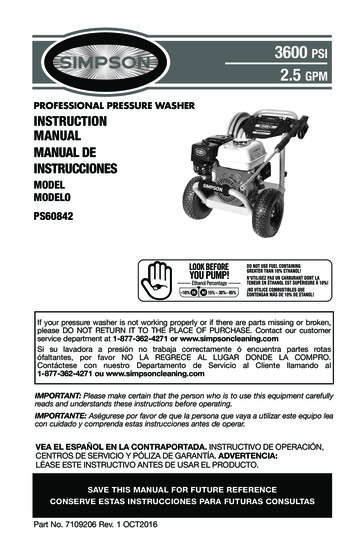
Figure 1500 HP KitContentsContents for 500 HP Ultimate LS Kit92MM Billet Aluminum Throttle BodyHandHeld Controller and cableWindshield mount for HandHeld controller(8) 36 lb/hr InjectorsLS ECUFabricated Aluminum Intake Manifold and boltsPlug and Play Primary Wiring Harness3 BAR MAP SensorThrottle Position Sensor (TPS)Idle Air Control Motor (IAC)Inlet Air Temperature Sensor (IAT)Wide band Oxygen SensorStainless Steel Oxygen Sensor Bung KitHigh Volume Fuel Rails including:Mounting brackets-6 AN fittings(2) Fuel RailsScrews for Mounting BracketsAN fittings and Fuel Crossover Hose AssemblyFigure 2750 HP KitContentsContents for 750 HP Ultimate LS Kit102MM Billet Aluminum Throttle BodyHandHeld Controller with color touch screenWindshield Mount for HandHeld Controller(8) 55 lb/hr Injectors(1) LS ECUFabricated Aluminum Intake Manifold and boltsPlug and Play Wiring Harness3-BAR MAP SensorThrottle Position Sensor (TPS)Idle Air Control Motor (IAC)Idle Air Temperature Sensor (IAT)(2) Wide band Oxygen Sensor(2) Stainless Steel Oxygen Sensor Bung KitsHigh Volume Fuel Rails including:Mounting brackets-6 AN fittings(2) Fuel Rails RailsScrews for Mount BracketsAN fittings and Fuel Crossover Hose Assembly2
Modified EnginesThe Ultimate LS intake manifolds are designed to provide maximumperformance for street/performance engine applications. The intakemanifold will have the best fitment when the engine block and cylinder heads are machined to standard OE dimensions. If the engineblock or cylinder head deck surfaces have been milled significantly,the alignment of the mounting bolt holes and the port flange openings to the cylinder head may be shifted and not match up satisfactorily. If your engine has had the cylinder heads or engine block decksurfaces milled, the following may be necessary for proper intakemanifold installation. The bolt holes in the intake manifold wouldhave to be slotted to allow the fastener to properly pass through themanifold mounting holes. The mounting fasteners must freely threadinto the cylinder head while passing through the mounting holes oroverture . thethe manifold may not seat properly onto the cylinder head surfaceswhen the fasteners are tightened. As the o-ring grooves are locatedin the intake manifold mounting flanges, material may not be removed from the intake manifold mounting flanges without jeopardizing the sealing of the manifold. Any material removal required toalign the port flange openings should be removed from the cylinderhead not the intake manifold. When port matching the intake manifold port openings to the cylinder head openings, care should betaken not to break into or damage the o-ring groove or o-ring sealwill not be effective. The intake manifold mounting surfaces on thecylinder heads should be in good condition, and free of nicks orscratches, where the sealing o-rings will seat on the heads to ensureproper sealing.FeaturesFiTech Ultimate LS Induction System is designed for street and performance engine applications with a 1500-6500 rpm power-band.The Ultimate LS kits are designed to support either 500 hp or 750hp to the flywheel and all kits include a 3 BAR MAP sensor for poweradder applications that support up to 30 PSI of boost (3 BAR). It hasa high-flow cable operated 92mm or 102MM inlet throttle body and36 lb or 55 lb flow-matched injectors. The 92mm and the 102 mmthrottle bodies have parabolic inlet machining for smooth throttletransitions which is the same as OE throttle bodies. The throttle bodyfeatures a progressive linkage pulley with a double return spring andan adjustable stop.The 500 hp and the 750 hp kits are both availablewith a transmission control option. The manifolds are designed witha 3mm thick construction that is TIG welded, black anodized withembossed FiTech logo and CNC machined with o-ring gasket and either cathedral or square port applications. The kit comes with a selflearning ECU with touch screen controller for easy setup and con-figuration. The programmable color touch screen HandHeld Controller includes a data logging feature. The Ultimate LS kit has a sequential fuel and spark control with individual cylinder trim.The system also comes with stainless steel oxygen sensorbung(s), target AFR and timing control if desired, two fan controloutputs, 5V tach output driver for most tachometers and aspeedometer output driver for most electric speedometers. The system is compatible with 24X and 58X crank sensors, LS1-LS3 camsensors, and compatible with car and truck coils.Wiring the system is made easy with a custom wiring harnessthat uses existing factory coil packs and sub harnesses. FiTech's Ultimate LS kit comes with a knock sensor control and is custom camfriendly. Included are several timing curves that are each tailored fordifferent camshafts, final drive gearing, and vehicle weight. The Ultimate LS system will allow for both EV1, EV6, and truck injectorswith interchangeable injector harnesses. (Not included)Engine Protection FeatureThe FiTech Ultimate LS Induction System is programmed with a limphome mode. Our features differ from competitors because the FiTechunit will not shut down your system. Instead the ECU will compensate if a sensor fails. This means, that if for any reason a sensor fails,that sensor will receive either a default value or a simulated value.This is to ensure that the engine remains running in a safe and controlled manner so that you can get to a repair facility, or to your hometo resolve the issue. Due to the compensation features of the ECU,the way to check if something is going wrong with your system isthe blah blah blaah blah.byby the fault codes option on the main menu of your hand-held controller. The fault code comes up under OBD-II, diagnostic standard,to the right of the code it will state which sensor is having the problem. Check our troubleshooting guide to solve the fault codes errors.A new feature programmed into our hand-held is a rev offset. Thisfeature will protect the engine because it lowers your built in rev limiter to prevent over rev and possible engine damage during warmup. It will automatically turn the feature off once your engine reachesoperating temperature.Special Instructions We recommend using either the FiTech G-surge, or the FiTech HyFuel In-tank Retrofit Kit setup for optimum fuel delivery for all installations. A submerged pump is quieter and lasts longer. If using the Frame Mount Inline Fuel Pump, it should be mountedat, or below, the bottom level of the fuel tank and as close to the tankas possible. No more than 3-feet away from the tank. This type ofpump is designed to pump, not draw. Works best when gravity fed. Only use hard fuel lines when using proper EFI rated flared fittings. Do not use solid core ignition wires. Make sure that you remove ALL low pressure flex joints on factoryfuel lines and replace them with EFI rated fuel hose and use properflared connections and clamps. Be careful not to mix 45 and 37 AN fittings. They look similar but will not work together. 45 fittingsusually come from a hardware store or auto parts store while 37 AN fittings are what is supplied by FiTech and most speed shops. Inline fuel pump return line must be -6 hose. Only the steady state fuel “learns”. Cranking and hard throttle hitswill not learn, but they can be tuned in Go-EFI Tuning. Selecting theright “cam” and engine CID (cubic inch) will get the learning closer.The Accel Pump will often need tuning for your particular enginecombination. Your system needs to run at 58 PSI so consult a FiTech approvedprofessional if you are not certain about this portion of your installation. FiTech does not recommend aluminum fuel lines EVER! Use the supplied push lock style hose ends only with the suppliedhose and vice versa. Interchanging hose ends and hose with otherbrands could cause leaks. The Ultimate LS systems are intended for use with unleaded pumpgas with up to 15% ethanol content.3Continued next page
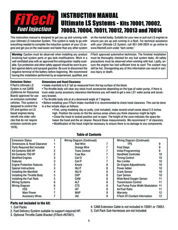
Special Instructions (Continued): Tach output driver provides a 5V output signal. The fuel rails are machined to receive the supplied adapter fittingsfor -6 ORB to -6 AN male o-ring port. It is recommended to use unleaded fuel to ensure a longer lastingoxygen sensor. Leaded fuel will lead to improper exhaust gas oxygenreadings. Before starting the install, ensure any RTV silicone sealerused is sensor compatible. This information can be found on the RTVpackage. When installing the fuel rails hardware and brackets, it is importantto only hand tighten a couple of threads in place, then once all boltsand hardware are in place, tighten the brackets to the rail beforetightening the rail to the manifold. Be sure the engine has had sufficient time to cool before startingwork on the installation. Be sure to disconnect the negative terminal of the battery beforebeginning.Very important note: Your fuel tank must have a vent to preventpressure building up inside the tank.Installing the Intake Manifold1. Before starting the installation, disconnectthe negative battery terminal (ground).2. Before installing the intake manifold, set theintake on the cylinder heads to test fit the intakemanifold without the o-rings installed. Makesure that the mounting bolts supplied canthread freely into the cylinder heads throughthe intake manifold mounting holes and thatthe mounting flange seats properly. Check theport opening alignment and test fit the throttlebody, fuel and vacuum plumbing, throttle linkage, wiring, etc to ensure there are not any fitissues before performing the final intake manifold installation.Figure3Figure 5Figure 43. Install the MAP Sensor to back of manifold as shown in the photoat right. Then thread the Air Temperature Sensor into the front of themanifold and tighten securely. See Figure 7 on next page.Note: Torque specs are in inch pounds, not foot pounds.TORQUE SPECIFICATIONS FOR LS ENGINES10624873159Make first pass, following sequence shownhere, torquing to 44 lb.in. Then make secondpass torquing in sequence to 89 lb.in. Retorque after the engine reaches operatingtemperature, in sequence, to 89 lb.in.44. Now install the eight o-rings provided in the mounting flange oring grooves. Apply a small amount of grease to the o-rings to ensure proper seal and help hold them in position during installation.5. Next, place the intake manifold onto the cylinder heads, beingcareful that the o-rings remain in the grooves and are not beingcrushed between the manifold and the cylinder heads.6. Apply a small amount of engine oil to the threads of the bolts before installing themFigure 6into the intake.7. Then install thebolts and washersand tighten following the torque sequence shown in thechart at left.
Installing the Throttle BodyFigure 71. If optional Throttle Cable Bracket (FiTech #67001) isused, position it between the manifold and throttle bodywith gasket on the front face and the supplied o-ring inthe groove on the manifold. See Figure 7.2. Attach the Idle Air Control (IAC) and Throttle PositionSensor (TPS) to the new throttle body. Make sure eacho-ring is in the groove and does not slip out while installing.3. Tighten the screws holding the IAC and TPS to thethrottle body.4. Make certain the gasket mating surface on the intakemanifold is clean and free of debris.5. Using the included bolts, attach the throttle body to theintake manifold. Tighten bolts securely.6. Slip the throttle cable on the linkage arm.7. Observe the throttle body (while an assistant pressesand releases the gas pedal) to ensure that the throttleblade opens and closes while also operating smoothly.Installing the Fuel RailsAir TemperatureSensorFigure 81. Before installing the fuel rails, apply light grease to theo-ring on both ends of the fuel injectors (Figure 9) andinsert the fuel injectors into the ports in the fuel rail (Figure 10).2. To insert the injector without tearing the o-ring, gentlyrock the injector in the inlet of the port while applyingpressure to insert the injector.3. Insert the injector with its connector facing towards theoutside of engine into the fuel rail.4. Continue with the other three injectors. With the injectors installed, it is time to install the fuel rail assembly tothe engine.5. Position the rail assembly over the intake manifold withthe injectors aligning with their mounting pockets on theintake.6. With the injectors lined up, lightly press down on thefuel rail using caution not to bind any of the injectors orconnectors. See Figure 11. The fuel rail assembly shouldcome close to contacting the manifold brackets with verylittle pressure. Use caution not to bind or tear any injectoro-rings. Check and ensure the injector is floating on theo-rings; rotate the injector back and forth to confirm thatthere is no bind on the injector body.7. Attach the fuel inlet fittings to the front ports of the fuelrails. Make sure o-ring is on the end of thefitting that threads into the fuel rail. SeeFigure 12. Now install the crossover hose.Figure 9Figure 10Figure 11Fuel System Requirements1. System must have 30 microns or better fuel filtration.2. Must be capable of supplying 58 PSIof fuel pressure to the injectors under fullload.3. Must use 37 flare fittings on all fuelline connections.5Figure 12
Wiring the SystemThe Ultimate LS kit makes wiring the harness very simple. Every connection in the harness is labeled for where it goes.The various wireswill need to be extended to make required connections. See the wirechart below which lists each wire used in the system and what it connects to. It is strongly suggested that any wire extensions are madewith the same gauge and color wire as is used in the supplied har-20Figure 1311615172223121310ness. Make connections as a soldered joint rather than a crimpedconnection. Utilize a shrink wrapped sleeve covering all connections.All modifications to wiring must be made on Item 3 "AccessoryWires," (the vehicle side wiring) such as extensions or cuts. Anymodification of the ECU side harness will result in a VOIDED warranty.Connector1819212162Main Power: Positive 12V goes to starter.POS (Red)Needs to be live even with power off.3These wires go to Fan, Tach Out, A/C Kickup,Accesory WiresSpeedometer, & Torque Converter Brake Switch4On/Off - Connect to switched 12V circut. MustRed Wire (Key)be on during "Key On" and "Cranking."5Fuel Pump circuit. Wire provides 12V to fuelOrange Wirepump. Connect to ( ) terminal on pump.6One grounds the ignition and one grounds toGroundsthe engine block.7Only used when using transmission control.Optinal second O2 on passenger side. YellowO2 Harness connector.6-pin.9Fuse Box with Relays.Fuse Box10O2 Sensor on driver's side.DRV.02175Vehicle speed sensor connects to back oftransmission output.Two Trans Connectors691VSS814Location8Passenger side coil pack connection. Coils andand coil pack sub harnesses not supplied.12Driver side coil pack connection. Connects toCoil Duniversal connector on O.E. coil pack.13Use sub-harness extension to reach to LS2,KnockLS3 on side of block. LS1 is on back of block.14Passenger side injector harness.INJ P15Driver side injector harness.INJ D24311Coil P16Crank position sensor. Located between starterCKPand engine block.17Use extension for LS2, LS3 where cam con-CAMnects to front. LS1 connects to back.18Connects directly to the alternator.ALT4619Connects to engine coolant temperature sensorCTSon driver's side front of cylinder head.20Intake air temperature. Connects to front driverIATside of manifold. Threads into manifold.21Connects to MAP sensor on back of theMAPmanifold.22Idle Air Control. Connects to IAC mounted onIACthe throttle body.23Connects to throttle position sensor mountedTPSon the throttle body.24Connect the two female connectors to the twoHandHeld Controllermale connectors on the Handheld harness.
Main Wiring Harness Connection DetailsVSS: Vehicle speed sensor connects to back of trans output.Ground: The wiring harnesscontains two ground wires(Ignition and ECU low currrent). They can be attachedto existing threaded holes inthe back end of both cylinderheads. One ground
embossed FiTech logo and CNC machined with o-ring gasket and ei-ther cathedral or square port applications. The kit comes with a self learning ECU with touch screen controller for easy setup and con-figuration. The programmable color touch screen HandHeld Con - troller includes a dat