Transcription
Quick Start GuideTMXDS-PR0 SERIESThis quick start guide applies to XDS-PRO4Q and XDS-PRO1Q receivers.1. Important Guidelines review this guide in its entirety before installing your XDS-pro receiver. FOLLOW THESE INSTRUCTIONS BEFORE CALLING SUPPORT. REVIEW ATTACHED NETWORK CONFIGURATION DATASHEET -THIS RECEIVER IS PRE CONFIGURED AS SPECIFIED IN THE ATTACHED NETWORKCONFIGURATION DATASHEET. IF THE NETWORK CONFIGURATION DATASHEET DOES NOT HAVE CONFIGURATION VALUES YOU MUST CONTACT YOURUPLINK SERVICE PROVIDER NETWORK TO ACQUIRE THE SATELLITE TUNING DETAILS: L-BAND FREQUENCY, SYMBOL RATE, AND WEB ADDRESS OF THEAFFILIATE WEBSITE. YOUR NETWORK MAY REQUIRE THAT THIS RECEIVER BE CONNECTED TO THE INTERNET (PLEASE SEE NETWORK CONFIGURATION DATASHEET). IN THATCASE, THIS RECEIVER WILL NOT RECEIVE NETWORK PROGRAMMING UNTIL YOU CONNECT IT TO THE INTERNET AND ACTIVATE IT PER THE INSTRUCTIONSIN THIS DOCUMENT. MAKE ALL SATELLITE RF, DATA (LAN/WAN), AND AUDIO CONNECTIONS PRIOR TO APPLYING AC POWER TO THE XDS RECEIVER. USE AN UNINTERRUPTIBLE POWER SUPPLY (UPS) TO PROTECT THE RECEIVER FROM POWER SPIKES AND BROWNOUTS. IF YOU ARE LOCATED INAN AREA SUSCEPTIBLE TO FREQUENT LIGHTNING STORMS, PLEASE ALSO CONSIDER LIGHTNING SUPPRESSORS. MANY UNINTERRUPTIBLE POWERSUPPLIES ARE NOT RATED TO PROVIDE SUFFICIENT PROTECTION FOR LIGHTNING STRIKES. THERE ARE NO USER ADJUSTABLE SWITCHES, JUMPERS OR CONTROLS INSIDE THE UNIT ITSELF, SO DO NOT OPEN THE UNIT. OPENING THE UNIT ANDBREAKING THE WARRANTY LABEL WILL RESULT IN A VOID OF THE WARRANTY. APPENDIX A AT THE BOTTOM OF THIS DOCUMENT CONTAINS A FRONT PANEL MENU MAP THAT CAN HELP YOU NAVIGATE THROUGH THE XDSRECEIVER SETTINGS AND CONFIGURATION.For more details on configuration parameters for the XDS-PRO Series Receivers please consult the relevant chapters in the User Manual using the linkprovided by your Affiliate Web Site.2. PREPARING FOR INSTALLATION2.1 UnpackingInspect the carton upon receiving and note any damage to the carton for possible unit damage. Carton includes: The XDS-PRO Receiver XDS-PRO Quick Start Guide Network Configuration Datasheet containing RF Settings and technical support contact information.Carton may include the following optional items: An optional cable kit containing mating DB-37 connectors with shells (1 – PRO1, 2 – PRO4), mating DB-9 connectors with shells(1 – PRO1, 4 – PRO4), RF cable, LAN cable, and RF splitter. CD with complete documentation. Documentation including User Manual is also available for download at your Affiliate’s Web Site.2.2 Rack MountingThe unit is designed for installation in an EIA standard 19-inch (480 mm) equipment rack. Use pan or round head screws and soft washers in all fourFront Panel mounting locations.2.3 Downloading/Installing the XDS Discovery ToolThe XDS Discovery Tool is a software application that helps discover XDS-PRO receivers in the local network (LAN) to help in the configuration process.This tool is intended to help configure XDS-PRO receivers that DO NOT HAVE a front panel.Please see the included Network Configuration Data Sheet for the URL to download the X-Digital Systems Receiver Discovery Tool. This URL containsinstallation instructions, a download link for the installer, usage instructions, and a quick start guide for the XDS Discovery Tool. This tool can also befound under the Help tab of the Affiliate website.R830002-2001 REV A1
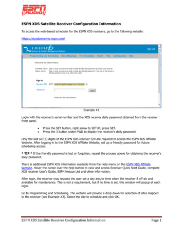
Quick Start GuideTM3. Connecting your Receiver3.1 Satellite RF ConnectionYour XDS-PRO receiver is preconfigured to tune itself to the settings specified in the attached Network Configuration Data Sheet. Once the RFconnection from your downlink is properly connected and you apply AC power, the receiver should automatically tune and lock to the network carrier.If the Network Configuration Datasheet does not include a specific network, you must contact your uplink service provider network to acquire thesatellite tuning details: L-band frequency, symbol rate, and web address for the affiliate website.3.1.1 CablingWhen connecting your receiver we recommend using RG-6 and that the splitter is rated for L-Band frequencies (950-2150 MHz). Use of lower ratedequipment can result in roll off and significantly degraded signal quality. Your receiver may include an optional cable kit with these connectors.3.1.2 LNB VoltageYour receiver was shipped from the factory with the LNB voltage disabled by default. If you need the receiver to drive the LNB on your dish, you canenable it after you have powered it up from the Tuner Setup section of the front panel. Please see Appendix A for details. If you have a XDS-PROreceiver without a front panel, you can enable it after you have powered it up and connected to the web interface. Please see section 4.2.2 for details.3.2 Internet ConnectionYour network may require that the XDS-PRO receiver is always connected to a broadband connection (Internet). The broadband connection is usedby the network to remotely troubleshoot, send content to the internal storage, send commercial playback schedules, retrieve as-played logs ofcommercial insertions, and stream live audio to the receiver.3.2.1 Connecting the Receiver to your LANIf you elect to place the receiver on your local network inside of your firewall, you will connect a patch cable from your internal switch or router to theport labeled LAN-1. The receiver is set by default to obtain an IP address via DHCP. If your network does not have a DHCP server, you will need toassign it a static address through the front panel. Please see section 4.2.3 for details on manually assigning IP addresses.3.2.2 Connecting the Receiver to the WANIf you would like your receiver to access the internet directly through a DMZ connection or outside of your firewall, you will connect a patch cable tothe port labeled LAN-2 on the back of the receiver. Since main management method for the XDS-PRO receiver is the web interface, X-Digital Systemsdoes not recommend connecting it solely to the WAN. In general, access to the receiver from a PC in your LAN will be blocked if the receiver is in aDMZ zone or outside of your firewall. To assign a static IP address to the WAN, please see section 4.2.2.3.3 Connecting the Audio PortsThe analog audio output of the XDS-PRO receivers is routed through the DB-9 connector labeled Audio-A through Audio-D on the rear panel. Thetable below details the wiring pin out for the ports:PinSignal1L OUT 2Ground3L OUT (*)4Ground5R OUT 6L OUT-7Ground (*)8L OUT- (*)9R OUT-(*) - These additional output pinsare provided for StarGuide receivercompatibility.Optional cable kit may include four matingDB-9 connectors with shells. Please seethe XDS-PRO User’s Guide for detailedspecifications on the audio output.3.4 Relay ClosuresThe XDS-PRO4 receiver has two DB-37 connectors labeled Relay-A and Relay-B on the rear panel. The XDS-PRO1 receiver has one DB-37 connectorlabeled Relay-A. These connectors contain sixteen relay/contact closures that can drive external automation systems. The tables below detail the pinout for the ports:R830002-2001 REV A2
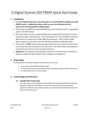
Quick Start GuideTMRelay A – DB37MRelay B – Relay 1A20Relay 1B1Relay 1A20Relay 1B2Relay 2A21Relay 2B2Relay 2A21Relay 2B3Relay 3A22Relay 3B3Relay 3A22Relay 3B4Relay 4A23Relay 4B4Relay 4A23Relay 4B5Ground24Ground5Ground24Ground6Relay 5A25Relay 5B6Relay 5A25Relay 5B7Relay 6A26Relay 6B7Relay 6A26Relay 6B8Relay 7A27Relay 7B8Relay 7A27Relay 7B9Relay 8A28Relay 8B9Relay 8A28Relay 8B10Ground29Relay 9B10Ground29Relay 9B11Relay 9A30Relay 10B11Relay 9A30Relay 10B12Relay 10A31Relay 11B12Relay 10A31Relay 11B13Relay 11A32Relay 12B13Relay 11A32Relay 12B14Relay 12A33Ground14Relay 12A33Ground15NC TxData34Relay 13B15Ground34Relay 13B16Relay 13A35Relay 14B16Relay 13A35Relay 14B17Relay 14A36Relay 15B17Relay 14A36Relay 15B18Relay 15A37Relay 16B18Relay 15A37Relay 16B19Relay 16ANANA19Relay 16ANANAIf your automation system can read text cues directly, the cue serial stream is available from Relay Port A pins 15 and 10 (GND). The NC TxData pin isRS-232 data with no flow control or handshaking. By default, the baud rate is set to 9600 bps, eight data bits, no parity, and one stop bit.Optional cable kit may include one or two mating DB-37 connectors with shells. Full electrical specifications for the relay closures can be found in theXDS-PRO User’s Guide.3.5 Locating the Receiver on Your NetworkThis section is required for those who have an XDS-PRO1 receiver with no front panel LCD.Begin by downloading, installing, and launching the Discovery Tool to a PC residing in the same network as the receiver. Once it has opened, click theStart button at the top to begin scanning your local network. As it finds receivers on your network, it will populate the results in the grid below. Youmay see multiple results returned if you have other XDS satellite receivers on your network. Look for a receiver that has PRO1 in the receiver typefield and a serial number matching the unit you just installed. Once your unit is located, click on the IP address in the first column to launch the webinterface in your default browser. At the login prompt for the web interface, please login with the following credentials:User: techPassword: radioNote: If your unit does not show up in the list or if you do not have a DHCP server on your network, you will need to follow the steps in Appendix A atthe end of this guide before proceeding.4. Verification of FunctionalityOnce all of the connections have been made, you may connect AC power to the receiver and begin verification of the receiver functionality.4.1 Verify the Receiver is Tuned and Locked to the Network CarrierOnce the satellite is properly connected and the receiver is powered up the receiver is configured from the factory to tune and lock to your network’scarrier. Please verify as follows:R830002-2001 REV A3
TMQuick Start Guide4.1.1 Acquiring LockIf your XDS-PRO receiver does not automatically lock and/or to verify the correct network satellite settings, you will need to use the front panel controlsor the web interface on XDS-PRO receivers with no front panel controls.4.1.1.1 Using Front Panel ControlsQuick verification of the tuner status can be done from the front panel of the receiver. If the green LED labeled as Signal is lit, the receiver is lockedto a satellite carrier. However, this does not guarantee that the receiver is locked to the correct carrier. You can navigate to the Tuner section of thefront panel to verify that the frequency and symbol rate match the values specified in the included Network Data Sheet. Additionally, you can manuallychange the value here if your receiver does not automatically lock. At the main screen with the network logo, press the SET key, then the left or right arrow keys to reach Setup. Press SET.Press the left or right arrow keys to reach Tuner. Press SET.Press the left or right arrow keys to reach Frequency. Press SET.Check Network Data Sheet for FrequencyUse the four arrow keys and the SET key to set the frequency to the value on the Network Data Sheet packed with your receiver.Press the left or right arrow keys to reach Symbol Rate. Press SET.Check Network Data Sheet for Symbol RateUse the four arrow keys and the SET key to set the symbol rate to the value on the Network Data Sheet packed with your receiver.4.1.1.2 Using Web InterfaceOnce logged in to the web interface, you will be on the Status tab of the General page. Click on the Tuner tab to view the current tuner settings andstatistics of the receiver. On this page you will be able to see the frequency and symbol rate. If the settings do not match the values in the NetworkConfiguration Data Sheet, click the Edit Tuner Settings button at the bottom of the tab. You will now be able to edit the applicable tuner settings foryour carrier as well as enable the LNB power if the receiver is designated to supply DC voltage to your dish. After you are finished making changes,click Save Tuner Settings.4.1.2 Signal QualityOnce the tuner is locked and the correct carrier is verified, the quality of the signal should be verified to ensure reliable service. On the startingscreen of the front panel or in the web interface the receiver displays the Eb/N0 (shown as EB) and AG (automatic gain shown as AG) values from thetuner. The EB value should be above 7 and AG should fall between 40 and 60. If your values do not fall within these ranges, please verify proper dishorientation and RF wiring.4.2 Verify IP Connectivity to the NOCIn order for the NOC to send programming and schedule information to your receiver, it must be able to communicate with the receiver over theinternet.4.2.1 NOC Connection Test Using Front Panel ControlsUnder the Network Setup section of the front panel there is a tool called Test NOC that will allow you to verify internet connectivity to the NOC. Pressthe 2 softkey that is labeled NOC to initiate the test.After the test completes you will either see ‘Successfully Connected to NOC’ or ‘Cannot Connect to NOC!’ If your receiver is able to connect, yoursettings are correct and you are ready to proceed with the next tests. On the other hand, if your receiver is unable to connect, you will need to adjustyour IP settings until the test is successful. You may need to check settings on the receiver or in your network including any switches, routers orfirewalls. The receiver will need to be able to communicate on TCP port 80 to the internet. Please see the next section if you need to assign thereceiver a static IP address or configure a proxy server.4.2.2 NOC Connection Test Using the Web InterfaceOn the General page of the web interface under the Status tab there is a tool named the NOC Connection Test that will allow you to verifyconnectivity to the NOC. Click the Initiate Test button and then confirm you want to start the test by clicking Begin Test.The test should take no longer than a minute or two but during this time the web interface will be unresponsive to other commands. After the testcompletes you will either see ‘NOC Connection Successful’ or ‘Cannot Connect to NOC.’ If your receiver is able to connect, your settings are correctand you are ready to proceed with the next tests. On the other hand, if your receiver is unable to connect, you will need to adjust your IP settings untilthe test is successful. You may need to check settings on the receiver or in your network including any switches, routers or firewalls. The receiver willneed to be able to communicate on TCP port 80 to the internet. Please see the next section if you need to assign the receiver a static IP address orconfigure a proxy server.R830002-2001 REV A4
TMQuick Start Guide4.2.3 Assigning a Static IP Address Using Front Panel ControlsAssigning a static IP address to either the LAN or WAN can be done from the Network Setup section of the front panel. This section allows DHCP tobe toggled, a gateway to be specified, a static IP address to be set for the LAN or WAN port, or an HTTP proxy server and port to be specified. Whenspecifying IP addresses, use the Up/Down keys to adjust the numerical values and the Left/Right keys to move between octets. The SET key willsave the specified address. Once all adjustments are complete, run the TEST NOC again to make sure the receiver is able to successfully connect tothe NOC. Please see Appendix A for help on navigating through the front panel menus.4.2.4 Assigning a Static IP Address Using the Web InterfaceAssigning a static IP address to either the LAN or WAN can be done on the General page of the web interface under the Setup tab. Click on EditConfiguration Settings at the bottom of the tab to make adjustments. The TCP/IP Networking section allows DHCP to be toggled, a gateway to bespecified, a static IP address to be set for the LAN or WAN port, or an HTTP proxy server and port to be specified. Once all adjustments are complete,click Save Configuration Settings. Please note that if you changed the IP address of the receiver you will need to navigate to the new address in abrowser to reconnect to the web interface.4.3 Verify Audio ReceptionOnce the receiver is locked to the network carrier, you can verify audio functionality as follows:4.3.1 Verify Audio ReceptionFrom the factory your receiver is configured to play out the Test Channel for your network on all audio ports, however, your network may ship thereceiver with current programming and authorizations active. Even if this is the case, the Test Channel can be used to verify audio reception as well asverify proper wiring to the rear DB-9 connector.The Test Channel is intended to check receiver operation; it does NOT indicate thatyou can receive regular network programming. You must complete all installation andactivation steps including a fulltime internet connection to receive program audio. YourXDS-PRO receiver must ALWAYS be connected to the internet.4.3.2 Verify Audio PortsEach DB-9 audio connector carries one radio program stream, either mono or stereo. If the program is mono, the same audio appears on the left andright pin pairs. In most cases, the left and right sides of a stereo channel are no longer used to carry unrelated mono programs.To manually program the XDS-PRO receivers to output the Test Channel on a desired audio port: At the main screen with the network logo, press the SET key, then the left or right arrows to reach Audio Ports. Press SET.Press the left or right arrows to select the Audio Port (letter A, B, C or D). Press SET.Press the left or right arrows to select Program. Press SET.Use the up and down arrows to find the Test Channel. Press SET.Verify that you can hear the Test Channel through all receiver ports.5. Verification of Programming and ActivationYou can edit and activate the programming schedule of your receiver through the Affiliate website of your network. The URL for this site is provided onthe Network Data Sheet.To login you will use the serial number of your receiver as the username and a password generated by the receiver. The password can be found asfollows: On the front panel in the Setup section where the serial number is displayed press the 3 soft key to show the daily password.Or the web interface in the General section find and click the Show Daily Login and Password.Use this password along with your receiver serial number to log in to the Affiliate websiteR830002-2001 REV A5
TMQuick Start Guide5.1 Setup From the Affiliate WebsiteOnce logged in to the Affiliate website, the following adjustments should be made prior to activation:a. Set a friendly password: This will be a persistent password that will allow you to log in to the site without finding the daily password each dayb. Adjust Time Zone: In addition to the proper time zone for your location, please make sure your daylight savings settings are correctc. Review Schedule: In the XDS system each program, not each channel, is permissioned and labeled for station use. Therefore, instead oftuning to a channel to find a program, you will schedule the programs to appear on each output port based on the stations that have receivedauthorization(s). You will need to review your schedule before activating your receiver. For detailed instructions on using the scheduler, please seethe XDS-PRO User’s Guide.Note: This receiver is equipped with digital storage that allows a ‘tape delay’ of live network programming per your affiliate agreement. You can usethis capability to schedule your receiver with a combination of live and delayed programming. The User’s Guide contains a full explanation of theschedulerd. Review Relay Mappings: The receiver will be preconfigured by the network with the default relay mappings. Please review and modify asdesired to connect the receiver with your automation equipment.e. Approve Setup and Activate: Once you have reviewed all of the settings above, press the Update button. Within a few minutes, the NOC willsend the updated programm
3.1 Satellite RF Connection Your XDS-PRO receiver is preconfigured to tune itself to the settings specified in the attached Network Configuration Data Sheet. Once the RF connection from your downlink is properly connected and you apply AC power, the receiver shoul