Transcription
Configuring a Cisco ASA 5505December 2008Rob Denney
Page 2ContentsINTRODUCTION4Overview of Device FeaturesDifferences between Base License and Security Plus License44INITIAL CONFIGURATION5Startup WizardStep 1Step 2Step 3Step 4Step 5Step 6Step 7Step 8Step 9Step 10Step 11Step 12Step 1355555666777888Setting up VLANs and PortsSecurity levelsACCESS POLICIESHow to Add PoliciesExample Inside PoliciesExample DMZ PoliciesExample Outside PoliciesNAT POLICIES910111112131313How to Add NAT Policies13Demilitarized Zone (DMZ)DMZ- Inside RestrictedOutside- Inside Restricted141516AUTHENTICATION, AUTHORIZATION, ACCOUNTING (AAA)Purpose of AAA1919
Page 3Authentication: Who are you?Authorization: What can you do?Accounting: What did you do?191919RADIUS19Setting up a RADIUS server Windows Server 2008 Standard20Setting up the ASA 5505 to use AAADevice Administration2324Example on How to Limit and/or Log Access to Web PagesHTTPS LoginAAA prompts262626HTTP Logging26MISCELLANEOUS FEATURES27ICMP Rules27TCP OptionsTCP Resets2727Anti-SpoofingWhat is spoofingHow does Cisco’s Anti-Spoofing protect against it?282828Service PolicyExample on limiting transfer speeds2828CONCLUSION30WORKS CITED32
Page 4Introduction“More robust and flexible than the Cisco PIX Firewall, the Cisco ASA 5500 Series Adaptive SecurityAppliances are purpose-built security solutions A core component of the Cisco Self-DefendingNetwork, the Cisco ASA 5500 Series provides proactive threat defense that stops attacks before theyspread through the network, controls network activity and application traffic, and delivers both IPsecand Secure Socket Layer (SSL) VPN connectivity.” (1) The Cisco ASA 5500 Series device offers advancedfirewall, virtual private networking, content security, and intrusion detection in a single device.This paper will be focusing on the Cisco ASA 5505 series adaptive security appliance (with base license)and its incorporation into a small business or Home Network. Specifically, it will look at the initialconfiguration of network address translation and access policies, configuring VLANs and ports, anddevice administration. It will also look at the configuration of more advanced features such as a basicAAA server in Windows 2008 and its configuration in the device, TCP options, anti-spoofing, and servicepolicies to do such things as limiting the transfer speed of an interface. A central focus of this paper willbe on implementing a demilitarized zone. All examples and screenshots were performed using ASDMversion 5.2 and ASA version 7.2.Overview of Device FeaturesDifferences between Base License and Security Plus LicenseThe 5500 series comes in a variety of models but we are going to be focusing on the 5505 model,released in 2006. The 5505 model comes in two separate licenses. These licenses are the base and thesecurity plus. Both offer 150 megabits per second throughput, a maximum of 25 SSL VPN user sessions,and a maximum encrypted VPN throughput of 100 megabits per second. However, the security pluslicense has additional features. For example, it supports up to 25,000 maximum firewall connectionswhereas the base license only supports a maximum of 10,000. It also supports a maximum of 25 site-tosite and remote access VPN sessions and the base license supports a maximum of 10. It should be notedthat both licenses initially only support two VPN connections (2). The security plus license also allows fora maximum of 20 virtual interfaces, commonly referred to as VLANs, with trunking enabled, and thebase license supports a maximum of three. Unfortunately, neither of the licenses supports intrusionprevention, content security (which includes antivirus, anti spyware, and file blocking), or VPN clusteringand load balancing.A major difference between the two licenses is that the base license does not allow traffic to beforwarded from one VLAN to another; this restriction is removed in the security plus license. However,the base license does allow that particular VLAN to respond to requests. Another way of explaining thisrestriction is that there are two normal zones and one restricted zone that can only communicate withone of the other zones (2). This can potentially create problems when trying to implement ademilitarized zone (also known as a DMZ) as will be discussed in a later section.This device also implements URL Filtering, Secure Desktop, IP Auditing, and can use certificates foridentification.
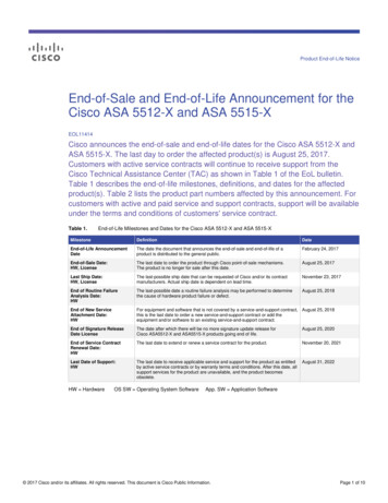
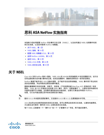
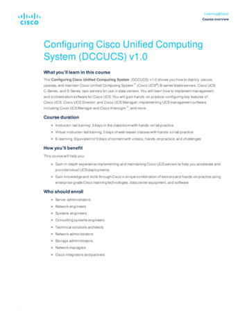
Page 5Initial configurationThe initial configuration of the device is rather straightforward. An easy method for accessing theconfiguration page is by opening a web browser and pointing it to 192.168.1.1. This is the device’sdefault internal address. It will initially ask you for a username and password. There is no username orpassword. Successful authentication will take you to a web page were you have two options. The firstoption is to go on the Cisco ASDM as a local application. This option downloads the ASDM Software andinstalls it, allowing you to access it from the desktop and also manage multiple Security Appliances. Thesecond option is to run the ASDM as a java applet. The startup wizard can be run from this page or byentering the ASDM itself.Startup WizardThe startup wizard consists of thirteen steps:Step 1Asks if you would like to modify an existing configuration or if you would like to reset theconfiguration to factory defaults.Step 2Asks you to enter the ASA host name as well as domain name; it allows you to enable aprivileged mode password which is then required to administer the device using the ASDM orcommand line interface. For this example, the host name is ‘ciscoasa’ and the domain name is‘house.local’.Step 3Allows an auto update server to be enabled. This is disabled for the following examples.Step 4Configures the Internet, or ‘Outside’, VLAN configuration. It offers the choice of which VLAN willbe used to connect to the Internet, allows you to name the interface, set the security level(which should be zero), and allows you to specify how to obtain an IP address. These examplesuse DHCP to obtain an IP address, but for ease of explanation, the IP will be 71.57.38.231 or68.60.231.174 (depending on the image).
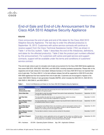
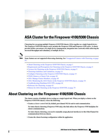
Page 6Figure 1 – Step 4 of the Startup WizardStep 5Allows you to configure the same options as in Step 4, though this time they are for thebusiness, or ‘Inside’, VLAN. These examples use an internal IP range of 192.168.1.0 and a subnetmask of 255.255.255.0. The device has an inside IP address of 192.168.1.1. The security levelfor this interface is 100.Step 6Allows you to configure same options as steps four and five. However, this time they are for ahome, or ‘DMZ’, VLAN configuration. The DMZ in the following examples will be 192.168.10.0with a subnet mask of 255.255.255.0 with the device having an IP address of a 192.168.10.1.The security level for this interface is 50.Step 7Allows you to configure switch port allocation. This lets you choose which ports are allocated towhat VLAN.
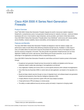
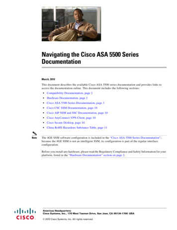
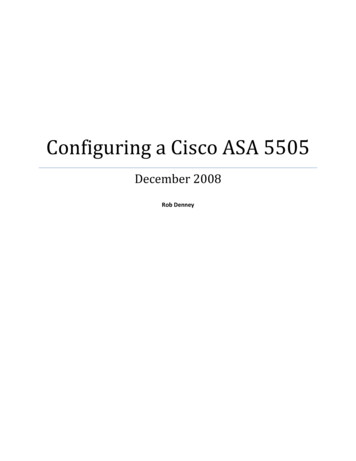
Page 7Figure 2 – Step 7 of the Startup WizardStep 8Gives you two options. First option is to enable traffic between two or more interfaces with thesame security level:By default, interfaces on the same security level cannot communicate with each other.Allowing communication between same security interfaces provides the followingbenefits: You can configure more than 101 communicating interfaces.If you use different levels for each interface and do not assign any interfaces tothe same security level, you can configure only one interface per level(0 to 100). You want traffic to flow freely between all same security interfaces withoutaccess lists. (3)The second option is to enable traffic between two or more hosts connected to the sameinterface. This enables traffic to enter and exit the same interface (4). As mentioned earlier, thebase license forces traffic to be restricted from one VLAN to another VLAN. For initialconfiguration, just make sure that you do not restrict traffic from the inside VLAN to the outsideVLAN. Different configurations of this option will be discussed in the DMZ section.Step 9Allows you to edit the static route table.Step 10Allows you to enable and configure a DHCP server for the inside network. This device wasconfigured to be a DHCP server with an address pool starting at 192.168.1.2 and ending at192.168.1.30.
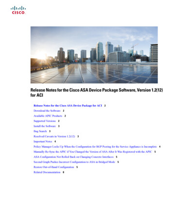
Page 8Figure 3 – Step 10 of the Startup WizardStep 11Allows you to begin configuration of address translation using network address translation(NAT) or port address translation (PAT). There is also an option to disable address translation. Ifan internal client wishes to access the internet when using network address translation, itsinternal address is mapped to an external address owned by the organization. The range ofvalid IP addresses is designated at this step. However, if you do not own a range of IP addressesyou will want to use port address translation. This functions similar to as network addresstranslation. Instead of mapping an internal client’s address to an external address selected froma pool, the device will map the connection to a specific port using the IP address on the outsideinterface.Step 12Configures administrative access to the device. It should be noted that if you disable the HTTPserver, you will not be able to access the device using HTTPS or the ASDM.Step 13Used for Easy VPN remote configuration.Once you’ve finished running the startup wizard, the commands will be sent to the device. If at a laterpoint you wish to change the device access configuration, you may do so by going to the Configurationpanel, followed by Properties, Device Access, and lastly HTTPS/ASDM.
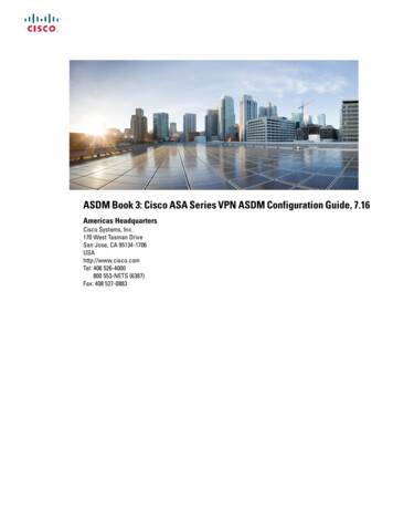
Page 9Figure 4 - HTTPS/ASDM Device AccessDevice Access is also at the point which you are able to limit the access type (SSH, Telnet, ASDM, HTTP,AAA) and also limit what IP addresses or IP address ranges are allowed to access the device.Setting up VLANs and PortsThe initial configuration of the device gives the user two VLANs, inside and outside. The base license, asis being used in these examples, allows for a third VLAN to be configured. This VLAN will be labeled asthe ‘DMZ’. To add a VLAN, go to the Configuration panel and then Interfaces and click ‘Add’. Thefollowing display will appear:Figure 5 – Adding an Interface and selecting Switch ports
P a g e 10From here, you can enable/disable the interface, name it, set the security level, set the IP address of thedevice on the interface, and also select which physical ports will be implemented on this interface. The‘Advanced’ tab allows you to set the MTU, MAC address, as well as where to block traffic from. Thebase license requires one of the three VLANs to block traffic from another zone. The example DMZ usesEthernet0/1, while the Outside uses Ethernet0/0, and the Inside has Ethernet0/2 through Ethernet 0/7.Going to the ‘Switch Ports’ tab gives the user a different view of the ports as well as the ability to editfurther settings. These settings include changing the port to Trunk access mode (not allowed with thebase license), changing the duplex, changing the speed, and lastly the isolation mode (restricting trafficfrom being forwarded from one isolated port to another on the same VLAN). The icons next toEthernet0/6 and Ethernet 0/7 signify that those ports support PoE (Power over Ethernet).Figure 7 – Interface Switch Ports OverviewSecurity levelsSecurity levels are an important concept of Cisco devices. These levels range from 0-100 (0 being thelowest, 100 being the highest). An easy way of thinking about security levels of an interface is to thinkof it as a percentage of trust. An inside network may be trusted all of the time. It will be given a securitylevel of 100. A DMZ, on the other hand, should not be trusted all of the time as it can be vulnerable tothe outside network. We can give this interface a security level of 50. The outside network shouldnever be trusted. It will be given a security level of 0. By default, traffic is allowed to flow from a trustedsource to a less trusted source but the inverse is not true.
P a g e 11Access PoliciesThe access control lists define what type of traffic or who can enter or exit through the device. An accesspolicy serves a similar function to a firewall rule, and each interface has its own lists for incoming andoutgoing traffic.Figure 8 – Access Rules OverviewFigure 8 shows the ASDM view of the Access Rules. These access rules can be viewed and modified inthe Access Rules tab of Security Policy under the Configuration. Each interface has its own implicit rulesfor both incoming and outgoing traffic. The incoming rules deny all traffic of any type to anydestination. The outgoing default rule also denies all traffic. These default rules are only implementedshould an additional rule for that interface be added. For example, if you do not configure a rule foroutgoing connections on the Inside network all traffic is allowed. However, if you add a rule that allowsHTTP traffic to exit the network, only HTTP traffic will be allowed outside unless more rules areconfigured. As a result, it should be noted that outgoing connection rules will not be listed unless a rulein addition to the default rule is added.How to Add PoliciesThe addition and modification of access rules is easy via the ASDM. Choose ‘Add’ then ‘Access Rule’.The following screen will appear:
P a g e 12Figure 9 – Adding an Access RuleFrom this screen, you choose the interface that you wish the rule to apply. Next, choose the direction oftraffic that the rule applies to (incoming or outgoing) and an action (Permit or Deny). The source anddestination can be “any”, “IP address” (including netmask), an interface IP, or a defined network object.You can also choose the protocol (IP, TCP, UDP) and specific service. The services can be chosen from apredefined list or by typing in the ports. Further options include logging, the time range desired for therule to be active, and/or a description.Example Inside PoliciesTo perform even the most simple of operations on the internet (web page browsing) on the Insidenetwork, two rules must be configured: the first rule must allow DNS queries. The second must allowHTTP (a third rule would be required for HTTPS).Figure 10 – Add Access Rule for DNS to InsideFigure 11 – Add Access Rule for HTTP to Inside
P a g e 13Example DMZ PoliciesFor a home or small business DMZ, not much should need to be permitted. It largely depends on therunning servers. For example, if a web server is running, HTTP/HTTPS should be enabled. The sameshould happen for any e-mail related services (i.e. SMTP).The following is an example of an access rule allowing HTTP access to the web server in the DMZ. Itallows any source to send TCP traffic from any port to port 80 (HTTP) of 192.168.10.2 in the DMZ.Figure 12 – Add Access Rule for HTTP to DMZExample Outside PoliciesThe Outside interface will require the same access rules as the DMZ for services that you want to bepublically accessible.NAT PoliciesNetwork Address/Port Address Translation (NAT/PAT) is extremely important for any user who does notdirectly connect his/her computer to a modem. NAT is used to allow many other computers behind therouting device access the internet using the external address without giving away the identity of thehost. This is done by modifying the source and destination information of packets and maintaining a listof connections.How to Add NAT PoliciesNAT Policies can be added, edited, or removed from the Configuration - NAT panel. Select ‘Add’ andchoose the type of policy you want to add. There are multiple options: Static NAT Rule, Dynamic NATRule, NAT Exempt Rule, Identity NAT Rule, Static Policy NAT Rule, and Dynamic Policy NAT Rule. Staticrules map a private address to an external address one-to-one. Dynamic rules map a single address to apool of addresses.
P a g e 14Figure 13 – Editing a Static NAT RuleDemilitarized Zone (DMZ)“DMZ (Demilitarized Zone) is a physical or logical subnetwork that contains and exposes anorganization's external services to a larger, untrusted network, usually the Internet. A DMZ adds anadditional layer of security to an organization's Local Area Network (LAN). An external attacker can onlyaccess equipment that is in the DMZ, rather than the whole of the network” (5). There are twocommonly used structures for a DMZ. The first (shown in Figure 14) is using a single firewall. Thefirewall sits between the external router and the internal network. It separates the DMZ from the restof the LAN. The other structure uses two firewalls. The first firewall filters all traffic only permitting thetraffic which is allowed for the internal and DMZ networks. The other firewall filters traffic to only allowtraffic that originates from the DMZ. This is a more secure method of deploying a DMZ (6). However, forease of creation, we will use the first method.Figure 14 – Example DMZ Configuration (7)There are three requirements when configuring the ASA for a DMZ deployment (8):Internal clients need to be able to communicate with devices on the internet.Internal clients need to be able to communicate with the DMZ web server.External clients need to be able to communicate with the DMZ web server.
P a g e 15The base license of the Cisco device does not allow all of the VLANs to communicate with each other.This can present a problem when attempting to configure a DMZ as it must be on its own VLAN. Thereare only two methods possible when using this device. These are: DMZ- Inside traffic is restricted andOutside- Inside traffic is restricted.DMZ- Inside RestrictedMy initial attempt to create a workable DMZ with the restrictions involved restricting traffic from theDMZ VLAN to the Inside VLAN. This restriction must be set in the Interfaces panel. Once this has beendone and the traffic flow restricted, the next step was to create the necessary NAT policies:Traffic coming from the internet to the external address port 80 is translated to the web serverin the DMZ on port 80.Traffic coming from the DMZ VLAN to port 80 is translated to the web server in the DMZ on port80.Traffic coming from the Inside VLAN to port 80 is translated to the external address port 80.Traffic coming from the internet to the external address port 21 is translated to the FTP server inthe DMZ on port 21.Traffic coming from the DMZ VLAN to port 21 is translated to the FTP server in the DMZ on port21.Traffic coming from the Inside VLAN to port 21 is translated to the external address port 21.In addition to the preceding rules, rules to access the internal routers from the outside were also to beprogrammed:Traffic coming from the internet to the external address over port 800 is translated to aninternal address of 192.168.1.2 on port 80.Traffic coming from the DMZ to the external address over port 800 is translated to an internaladdress of 192.168.1.2 on port 80.Traffic coming from the Inside VLAN to the external address over port 800 is translated to aninternal address of 192.168.1.2 on port 80.These rules were more so to prove that the internal network can still be accessed, given the properinstructions. However, these rules should not be implemented in a production environment; theycreate an unnecessary risk to the network.At the start, this setup appeared to work with the exception of the DMZ being unable to initiatecommunication to the Inside VLAN.I attempted to verify that this setup worked at a later point and found that it was not performing as itwas earlier. This was more of an error on my part, not realizing that the web browser I was using wassimply caching the appropriate web pages and redisplaying them without trying to pull new information.
P a g e 16SummaryThe first attempt at creating a workable DMZ did not work as intended. While clients on the internetwere able to access the content of the web server as well as the FTP server, clients on the Ins
This paper will be focusing on the Cisco ASA 5505 series adaptive security appliance (with base license) and its incorporation into a small business or Home Network. Specifically, it will look at the initial . and load