Transcription
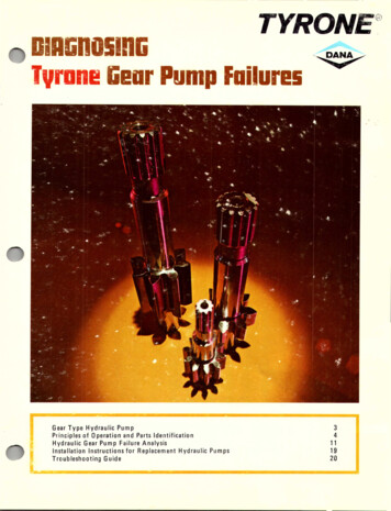
TYRONE IA&n05In&vrane liear Pump FailuresGear Type Hydraulic PumpPrinciples of Operation and Parts IdentificationHydraulic Gear Pump Failure AnalysisInstallationInstructionsfor 920
GlOSSARY OF TERmsWear causedby abrasiveaction of dirt and fine contaminants in the oil.Presenceof air bubbles in hydraulic oil . givesoil a foamy appearance.CAVITATIONFormation and collapse of vapor bubbles in hydraulic oil.Very small particles of abrasive material suspended in hydraulic oil.Usually not visible to the naked eye.2EROSIONRemoval of metal particles from the surface of a part, leaving a rough,pitted area.FLUSHINGThorough cleaning of entire system to remove all contaminants that can orhavecausedpump failures.GEAR TRACKArea in pump housing milled by gear teeth on initial pump break in (atfactory) to provide proper tip clearance.HIGH OILTEMPERATURETemperature above 2000 F, when the oil film weakensand its lubricatingability is reduced.ISOLATION PLATESupport for pressure balance sealsused to separate low pressureand highpressureareasof pressurebalance system.LACK OF OILLow oil level in tank. This can allow suction to be uncovered due tosloshing of oil.METALCONTAMINANTSSmall particles of metal in the hydraulic oil. Probably have worn fromcomponents in the system and mayor may not be visible to the eye.OVERPRESSUREPressurein the system exceedsthe specified relief valve pressure.PRESSUREBALANCEHydraulic loading of pressureplates to keep them firmly againstgear ends.This is essentialfor high pump efficiency.PRESSUREPLATESPlates on each side of gears. The pressure plates and housing form thepumping chamber.TRAPRecessin the pressureplatesthat allow the trapped fluid between the teethof the pump gearsto escape.
IiEAR-TYPEHYDRAULIEpumpsModern machines used in construction, logging, mining andmaterial handling rely to an increasing extent on hydraulicsystems. The increased productivity of these machines requires that hydraulic pumps have large capacities and highpressure ratings to handle the heavier loads, faster cycles,and higher travel speeds. High pressures impose greater stress on all components in thehydraulic system. At the same time, increased reliability isrequired for operational safety. Careful maintenance isessential to reduce failure rate, extend service life, and insuresafe machine operation.Gear-type hydraulic pumps will normally give good performance over a long period of time when operating in aproperly maintained system. Clean oil of the correct grade,regular filter changes, and frequent inspections of allhydraulic system components are essential to hydraulicpump performance . 3
PrinEiple of Tyrone Gl!ar Pump Opl!ratian and Idl!ntifilatianaf PartsA thorough knowledge of design, principle of operation, and function of each partwill help to:1. Diagnose the cause of the failure.2. Determine reuse or replacement of parts.3. Install the pump correctly.Tyrone Hydraulil Pump Typl! and madl!l IdentifilatianFigure 1. Single section Tyrone Mobil-Master Gear Pump.Hydraulic pumps are illustrated and identified inFigures 1 and 2.The correct identification of the type and modelof pump is very important. The information thatfollows covers the Tyrone Mobil-Master Gear Pumpsonly.These gear-type pumps are positive displacementpumps and come in two versions: Reversible andUni-Directional.A reversible pump can operate in either directionof rotation, without any internal changes. The inlet4Figure 2. Double section Tyrone Mobil-Master Gear Pump.and outlet ports are determined by the direction ofrotation.A uni-directional pump operates in one directiononly. It can be assembled for clockwise or counterclockwise operation. However, once it is assembledfor a specific rotation, it can be operated in that direction only. Correct identification of the type ofpump on hand is most important before any servicework is attempted on any hydraulic pump.The following information identifies the individualpump parts, and describes their function.
Parts IdentifiEatianFigure 3. Parts of the single sectiongear pump of the Uni-directional design:l-Retainer.2-Sealing Strip.3-8ack-Up Ring. 4-lsolation ·0-Ring.10-Support Ring. ll-Pressu re Plate.8109211354Figure 4. Parts of the single sectiongear pump of reversible design:1-0- Ring. 2-Flange. 3-ldler Gear.4-Housing. 5-Drive Gear. 6-lsolationPlate. 7-Support Ring. 8-Retainer.g-PressurePlate.10·0·Ring.11-8ack-Up Ring.678910115
Parts IdantifiEatian·(Eant.,3245Figure5. Partsof the double sectiongear pump. All parts shown.but notlisted with a number.are identicaltothose of the single-sectionpump.1-Flange.2-Front dler. 6-Front Idler. 7-Rear Drive.8-Front Drive Gear. 9-Coupling.10-Stud (8 each). O-Rings (notshown) are located on the back ofthe flange. and on both sidesof thecenterbearingplate.687910Figure 6 shows a pressure plate from the uni-directional pump. This plate seals the ends of the gearsto prevent leakage of the fluid from high pressure toinlet. The plate is hydraulically loaded against the endof the gears by discharge pressure. The recess in theplate marked "A" is the trap. This allows fluidtrapped between the teeth to escape at the ends. ThiS.trap is very important in controlling the noise andperformance of the pump. It is on the discharge sideof the pump. The groove marked "8" is a lubrication6
Figure 6.ABgroove. A small portion of the fluid is directed intoeach bore and then down to each bearing, lubricatingthe shafts. The chamfer marked "C" carries high pressure fluid to the proper point on the plate and provides proper balance. The small lines identified by theletter "0" are caused by the gear tips sweeping acrossthe plates. Some discoloration and very slight groovesare quite common in this area.The suction side of the pump housing is shown inFigure 7. During initial break-in at the factory, thegears cu t into the housi ng. The nom inal depth of th iscut is .008" (0,203 mm) and should not exceed .015"(0,381 mm). This gear track provides low gear tipclearance and high volumetric efficiency. Note thesmooth machined appearance of the gear track. Smallbits of metal are sometimes pulled out of this surfaceduring break-in. This is not detrimental.CDFigure 7.GEAR TRACK7
Figure 8.Figure 9.Figure 10.8The drive and idler gears from a properly operatingpump are shown in Figure 8. Note the polishing ofthe loaded side of the gear teeth. Some pitting nearthe root of the tooth will occur after extended operation. The high gloss of the journals also indicates aproperly operating pump.Figure 9 shows the distribution of high pressureand low pressure fluid within the gear cavity.In Figure 10, a section is taken through the centerof the gears. High pressure fluid from the discharge isdirected behind the plates to push them against theends of the gears. The fluid indicated by yellow is lowpressure fluid returning from the ends of the bearingback through drilled passageways to the inlet of thepump.Figure 11 is a cross sectional drawing showing thefluid flow within the single section pump. A portionof the oil being pumped flows down the lubricationgroove in the pressure plates and enters each bearing.This flow is collected at the ends of the bearings andreturns through drilled passageways to the inlet of thepump.Figure 12 shows a cross section of a two sectionFigure 11. Single section pump.
pump along with the path of the fluid within the unitas indicated by arrows. As in the single section pump,part of the discharge flow enters the lubricationgroove in the pressure plate on each end of the gearsand is fed to each bearing. The oil is again collected atthe ends of the bearing and returned back to the inletend through a series of drilled passages.The isolation plates used in reversible gear pumpsare shown in Figure 13. Two of these plates are needed in the bottom of the housing, and two in the top.The isolationplates hold the seal componentsinplace. The plates with a round edge along the outerradius on one edge go in the bottom of the housing.Plates with square edges on the radius go next to thetop flange.Figure 13. IsolationPlates for ReversiblePumps.Figure 14.Pressure distributionon the back side of the pressure plate for a reversible unit when operating clockwise is illustrated in Figure 14.Pressure distributionfor counterclockwiserotationis illustrated in Figure 15.Only two isolation plates are needed per unit inuni-directionalgear pumps.The plate with therounded edges along the outer radius goes in the bot-Figure 12. Two Section Pump.Figure 15.9
Figure 16. IsolationPlates for Uni- Directional PumpsFigure 18. Reversible Uni-Directional Flanges.tom of the housing, with the round edge down. Theplate with square edges along the radius goes on top,next to the flange.In Figure 17, the distribution of the high pressureon the back side of the pressure plates is shown. Thisarea is of sufficient size to keep the pressure platetight against the ends of the gears.A pum p can also be identified as a reversible oruni-directionalunit by the following items: Flange,pressure plate, and isolation plates.Figure 18 shows the flanges for uni-directional andreversible pu m ps. The un i-directional flange is on theright. Note the two threaded holes near the bearingbores. A pipe plug is installed in the hole which is onthe high pressure side of the pump. The location ofthe plug is therefore determined by the direction ofrotation for which the pump is assembled. The flangeon the left side has a check valve on each side, andwill operate automatically for either rotation of thepump.The uni-directional pump pressure plate is on theright and has only one set of traps. (See Figure 19).The reversible pump pressure plate on the left sidehas two sets of traps and a flat on each end of theplate.When changing operating directions of uni-directional pumps, see your Service Manual for details orTyrone Pump Bulletin No.1 01.10Figure 19. Reversible Uni-Drectional Pressure Plates.
HYDRAULI[ IiEAR pumpFAILUREAnALYSIS Dlterminl[ausl af FailurlSome failures result from only one cause and thereason is often obvious. Other failures are a result of acombination of causes. You must be very careful todetermine all of the causes and elim inate them toprevent repeat failure. Examine all of the componentsavailable, and consider all other factors which mayhave contributed to the cause. It is often very helpfulto have some history of the machine. To completelyanalyze a hydraulic pump failure consider the following items:1.2.3. 4.5.6.Condition of each pump component.Type and condition of hydraulic oil and filters.Operating conditions and symptoms beforefailure.Conditions of other hydraulic system components.Severity of job application.Amount of service received from pump before failure.7.Previous failures and repairs in the hydraulicsystem.PrluentRlplat FailurlsA knowledge of the pump service life is an essentialpart of pump servicing. Even if the pump provided asatisfactory period of service before failure, severalprecautions must be taken to insure that the newpump will provide a similar period of service. SeeInstallation Instructions for Replacement HydraulicPumps, Page 19. If the machine's records indicatethat pump life shortens with each replacement pump,you can be sure that these instructions were not followed. The troubleshooting information and the illustrations should help in diagnosing hydraulic pumpfailures .For details on operation, service, and repair of anypart of the hydraulic system refer to the appropriateservice manual for the machine.11
WHAT [RUSESHYDRAULII pumpFAILURE?There are several causes for gear pump failure. Thisbooklet discusses these causes and the various indicators or symptoms of each cause. It further explainspump failure analysis and the preventive measuresyou can take to avoid repeat failure. Common causesof pump failure are:1.2.3.4.5.6.7.8.9.Abrasive wear caused by fine particles.Abrasive wear caused by nietal particle ;Incorrect installation.Aeration or cavitation.Lack of oilDamage caused by meta.l objects.Excessive heat.Overpressure.Incorrect assembly.ABRASIUE WEAR EAUSED BYFinE PARTIElESAbrasive wear caused by fine particles is the mostcommon cause of pump failure. Its symptom is usually a gradual decrease in power and speed of thehydraulic system. Fine particles (dirt, and other foreign matter) circulating through the system causewear on all components,especially noticeable onpressure plates, housing bores, and in the shaft bearing area.Dirt can enter the system through worn seals, or ifthe system is serviced in dusty conditions, or withdirty equipment. Always wipe tank caps, funnels, andall areas around the filler neck clean before openingthe tank. Immediately cover all disconnected lines,fittings and openings. Check the rod wiper seals to besure they are operating effectively.The effectiveness of the cylinder rod wiper sealscan be checked as follows, depending on the design ofthe seal:A. V- Type Rod Packings:1. Extend the cylinder rod (WARNING: Whenchecking lift cylinder wipers, block thebucket securely in raised position.)122.Remove the bolts securing the wiper seal retainer to the cylinder head.3. Coat the rod with grease.4. Slide the retainer and wiper seal up the rod.5. Examine the rod. The wiper should wipe therod clean. If the wiper does not remove allthe grease 3600 around the rod, it is tooloose and should not be used.B. Lip-Type Wiper Seals with Buffer and U-Cup RodSeals.These rod seal arrangements do not have a retaineron the cylinder head that can be removed for checking the wiper seal. The wiper seal is mounted insidethe counterboreof the head and can be inspectedvisually. A better check can be made by trying toinsert a .001" or .002" (0,025 mm or 0,050 mm)feeler gauge between the wiper seal lip and the rod. Ifthe wiper seal is effecti
The information that follows covers the Tyrone Mobil-Master Gear Pumps only. These gear-type pumps are positive displacement pumps and come in two versions: Reversible and Uni-Directional. A reversible pump can operate in either direction of rotation, without any internal changes.

