Transcription
AVS Anchor -LLumbar Cage SystemSurgical Technique
AVS Anchor-L Lumbar Cage SystemSurgical TechniqueTable of ContentsIntroduction . . . . . . . . . . . . . . . . . . . . . . . . . . . . . . . . . . . . . . . . . . . . . . . . . . . . . . . . . 3Preoperative Planning . . . . . . . . . . . . . . . . . . . . . . . . . . . . . . . . . . . . . . . . . . . . . . . . . 4Approach – Transperitoneal or Retroperitoneal . . . . . . . . . . . . . . . . . . . . . . . . . . . 4Cage Height Determination . . . . . . . . . . . . . . . . . . . . . . . . . . . . . . . . . . . . . . . . . . . . 4Step 1: Exposure . . . . . . . . . . . . . . . . . . . . . . . . . . . . . . . . . . . . . . . . . . . . . . . . . . . . . . 4Step 2: Perform the Annulotomy & Discectomy . . . . . . . . . . . . . . . . . . . . . . . . . . . 5Step 3: Prepare the Endplates . . . . . . . . . . . . . . . . . . . . . . . . . . . . . . . . . . . . . . . . . . . 6Step 4: Determine Cage Size . . . . . . . . . . . . . . . . . . . . . . . . . . . . . . . . . . . . . . . . . . . . 6Step 5: Load the Cage . . . . . . . . . . . . . . . . . . . . . . . . . . . . . . . . . . . . . . . . . . . . . . . . 10Step 6: Insert the Cage . . . . . . . . . . . . . . . . . . . . . . . . . . . . . . . . . . . . . . . . . . . . . . . . 13Step 7: Prepare the Screw Pathway. . . . . . . . . . . . . . . . . . . . . . . . . . . . . . . . . . . . . . 14Step 8: Insert the Screws . . . . . . . . . . . . . . . . . . . . . . . . . . . . . . . . . . . . . . . . . . . . . . 15Step 9: Remove the AIOG . . . . . . . . . . . . . . . . . . . . . . . . . . . . . . . . . . . . . . . . . . . . . 16Step 10: Insert the Locking Plate . . . . . . . . . . . . . . . . . . . . . . . . . . . . . . . . . . . . . . . 17Implant Removal . . . . . . . . . . . . . . . . . . . . . . . . . . . . . . . . . . . . . . . . . . . . . . . . . . . . 18Standard Instruments . . . . . . . . . . . . . . . . . . . . . . . . . . . . . . . . . . . . . . . . . . . . . . . . 19Standard Implants . . . . . . . . . . . . . . . . . . . . . . . . . . . . . . . . . . . . . . . . . . . . . . . . . . . 22Auxiliary Instruments. . . . . . . . . . . . . . . . . . . . . . . . . . . . . . . . . . . . . . . . . . . . . . . . 23Auxiliary Implants. . . . . . . . . . . . . . . . . . . . . . . . . . . . . . . . . . . . . . . . . . . . . . . . . . . 25Indications for Use . . . . . . . . . . . . . . . . . . . . . . . . . . . . . . . . . . . . . . . . . . . . . . . . . . . 27Contraindications, Cautions and Pre-Operative Cautions . . . . . . . . . . . . . . . . . . 27AcknowledgmentsStryker Spine wishes to thank the following surgeons for their dedication andcontributions to the development of the AVS Anchor-L Lumbar Cage System.Glenn Amundson, MDAlexander Bailey, MDDouglas Beard, MDAlexandre De Moura, MDJohn Gorup, MDRobert Josey, MDDan Lee, MD2
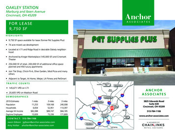
AVS Anchor-L Lumbar Cage SystemSurgical TechniqueIntroductionThe Stryker Spine AVS Anchor-L Lumbar Cage System includes a PEEK cage, threetitanium bone screws, and a titanium locking plate that will be used together asan interbody fusion device for the lumbosacral spine (L2-S1). The PEEK cageincorporates three tantalum markers that aid in radiographic visualization. Thesemarkers are positioned on the posterior end and lateral aspects of the cage. Themarkers span the total height of the cage in order to show the overall height relativeto the vertebral endplates as well as the cage-to-endplate proximity. The upper andlower aspects of the lumbar cage are open, and the superior and inferior surfaces haveserrations that assist in positive anchorage and seating. The AVS Anchor-L PEEKcage and titanium bone screws are available in a variety of sizes in order to allow thesurgeon to choose those that are best suited to the patient’s anatomy and pathology.The AVS Anchor-L device is designed to be inserted via a transperitoneal orretroperitoneal surgical approach to the lumbosacral spine. After the cage isimplanted, the bone screws should be inserted, and then the construct is locked witha titanium locking plate once it is determined that the construct is in its desired finalposition.The AVS Anchor-L Lumbar Cage System may be used as an intervertebral devicewith integrated fixation or in conjunction with supplemental fixation. When usedas a intervertebral device with integrated fixation, the AVS Anchor-L PEEK Cagemust be used with three internal screws and plate fixation provided by AVS Anchor-LFixation Screws and Locking Plate. If AVS Anchor-L is used with less than three ornone of the provided screws, additional supplemental fixation that has been clearedby the FDA for use in the lumbosacral spine must be used to augment stability. Theaccompanying Locking Plate must be used anytime the device is used with anynumber of screws.3
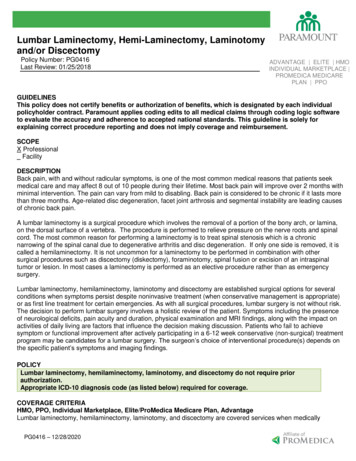
AVS Anchor-L Lumbar Cage SystemSurgical TechniquePreparationApproach - Transperitoneal or RetroperitonealDetermine surgical approach (transperitoneal or retroperitoneal). Surgeonpreference, patient anatomy, and patient pathology should determine the approachused.The Reliance AL Instruments can be used in either a transperitoneal orretroperitoneal approach to the lumbosacral spine and may depend on which level ofthe spine is being treated. Anterior access is required for the insertion of the screwsand locking plate. This technique details a retroperitoneal approach.Cage Height DeterminationAnalyze preoperative imaging to determine height of the cage. The cage must befirmly seated with a secure fit in the disc space when the segment is distracted.Step 1: ExposureExpose the midline of the intervertebral disc. Take care to expose the segment withsufficient space on either side of the midline to allow for placement of the device(widths range from 30mm – 40mm) (Fig. 1).Figure 1Consideration: Mark the midlineof the disc/vertebral body underfluoroscopic guidance. This markwill assist in determining theannulotomy site width (Fig. 2).4Figure 2
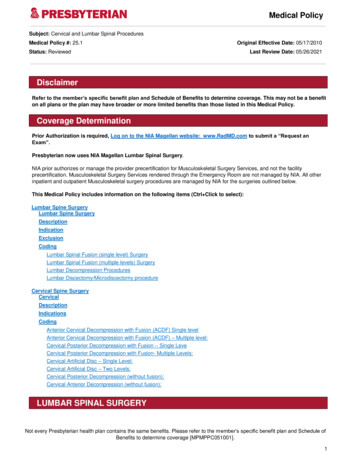
AVS Anchor-L Lumbar Cage SystemSurgical TechniqueStep 2: Perform the Annulotomy &DiscectomyUsing the Long Handle Knife (Reliance AL 48361277) cut a window in the annulus.It is important that the window is centered on the vertebral midline in order toprepare the position for the implant (Fig. 3).Figure 3. Long Handle KnifeFigure 3. Long Handle Knife48361277Warning: Care is required while performing the annulotomy with the LongHandle Knife as the blade can result in serious damage to the vascular elements.Blades for the Long Handle Knife are not included with the Reliance AL System.A cobb can be used to separate the cartilaginous endplate from the bony vertebralendplate (Fig. 4).Figure 4. CobbUse a pituitary rongeur to remove disc material. To accommodate a range of needs,pituitary rongeurs are available in sizes of 4mm and 8mm, and in three differentorientations; up, down, and straight. The pituitary rongeurs can also be used toremove disc material and cartilaginous tissue from the superior and inferior vertebralendplates.A paddle distractor or a lordosed paddle distractor may be used to distract and allowroom to work on the contralateral side.Curettes can also be used to remove disc material and cartilage from the superiorand inferior vertebral endplates. Curettes are offered in straight, up and upward bendorientations.Note: The Reliance AL Lumbar Fusion System includes instruments usedduring annulotomy, discectomy, bone removal, and endplate preparation. Theseinstruments include cobbs, pituitary rongeurs, kerrisons, paddle distractors,curettes, and rasps. (See Reliance AL Surgical Technique for informationregarding these instruments.)Once the discectomy has been performed, the Posterior Longitudinal Ligament(PLL) Stripper may be used. The instrument may be used to release the PLL fromthe posterior edge of both the upper and lower vertebral bodies if deemed necessaryby the surgeon. The value of releasing the PLL is to optimize parallel distraction andto permit maximum opening of the space for neural elements if required. If the PLLStripper is utilized, use caution to protect the neurological structures (Fig. 5).Figure 5. Posterior Longitudinal Ligament(PLL) Stripper48361238Figure 6. Reliance AL Discectomy Distractor48361150Distraction of the discectomy site is important to restore lordosis, open the neuralforamen, and stabilize the implant. The Reliance AL Discectomy Distractor can beused to provide distraction for the discectomy, endplate preparation, implant trialing,and implant insertion. The Modular Straight Tips or Offset Tips are recommended(Fig. 6).5
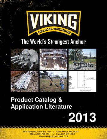
AVS Anchor-L Lumbar Cage SystemSurgical TechniqueStep 3: Prepare the EndplatesAdequate preparation of the endplates is important to enhance vascular supply to thefusion site. The AVS Anchor-L Lumbar Cage System includes Single Side Rasps inup, straight, and down facing orientations. It is recommended to move these rasps inan anterior-posterior motion, and a medial-lateral motion to remove the superficialcartilaginous layers of the endplate and expose bleeding cancellous bone, beingcareful not to remove too much subchondral bone. This helps avoid subsidence andloss of segmental stability (Fig. 7).Figure 7489982006mm Single Side Straight Rasp489983006mm Single Side Angled Rasp Up489984006mm Single Side Angled Rasp DownCaution: In patients with sclerosis of the endplates, more rigorous rasping maybe useful to expose a bleeding surface. Care should be used to not remove thedense cancellous endplate.Consideration: Additional raspsNote: Depth notches indicate depth of rasp at 22mm, 25mm, and 28mm whichcan be found in the Reliance AL set,and may also be used to help preparethe endplates.represent the different trial footprint depth options.Step 4: Determine Cage SizeCage Sizes/Trial SizesAVS Anchor-L Lumbar Cage and Trial Sizes*FootprintsHeightsLordosisFigure 822x30mm25x35mm28x40mm10-20mm (2mm incr.) 10-20mm (2mm incr.) 10-20mm (2mm incr.)4 , 8 , 12 , 16 4 , 8 , 12 , 16 4 , 8 , 12 , 16 Final cage size can be determined using the appropriate Solid Trials. Solid Trialsrange from 10mm-20mm matching the cage options in footprint, height, andlordosis (Fig. 8).* The Standard AVS Anchor-L Lumbar Cage Set includes the following:Footprints:22x30mm and 25x35mmHeights:10-16mmLordosis:4 , 8 , 12 6The 28x40mm footprint, the 18mm and 20mm heights, and the 16 cages are only available inthe AVS Anchor-L Auxiliary Set (Loaners only).
AVS Anchor-L Lumbar Cage SystemSurgical TechniqueThe Trial Handle can be used for trial insertion. The Trial Stop was designed toprevent the trial from being inserted too posteriorly which may inaccurately representthe position of the implant when placed with the All-In-One Guide (AIOG). Oncethe Trial Stop has been placed onto the Trial Handle, attach the trial by threading thedistal end into the hole in the trial. Insert the trial into the disc space to confirm theappropriate size cage. Fluoroscopy can assist in confirming the proper fit (Fig. 9).If the trial appears too small or too tight, the next larger or smaller size, respectively,should be chosen until the firmest fit is obtained. The Solid Trial can be removedfrom the Trial Handle by unthreading the trials from the handle.Figure 9. Trial Handle48361234Note : If using the AVS Anchor-L lumbar cage as an anterior lumbar cage withsupplemental fixation, do not use the Trial Stop during trialing. Without theTrial Stop, the trials can be countersunk into the disc space to give an accuraterepresentation of where the final implant will sit (Fig. 10).Figure 10. Trial Stop48991014Consideration: Lateral imagingis recommended for confirmingposterior trial-to-endplate contact.There should be no gaps between theendplates and the trial (Fig. 11).Consideration: It is importantto not oversize with the trial, as theoverall implant height is 1mm tallerthan the trial when the height ofthe serrations (0.5mm per side) isincluded.Figure 117
AVS Anchor-L Lumbar Cage SystemSurgical TechniqueAnchor-L Height SpecificationsAVS Anchor-L Anterior vs. Posterior Height22mm x 30mm footprint8Posterior Height(Base of Teeth)Nose HeightAnterior Height(Base of /Post[mm]NoseHeight[mm]10mm x 4 108.91.16.810mm x 8 107.82.25.510mm x 12 106.73.34.112mm x 4 1210.91.18.812mm x 8 129.82.27.512mm x 12 128.73.36.112mm x 16 127.64.54.714mm x 4 1412.91.110.814mm x 8 1411.82.29.514mm x 12 1410.73.38.114mm x 16 149.64.56.716mm x 4 1614.91.112.816mm x 8 1613.82.211.516mm x 12 1612.73.310.116mm x 16 1611.64.58.718mm x 4 1816.91.114.818mm x 8 1815.82.213.518mm x 12 1814.73.312.118mm x 16 1813.64.510.720mm x 4 2018.91.116.820mm x 8 2017.82.215.520mm x 12 2016.73.314.120mm x 16 2015.64.512.7
AVS Anchor-L Lumbar Cage SystemSurgical TechniqueAVS Anchor-L Anterior vs. Posterior HeightAVS Anchor-L Anterior vs. Posterior Height25mm x 35mm footprint28mm x 40mm ght[mm]DifferenceAnt/Post[mm]NoseHeight[mm]10mm x 4 108.71.36.610mm x 4 108.51.56.410mm x 8 107.42.65.010mm x 8 106.93.14.610mm x 12 106.04.03.510mm x 12 105.44.62.812mm x 4 1210.71.38.612mm x 4 1210.51.58.412mm x 8 129.42.67.012mm x 8 128.93.16.612mm x 12 128.04.05.512mm x 12 127.44.64.812mm x 16 126.75.33.912mm x 16 125.96.13.014mm x 4 1412.71.310.614mm x 4 1412.51.510.414mm x 8 1411.42.69.014mm x 8 1410.93.18.614mm x 12 1410.04.07.514mm x 12 149.44.66.814mm x 16 148.75.35.914mm x 16 147.96.15.016mm x 4 1614.71.312.616mm x 4 1614.51.512.416mm x 8 1613.42.611.016mm x 8 1612.93.110.616mm x 12 1612.04.09.516mm x 12 1611.44.68.816mm x 16 1610.75.37.916mm x 16 169.96.17.018mm x 4 1816.71.314.618mm x 4 1816.51.514.418mm x 8 1815.42.613.018mm x 8 1814.93.112.618mm x 12 1814.04.011.518mm x 12 1813.44.610.818mm x 16 1812.75.39.918mm x 16 1811.96.19.020mm x 4 2018.71.316.620mm x 4 2018.51.516.420mm x 8 2017.42.615.020mm x 8 2016.93.114.620mm x 12 2016.04.013.520mm x 12 2015.44.612.820mm x 16 2014.75.311.920mm x 16 2013.96.111.09
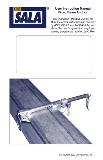
AVS Anchor-L Lumbar Cage SystemSurgical TechniqueAfter trialing, if it is determined that a 10mm, 12mm, or 14mm cage will beimplanted, a Marking Guide can be used to aid surgeons in identifying the areas ofbone from the superior and inferior vertebral bodies that will need to be removedto allow for accurate screw insertion. Attach the appropriate Marking Guide (heightand footprint matching the cage size determined by trialing) to the Trial Handle.Insert the Marking Guide into the disc space. Once the guide has marked the areasof bone needing to be removed, remove the guide (Fig. 12). Referencing the notchescreated by the Marking Guide, use a rongeur to remove any bone that may interferewith screw placement (Fig. 13).Figure 12Figure 12. Marking Guide10x22x30 Marking Guide4899910214x25x35 Marking Guide4899014610x25x35 Marking Guide4899010210x28x40 Marking Guide*4899110212x22x30 Marking Guide4899912612x28x40 Marking Guide*4899112614x22x30 Marking Guide4899914614x28x40 Marking Guide*4899114612x25x35 Marking Guide48990126*Included in the Auxilary Instrument Set only.Note: It will be important to use the Marking Guides in the orientation that thescrews will eventually be inserted.Note: All Marking Guides have 16 of lordosis. The design intent is to avoidposteriorly over distracting a lordotic disc space.Note: It is important to use the appropriate size Marking Guide relative to theimplant height, as using a height that is shorter than the disc space could allowthe guide to advance too far posteriorly.Figure 13Step 5: Load the CageOnce the final cage size has been determined, select the corresponding AVS Anchor-LPEEK cage from the tray. Place the cage into the appropriate footprint on the GraftBlock (Fig. 15), and use the Graft Impactor (Fig. 16) to pack autogenous bone graftinto the open cavities of the cage (Fig. 14).Figure 1410Figure 15. Graft Block48999010Figure 16. Graft Impactor48999020
AVS Anchor-L Lumbar Cage SystemSurgical TechniqueAnchor-L Graft VolumesAVS Anchor-L Graft Volume22mm x 30mm footprintSize4 8 12 16 2.92.82.72.618mm3.33.23.13.020mm3.83.63.53.4Option 1: Interbody TechniqueAfter the cage has been packed with bone graft, attach the cage to the Implant Holderby placing the distal end of the holder onto the front of the cage and then depressingthe lever arm to tighten the arms into the lateral grooves on the cage (Fig. 17).With the leading edge of the cage slightly between the vertebral endplates, gentlyimpact the proximal end of the Implant Holder to safely and gradually insert thecage.Reminder: If any screws are used, the Locking Plate must be inserted. If lessthan three screws are used, supplemental fixation that is cleared for use in thelumbosacral spine must be utilized.AVS Anchor-L Graft Volume25mm x 35mm footprintSize4 8 12 16 4.34.13.93.718mm5.04.74.54.320mm5.65.45.25.0AVS Anchor-L Graft Volume28mm x 40mm footprintSize4 8 12 16 6.25.85.55.118mm7.16.76.46.020mm7.97.67.36.9Figure 17. Implant Holder4899200111
AVS Anchor-L Lumbar Cage SystemSurgical TechniqueOption 2: Stand Alone TechniqueAfter the cage has been packed with bone graft, attach the appropriate height AllIn-One Guide (AIOG) to the cage by aligning the laser marking on the AIOG armwith the corresponding laser marking on the side of the cage (Fig. 18). The AIOG islocked to the cage by using the AIOG Small Locking Driver (Fig. 19) to tighten theAIOG Locking Screw. (Fig. 20)Figure 19. AIOG Small Locking Driver48992115Figure 20. AIOG Locking Screw48992110Figure 18Note: The AIOG’s are cage height specific. There are six AIOG’s. For example, ifa 12mm cage is to be implanted, the 12mm AIOG must be used (Fig. 21).10mm All In One Guide4899201016mm All In One Guide4899201612mm All In One Guide4899201218mm All In One Guide*4899201814mm All In One Guide4899201420mm All In One Guide*48992020*Included in the Auxiliary Instrument Set only.Figure 21Note: Any screwdriver in the set, in addition to the Small Locking Driver, maybe used to tighten or loosen the AIOG Locking Screw at any point during theprocedure, as these screws also have a 3.5mm hex interface.By fully tightening the AIOG Locking Screw, the AIOG is firmly attached to the cage.Be sure that the AIOG is flush with the anterior wall of the implant. Attach the AIOGHolder to the AIOG cage construct by using the quick release feature of the AIOGHolder.Note: The AIOG Locking Screw is a separate piece, and may thread completelyout. This allows for cleaning should tissue become lodged in the threads. If aLocking Screw (Fig. 22) is misplaced, simply use one of the extra Locking Screwsin the set, or a Locking Screw from a different size AIOG.Tip: If the Locking Screw will not advance, back it up one turn, slightly depressthe gold arm of the AIOG, and then advance the Locking Screw. The AIOGLocking Screw should not be over-tightened.Figure 22. AIOG Locking Screw48992110Figure 23. AIOG Holder48992000No
The Stryker Spine AVS Anchor-L Lumbar Cage System includes a PEEK cage, three titanium bone screws, and a titanium locking plate that will be used together as . firmly seated with a secure fit in the disc space when the segment is distracted . Step 1: Exposure Expose the midline of the i