Transcription
CSA Today, Vol. III, No. 12Design of Anchor Reinforcement in Concrete PedestalsWidianto, Chandu Patel, and Jerry OwenWidianto is a structural engineer on the Shell SUEx 1 project. He received his B.S,M.S.E., and Ph.D. from the University of Texas at Austin. He is a member of the ASCETask Committee on Anchor Rod Design, and an associate member of the Joint ACIASCE Committee 445 (Shear and Torsion), ACI Committees 351 (Foundations forEquipment and Machinery) and 440 (Fiber Reinforced Polymer Reinforcement).Chandu Patel earned his Bachelors of Science in Civil Engineering from GujaratUniversity, Ahmedabad, India and Masters in Structural Engineering from OklahomaState University. He has been with Bechtel since 1981. He has over 30 years ofexperience, primarily on Petroleum and Chemical projects and Pre-engineered Buildings.He is a member of the ASCE Task Committee on Anchor Rod Design. Presently, Chanduis the ISBL Lead on the Angola LNG project.Jerry Owen earned his Bachelors of Science in Civil Engineering from Mississippi StateUniversity and has been with Bechtel since 1981. He has over 30 years of experience,primarily on Petroleum and Chemical projects. He is a member of the ASCE TaskCommittee on Anchor Rod Design. Presently, Jerry is the Engineering Group Supervisorfor the CSA team on the Shell SUEx 1 project.ABSTRACTEven though the Appendix D of the ACI 318-05 permits the use of supplementaryreinforcement to restrain concrete breakout, it does not provide specific guidelines indesigning such reinforcement. This paper presents a method for designing anchorreinforcement in concrete pedestals, where un-reinforced concrete is insufficient to resistanchor forces. Anchor reinforcement consists of longitudinal rebar and ties to carryanchor tension forces and shear forces, respectively. The Strut-and-Tie Model isproposed to analyze shear force transfer from anchors to pedestal and to design therequired amount of shear reinforcement. A proposed design procedure is illustrated in anexample problem.KEYWORDS: Anchor, Anchorage, Anchor reinforcement, Strut-and-Tie Model1
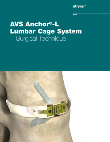
CSA Today, Vol. III, No. 121. INTRODUCTIONThe Appendix D of the ACI 318-05 provides design requirements for anchors in unreinforced concrete. It addresses only the anchor strength and the un-reinforced concretestrength:1. Breakout strength,2. Pullout strength,3. Side-face blowout strength4. Pryout strength.Even though the Appendix D of the ACI 318-05 permits the use of supplementaryreinforcement to restrain the concrete breakout (Section D.4.2.1), it does not providespecific guidelines in designing such reinforcement. Commentary of Section D.4.2.1indicates that the designer has to rely on other test data and design theories in order toinclude the effects of supplementary reinforcement.In petrochemical industry, concrete pedestals commonly support static equipment (i.e.horizontal vessels and heat exchangers) and pipe-rack or compressor building columns.In order to fully-develop the strength of anchor in un-reinforced concrete, the AppendixD of the ACI 318-05 requires the use of significantly large concrete pedestals/octagons. Itis generally not economical to provide such large concrete pedestals/octagons. Therefore,the anchorage design in petrochemical industry almost always includes designingsupplementary reinforcement. When supplementary reinforcement is used to transfer thefull design load from the anchors, it is generally referred as anchor reinforcement. Figure1 shows anchors of a compressor building column on a reinforced concrete pedestal.2
CSA Today, Vol. III, No. 12Figure 1. Pedestal supporting a compressor-building columnThis paper presents a method for designing anchorage in concrete pedestals with anchorreinforcement to anchor static equipment or columns in petrochemical facilities. Theanchor tension and shear forces are assumed to be resisted by the vertical reinforcing barsand ties, respectively. The calculation for determining the required amount of verticalreinforcing bars and ties is presented. A design example of column anchorage in areinforced concrete pedestal is given to illustrate the proposed design method.2. DESIGN PHILOSOPHYThe following general design philosophy is used when the anchor forces are assumed tobe resisted by the steel reinforcement:1. Concrete contribution is neglected in proportioning the steel reinforcement.2. When a non-ductile design is permitted, the reinforcement should be designed toresist the factored design load.3. When a ductile design is required, the reinforcement should be proportioned todevelop the strength of the anchor. If the anchor is sized for more than 2.5 times3
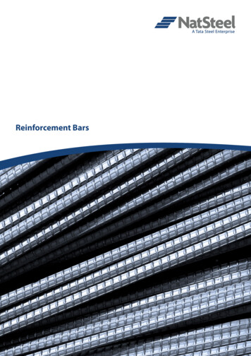
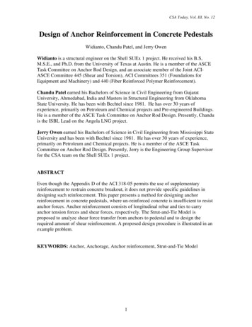
CSA Today, Vol. III, No. 12factored tension design loads, it is permitted to design the reinforcement to carry2.5 times the factored design load, where 2.5 is an overstrength factor.4. When reinforcement is used to restraint concrete breakout, the overall anchoragedesign should ensure that there is sufficient strength corresponding to the threeother failure modes described in the Introduction (pullout failure, side-faceblowout failure, and pryout failure).The three failure modes will be addressed as follows:a. The pullout strength of headed anchors Np can be estimated using the Eq. (D-15) of theACI 318-05 (i.e. N p 8 Abrg f c ' , where Abrg is the net bearing area of the anchor head).b. The side-face blowout failure can be prevented by providing enough edge distance.Section D.5.4 of the ACI 318-05 implicitly indicates that the side-face blowout failureshould be checked when the edge distance c is smaller than 0.4 times the effectiveembedment depth hef (c 0.4 hef). Since hef of anchors in reinforced pedestals is usuallygoverned by the required development length for reinforcing steel (which can besignificantly deeper than the hef,min of 12 times anchor diameter do) and since the side-faceblowout failure is independent of the embedment depth when the embedment depth isdeeper than 12″ (Furche and Elingehausen, 1991), the minimum edge distance of0.4 12do 4.8do can be used to prevent the side-face blowout failure. However, in orderto satisfy the required minimum edge distance for cast-in headed anchors that will betorqued, the minimum edge distance of 6do should be used (Section D.8.2, ACI 318-05).Therefore, for simplicity and to prevent the side-face blowout failure, the minimum edgedistance of 6do is recommended.When it is impossible to provide the minimum edge distance of 6do, the side-faceblowout strength should be calculated using Section D.5.4 of the ACI 318-05. Inaddition, reinforcement may be provided to improve the behavior related to concreteside-face blowout (Fig. 2). Furche and Elingehausen (1991) found that the size of thelateral blow-out at the concrete surface was 6 to 8 times the edge distance. Cannon et al.(1981) recommended spiral reinforcement around the head. It should be emphasized thattransverse reinforcement (ties) did not increase the side-face blowout capacity (DeVrieset al. (1998)). Large amount of transverse reinforcement installed near the anchor headonly increased the magnitude of load that was maintained after the side-face blowoutfailure occurred.4
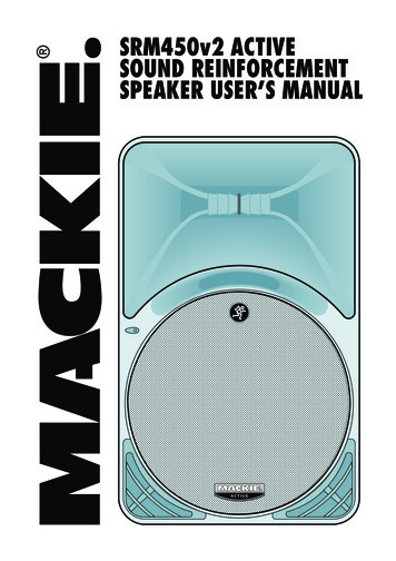
CSA Today, Vol. III, No. 12Shear reinforcementcSpiral reinforcementto restraint concreteside-face blowoutc : edge distance 6c – 8cPotential failuresurfaceFigure 2. Reinforcement around the head to improve the behavior related to concreteside-face blowoutWhen the reinforcement is used to restraint concrete side-face blowout, it should bedesigned to carry the lateral force causing the side-face blowout. Cannon et al. (1981)indicated that for conventional anchor heads, the lateral force causing side-face blowoutmay be conservatively taken as ¼ of the tensile capacity of the anchor steel (based on thePoisson effect in the lateral direction). A more complex procedure to calculate the lateralforce is given in Furche and Elingehausen (1991). In general, the Furche andElingehausen’s procedure gives a smaller lateral load than that recommended by Cannonet al. (1981).c. The pryout failure is only critical for short and stiff anchors. It is reasonable to assumethat for general cast-in place headed anchors with hef,min 12 do, the pryout failure willnot govern.3. DESIGNING STEEL REINFORCEMENT TO CARRY TENSION FORCESThe vertical reinforcement intersects potential crack planes adjacent to the anchor headthus transferring the tension load from the anchor to the reinforcement as long as properdevelopment length is provided to develop the required strength, both above and belowthe intersection between the assumed failure plane and reinforcement (Fig. 3). Thedevelopment length may be reduced when excess reinforcement is provided per section12.2.5 of the ACI 318-05 (but cannot be less than 12″). Reduction in the development5
CSA Today, Vol. III, No. 12length cannot be applied in the areas of moderate or high seismic risk. In order to limitthe embedment length of anchor, a larger number of smaller-size reinforcing bars ispreferred over fewer, larger-size reinforcing bars.To be considered effective, the distance of the reinforcement from the embedded anchorhead or nut should not exceed one-third of the embedment length of the anchor hef, asshown in Fig. 3 (Cannon et al., 1981).dmaxTcoverNote:To be considered effective forresisting anchor tension, themaximum distance from anchorhead to the reinforcement, dmax,shall be not more than hef/3.hef ldPierheight35 Construction jointldhSidecoverdbdmax hef /3Figure 3. Reinforcement for carrying anchor tension forceWhen a non-ductile failure is permitted, the required area of steel reinforcement Ast canbe determined as follows:A st Tuφ f(1)y6
CSA Today, Vol. III, No. 12When a ductile failure is required:Ast Ase f utafy(2)However, the anchor is sized for more than 2.5 times factored tension design loads Tu, itis permitted to design the reinforcement to carry 2.5 times Tu to satisfy IBC 2006 andASCE 7-05 requirements for Seismic Design Categories C and above where ductilitycannot be achieved. The required area of steel reinforcement Ast can be determined asfollows:Ast 2.5 Tuφ fy(3)where:Ase effective cross-sectional area of anchorTu factored tension design load per anchorφ 0.90, strength reduction factor (Chapter 9 of the ACI 318-05)fy specified minimum yield strength of reinforcementfuta specified minimum tensile strength of anchor steelDesign for anchor ductility requires that the necessary conditions for elongation over areasonable gage length are fulfilled (i.e., that strain localization will not limit the yieldstrain). This may involve the use of upset threads or other detailing methods to avoidstrain localization.4. DESIGNING STEEL REINFORCEMENT TO CARRY SHEAR FORCESWhere allowed by Code, shear may be transferred by friction between the base plate andthe concrete with the anchors are used for transferring tension force only. For large shearforces, where the shear friction is insufficient, shear lugs or anchors can be used totransfer the load. The shear forces must be transferred to concrete pedestal. Strut-and-tiemodels can be used to analyze shear transfer to concrete pedestal.4.1. What is the strut-and-tie models (STM)?A strut-and-tie model (STM) is an ultimate strength design method based on theformation of a hypothetical truss that transmits forces from loading points to supports.The STM utilizes concrete struts to resist compression and reinforcing ties to carrytension. Design using STM involves calculating the required amount of reinforcement toserve as the tension ties and then checking that the compressive struts and nodal zone(joints) are sufficiently large enough to support the forces. A key advantage of designusing STM is that the designer can visualize the flow of stresses in the member. A7
CSA Today, Vol. III, No. 12common application of the STM is to design “disturbed” regions (i.e. at concentratedloads and reactions, and at geometric discontinuity), where the flow of stresses cannot bepredicted by normal “beam theory” (i.e. linear strain distribution).The most important assumptions in the STM are:1. Failure is due to the formation of a mechanism resulting from yielding of oneor more ties.2. Crushing of the concrete struts should not occur prior to yielding of the ties.This is prevented by limiting the stress levels in the concrete.3. Only uniaxial forces are present in the struts and ties4. The reinforcement is properly detailed to prevent local bond or anchoragefailure.Since the STM satisfies force equilibrium and ensures that the yield criterion is nowhereexceeded in the structure, the STM satisfies the requirements of a lower bound solution inthe theory of plasticity. This implies that the failure load computed by the STMunderestimates the actual failure load.ACI Design provision using STM was first introduced in the Appendix A of the ACI318-02. Several important guidelines of using STM as a design tool according to the ACI318-05 are:1. The STM shall be in equilibrium with the applied loads and the reactions2. Ties shall be permitted to cross struts and struts shall cross or overlap only atnodes3. The angle between the axes of any strut and any tie entering a single nodeshall not be taken as less than 25 degrees.4. The tie force shall be developed at the point where the centroid of thereinforcement in a tie leaves the extended nodal zone.4.2 Advantages and assumptions for shear transfer analysis in concrete pedestalsusing STMThe advantage of using STM for analyzing shear transfer and designing shearreinforcement on pedestal anchorages is the elimination of “questionable” assumptionsrelated to the size and shape of concrete breakout cone, the crack location (whether theshear cracks propagate from the middle of pedestals, front-row anchors, or back-rowanchors), and the amount of shear reinforcement that is effective to restraint concretebreakout cone.While the STM is a conceptually simple design
ACI 318-05 (i.e. Np 8Abrg fc ', where Abrg is the net bearing area of the anchor head). b. The side-face blowout failure can be prevented by providing enough edge distance. Section D.5.4 of the ACI 318-05 implicitly indicates that the side-face blowout failure should be checked when the edge distance c is smaller than 0.4 times the effective embedment depth hef ( c 0.4 hef). Since hef of .File Size: 259KBPage Count: 20