Transcription
Antenna Integrated Radio UnitDescriptionAIR 6468DescriptionGe64680191/1551-LZA 701 6001/1 Uen X
ContentsContents1Introduction11.1Warranty Seal12Product Overview22.1Main Features22.2Required Installation Equipment33Technical Data53.1Bands, Carriers, and Output Power53.2EIRP Data53.3Physical Characteristics63.4Installation Requirements83.5Installation Alternatives103.6Acoustic Noise123.7Environmental Characteristics133.8Power Supply Characteristics143.9System Characteristics154Hardware Architecture164.1AIR Unit Parts164.2Optical Indicators175Connection Interfaces195.1Grounding Interface205.2 48 V DC Power Supply Interface205.3Interface for Optical Cable215.4Sync Interface225.5Support Unit/External Alarm Interface225.6Optical Indicators225.7TX Monitor Interface226Standards and Regulations236.1Regulatory Approval236.2Other Standards and Regulations2591/1551-LZA 701 6001/1 Uen X 2018-03-12
Antenna Integrated Radio Unit Description91/1551-LZA 701 6001/1 Uen X 2018-03-12
Introduction1IntroductionThis document describes the Antenna Integrated Radio (AIR) 6468 unit.1.1Warranty SealThe unit is equipped with two warranty seal stickers.Note:Seals that have been implemented by Ericsson shall not be broken orremoved, as it otherwise voids warranty.91/1551-LZA 701 6001/1 Uen X 2018-03-121
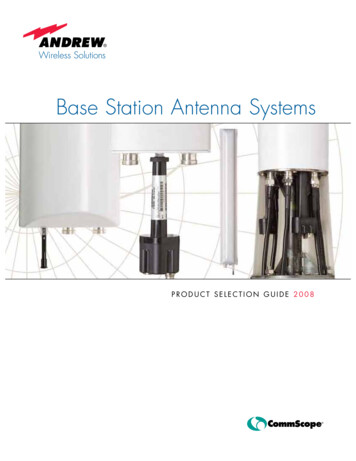
Antenna Integrated Radio Unit Description2Product OverviewAIR unit 6468 is an Advanced Antenna System (AAS).A typical configuration is shown in Figure 1.AIRBasebandG109360AFigure 12.1AIR Unit Connected to a BasebandMain FeaturesThe AIR Unit is an Advanced Antenna System with beamforming and FullDimension Multiple Input Multiple Output (FD-MIMO) technology, capable tofully utilize radio resources in both azimuth and elevation.The main benefits compared to previous macro solutions are improvements in:2 Enhance coverage - High gain adaptive beamforming Enhance capacity - High order spatial multiplexing and multi-user MIMO91/1551-LZA 701 6001/1 Uen X 2018-03-12
Product Overview Advanced RAN features - Vertical/horizontal beamforming Improved network performance - Low inter-cell interferenceThe AIR Unit is designed for outdoor installations, intended for pole, wall,tower, or mast mounting. It operates over LTE TDD radio access technology.The following are the main features of the AIR unit:2.2 2-wire power connection LTE Time Division Duplex (LTE TDD) 64 transmitter/receiver (64TX/64RX) branches 10.3 Gbps Ethernet Complies with 3GPP base station classes Wide Area. The relevantstandards are listed in Radio Standards Compliance on page 24.Required Installation EquipmentTable 1 lists the mounting kits required for the AIR unit. For more information,refer to Main-Remote Installation Products Overview.Table 1Mounting KitMounting KitProduct NameProduct NumberTilt and swivel mounting Bracket supporting AIRkitwith tilting /-30degrees and swivelingright/left 15 degreesSXK 109 1936/1Swivel mounting kitBracket supporting AIRwith swiveling right/left30 degreesSXK 109 2064/1Tilt and swivel mounting Bracket supporting AIRkitwith tilting /-20degrees and swivelingright/left 30 degreesSXK 109 2065/191/1551-LZA 701 6001/1 Uen X 2018-03-12(for B41E only)3
Antenna Integrated Radio Unit DescriptionNote:Please note and adhere to the following for safety and operationreasons: The mechanical design of AIR Unit 6468 (below the “AIRUnit”) is based on environmental conditions which are equal to orexceeding class 4.1 as specified in EN 300 019-1-4 and GR-487CORE and thereby respects the static mechanical load imposed onan AIR Unit by wind at maximum velocity. Wind loads in thisdocument are calculated with reference to wind pressure. For moreaccurate results, the specific terrain information for relevant sites andgeographical area where the AIR Unit will be installed needs to becarefully analyzed, considered and calculated according to EN1991-1-4.Pole clamps, brackets, mounting accessories and other installationmaterial or equipment specified by Ericsson in the AIR Unit productinformation documentation must be used and Ericsson s installationinstructions be complied with. In addition, it must be observed thatspecific environmental conditions that the AIR Unit becomes exposedfor, such as icing, heat, dust, dynamic stress (e.g. strain caused byoscillating support structures) or other environmental conditions thatexceed or otherwise deviate from the Environmental Characteristicson page 13, may result in the breakage of an AIR Unit or itsmounting accessories and even cause the AIR Unit to fall to theground.The above mentioned facts, information and circumstances must beconsidered and properly taken into account during the site planningprocess and adhered to for installation and operation of the AIR Unit.Ericsson expressly disclaims any responsibility or liability arising outof failures in this regard.491/1551-LZA 701 6001/1 Uen X 2018-03-12
Technical Data3Technical DataThis section describes the physical characteristics, environmental data, andthe power supply characteristics of the AIR unit.3.1Bands, Carriers, and Output PowerTable 2Bands, Carriers, and Output Power for AIR 6468DescriptionValueMaximum nominal output B41E: 120 Wpower(1) (2)B42: 120 WB41: 120 W(License key is required for total output powerover 20 W.)Number of carriersFrequency(3)LTE: up to threeB41E for LTE: 2575–2635 MHzB42 for LTE: 3400–3600 MHzB41 for LTE: 2496-2690MHz(1) Detailed information about licenses and hardware activation codes (HWAC) can be found in:LTE: Manage Licenses and Hardware Activation Codes in the Radio Node libraries.(2) Detailed information about output power can be found in applicable Output Power FeatureDescription.(3) Information about Instantaneous Bandwidth (IBW) can be found in RBS Configurations.3.2EIRP Data3.2.1Traffic BeamsThis section describes the Effective Isotropic Radiated Power (EIRP) of trafficbeams for the AIR unit.Table 3 lists the typical EIRP performance data of traffic beams.91/1551-LZA 701 6001/1 Uen X 2018-03-125
Antenna Integrated Radio Unit DescriptionTable 3AIR Unit Typical EIRP Performance Data for Traffic BeamsUniform TrafficBeams(1)DirectionsHtilt, Vtilt0 , 3 55 , 3 0 , 18 Vertical Beamwidth9.5 9.5 10 Horizontal Beamwidth12 22 12 Minimum peak EIRP(2)B41E: 2 71.5 dBmB42: 2 71.5 dBmB41: 2 71.5 dBmB41E: 2 68 dBmB42: 2 68 dBmB41: 2 68 dBmB41E: 2 70 dBmB42: 2 70 dBmB41: 2 69.5 dBm(1) The traffic beamforming of this product is not limited to the uniform beamshapes anddirections given in the table. The beams are dynamically optimized.(2) The minimum peak EIRP in the table is calculated for two simultaneous orthogonal beams.3.2.2Broadcast BeamsThis section describes performance data for broadcast beams in threedifferent scenarios.Table 4AIR Unit Typical Antenna Performance Data for Broadcast BeamsScenarioMacroHotspotHighriseBeamBrM1, BrM2(1)BrHS1, BrHS2(2)BrHR1, BrHR2(3)Vertical Beamwidth10 1 30 3 30 3 Horizontal Beamwidth65 5 65 5 20 2 Digital Downtilt[ 8, 8] Fixed 3 Fixed 3 Vertical beam pointingerror 1 3 3 Horizontal beampointing direction0 5 0 5 0 2 EIRP (max)B41E: 2 64.5 dBmB42: 2 64.5 dBmB41: 2 64.5 dBmB41E: 2 59.5 dBmB42: 2 60 dBmB41: 2 59.5 dBmB41E: 2 64 dBmB42: 2 64 dBmB41: 2 64 dBmSide Lobe Suppression16 dB (vertical)12 dB (vertical)12 dB (horizontal)Front to Back Ratio25 dB25 dB25 dBBeam Parallelity 10 dB 10 dB 10 dB(1) Broadcast Beam Macro 1, Broadcast Beam Macro 2.(2) Broadcast Beam Hotspot 1, Broadcast Beam Hotspot 2.(3) Broadcast Beam Highrise 1, Broadcast Beam Highrise 2.3.3Physical CharacteristicsThis section describes the physical dimensions, weight, and color of the AIRUnit.691/1551-LZA 701 6001/1 Uen X 2018-03-12
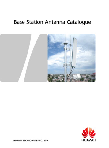
Technical DataCABG109377AFigure 2AIR Unit DimensionsTable 5AIR Unit DimensionsDescriptionValueHeight (A)B41E: 988 mmB42: 988 mmB41: 988 mmWidth (B)B41E: 520 mmB42: 520 mmB41: 520 mmDepth (C)B41E: 158 mmB42: 187 mmB41: 187 mm91/1551-LZA 701 6001/1 Uen X 2018-03-127
Antenna Integrated Radio Unit DescriptionTable 6AIR Unit WeightAIR UnitTypeWeight withoutMounting KitWeight with Mounting KitSXK 109 1936/1SXA 109 2064/1SXA 109 2065/1AIR 6468B41E46.4 kg58.1 kgN/AN/AAIR 6468B4260.4 kgN/A64.9 kg67.4 kgAIR 6468B4160.4 kgN/A64.9 kg67.4 kgThe whole body of the AIR Unit including the radome is gray, and the colorvalue is NCS S 1002-B.3.4Installation RequirementsThis section describes the installation requirements for installing the AIR Unit.For a complete installation description, refer to Install Antenna IntegratedRadio Units.The AIR Unit is only for outdoor installation, and it can be installed either on apole, or on a mast or a tower.3.4.1Outdoor Installation Environments to AvoidThe AIR unit is designed for outdoor use but to ensure optimal operation avoidthe following: Hot microclimates caused, for example, by heat radiated or reflected fromdark or metallic walls or floors Chimney mouths or ventilation system outlets Large glass or concrete surfacesAvoid radio interference by keeping the area directly in front of the antennaclear of the following:8 Metal surfaces or objects such as railings, ladders, or chains Equipment generating electromagnetic fields, for example electric motorsin air conditioners or diesel generators RBS equipment91/1551-LZA 701 6001/1 Uen X 2018-03-12
Technical DataAIR/AntennaAntenna lobeNo interfering objectsin front of the antenna!Ge8801E3.4.2Space RequirementsThe AIR unit is installed with the cable connections facing down. Allow aminimum of 500 mm free space below the AIR unit to ensure sufficient workingspace. If there is a heat generating unit placed below the AIR unit, thedistance to the AIR unit must be a minimum of 2.0 m to ensure adequateairflow.Table 7 lists the required free space needed between AIR units to ensureadequate airflow.Table 7Space Requirement for Adequate Airflow Between AIR UnitsFree Space Required Between AIR Free Space Required for AIR UnitsUnits Installed Above Each OtherInstalled Side by Side2000 mm3.4.3300 mmPainting LimitationsEricsson does not recommend painting the AIR, especially not the radome, asit may affect radio performance of the unit.Ericsson will apply limitations to the warranty and service contract if the AIR ispainted.91/1551-LZA 701 6001/1 Uen X 2018-03-129
Antenna Integrated Radio Unit DescriptionNote:3.5If the AIR needs to be painted, please contact Ericsson for additionalinformation.Installation AlternativesFigure 3 shows the installation alternatives. Figure 4 and Figure 5 show the tiltand swivel angles of different mounting kits.ABCDG110771AFigure 3Installation Method AlternativesTable 8Key to Installation AlternativesInstallation MethodDescriptionAPole installation ( pole with circular cross section)BWall installationC(1)Pole installation (pole with square cross section)D(1)Pole installation (pole with 90 angle cross section)(1) The installation method is not supported by the mounting kit for B41E.Table 910Pole Mounting Range (Mounting Kit for B41E)PoleCircular Cross SectionMinimumØ55 mmMaximumØ115 mm91/1551-LZA 701 6001/1 Uen X 2018-03-12
Technical DataTable 1030 Pole Mounting Range (Mounting Kits for B41 and B42)PoleCircular CrossSectionSquare CrossSection90 Angle CrossSectionMinimumØ76 mm50 x 50 mm50 x 50 mmMaximumØ120 mm80 x 80 mm80 x 80 mm0 3 0 15 0 0 15 Ge646816Figure 4Tilt and Swivel Angle (Mounting Kit for B41E)91/1551-LZA 701 6001/1 Uen X 2018-03-1211
Antenna Integrated Radio Unit Description1220 0 320 0 30 0 30 G110748AFigure 5Tilt and Swivel Angle (Mounting Kits for B41 and B42)Note:3.6Mounting kit SXK 109 2064/1 supports only swivel angle, and SXK109 2065/1 supports both swivel and tilt angle.Acoustic NoiseThe AIR unit is silent in normal operation status. It may emit low levels ofacoustic noise when operating on low capacity in LTE.The sound pressure level when operating on low capacity in LTE can be 28dBA at one-meter distance and hemispherical distribution, and 25 dBA forspherical distribution.1291/1551-LZA 701 6001/1 Uen X 2018-03-12
Technical Data3.7Environmental CharacteristicsThis section contains operating environment data for the AIR unit.3.7.1Operating EnvironmentTable 11Air Unit Normal Operating EnvironmentConditionValue/RangeTemperature 40 C through 55 CSolar radiation 1,120 W/m²Relative humidity2% through 100%Absolute humidity0.26 through 40 g/m3Maximum temperature change1.0 C/minMaximum wind load at 42 m/s (Pole B41E: 735 Ninstalled AIR unit)B42: 753NB41: 753N3.7.2VibrationThis section describes the tolerance of the AIR unit to vibrations. The AIR unitoperates reliably during seismic activity as specified by test method IEC60068-2-57 Ff.Maximum level of Required ResponseSpectrum (RRS)50 m/s2 within 2-5 Hz for DR 2%Frequency range1–35 HzTime history signalVerteq IIThe AIR unit operates reliably during random vibration as specified by testmethod IEC 60068-2-64 Fh method 1.Random vibration, normal operation0.3 m2/s3 on x,y-axes0.2 m2/s3 on z-axisThe AIR unit operates reliably during shock as specified by test method IEC60068-2-27 Ea.Peak acceleration40 m/s2Duration22 ms91/1551-LZA 701 6001/1 Uen X 2018-03-1213
Antenna Integrated Radio Unit Description3.7.3MaterialsAll Ericsson products fulfill the legal, market, and Ericsson requirementsregarding the following:3.8 Material declaration Materials' fire resistance, components, wires, and cables Recycling Restricted and banned material usePower Supply CharacteristicsThis section describes the power supply requirements, power consumption,and fuse and circuit breaker recommendations for the AIR unit.3.8.1DC Power Supply CharacteristicsThe power supply voltage for the AIR unit is 48 V DC.The following is a list of the power supply requirements:Nominal Voltage 48 V DCOperating Voltage RangeB41E: 40.0 to 58.5 V DCB42: 38.0 to 58.5 V DCB41: 38 to 58.5V DCNon-destructive Range0 to 60 V DCThe AIR unit is designed for 2-wire power connections.Fuse and Circuit Breaker RecommendationsThe recommended fuse and circuit breaker rating is minimum 35 A andmaximum 45 A.The recommendations given in this section are based on peak powerconsumption: no information on power consumption during normal operation isavailable.The recommended melting fuse type is am-gL-gG, according to IEC 60269-1.Circuit breakers must comply with at least Curve 3 tripping characteristics,according to IEC 60934.The AIR unit has a built-in Class 1 (Type 1) Surge Protection Device (SPD) toprotect the equipment in case of lightning and network transients. The1491/1551-LZA 701 6001/1 Uen X 2018-03-12
Technical Datarecommended fuse or circuit breaker rating is therefore dimensioned to not tripthe fuse or circuit breaker during typical SPD operations.3.8.2Power ConsumptionFor information on power consumption, refer to Power Consumption Guidelinefor RBS 6000.3.9System CharacteristicsThis section describes the system characteristics of the AIR system.3.9.1RF Electromagnetic Exposure for RBS 6000For general information on RF Electromagnetic Fields (EMF) for AIR unitsconnected to an RBS from the 6000 family, refer to Radio FrequencyElectromagnetic Fields.Information about radio access-specific compliance boundaries forelectromagnetic exposure, refer to Radio Frequency ElectromagneticExposure.3.9.2SoftwareInformation on software dependencies can be found in Radio SoftwareSupport.3.9.3Radio ConfigurationsFor information about available radio configurations, refer to RBSConfigurations.91/1551-LZA 701 6001/1 Uen X 2018-03-1215
Antenna Integrated Radio Unit Description4Hardware ArchitectureThis section describes the AIR unit hardware structure regardless ofconfiguration or frequency. For a description of the currently available radioconfigurations, refer to RBS Configurations.4.1AIR Unit PartsCBADGe646801BFigure 6Table 1216AIR Unit PartsAIR Unit PartsPositionComponentARadomeBUpper lifting eye91/1551-LZA 701 6001/1 Uen X 2018-03-12
Hardware Architecture4.2PositionComponentCGrids for cooling, air inlet, and outletDConnection interfacesOptical IndicatorsThe AIR unit is equipped with optical indicators that show the system status.The location of the optical indicators is shown in Figure 7.Table 13 describes how to interpret the optical indicators on the AIR unit. Fordetailed information about the optical indicators, refer to Indicators, Buttons,and Switches.The AIR unit has no maintenance button.Note:121AB C2DGe646803Figure 7Table 13PositionABCOptical IndicatorsOptical IndicatorsMarkingIndicatorColorModeFaultRedOffNo fault detected in unitOnFault detected in unitOffNo powerOnOperationalFlashing Slowly(0.5 Hz)Missing dependent resourceFlickering (16Hz)Transitory activityDouble flashingOffLoading in progressNo ongoing trafficDouble flashingOnLoading in progressTraffic is ongoingOffNo ongoing maintenance activityTraffic is ongoingOperationalMaintenance91/1551-LZA 701 6001/1 Uen X 2018-03-12GreenBlueInterpretation17
Antenna Integrated Radio Unit ColorGreenModeInterpretationOnMaintenance modeAll traffic and alarms are suppressedFlashing Slowly(0.5 Hz)Maintenance mode is initiatedWhen traffic and alarms are removed, theindicator switches to OnOffDisconnectedOnConnected91/1551-LZA 701 6001/1 Uen X 2018-03-12
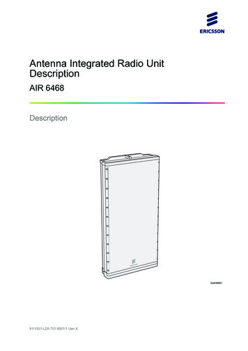
Connection Interfaces5Connection InterfacesThe AIR Unit connection interfaces are shown in Figure 8 and are listed inTable 14.12AHFGEDCBGe646803AFigure 8Table 14AIR Unit Connection InterfacesAIR Unit Connection InterfacesPositionDescriptionMarkingAGrounding pointB 48 V DC power supplyCOptical cable 22DOptical cable 11ConnectorTypesConnector Illustration2 x M6 bolt 48 V91/1551-LZA 701 6001/1 Uen X 2018-03-12Power connectorLC (On SFP) withsupport for FullAXS19
Antenna Integrated Radio Unit sEOptional synchronizationtimingAUXLC (On SFP) withsupport for FullAXSFExternal alarm/EC lightinterface(1)GOptical indicatorsDIN 14 femaleconnector–,1,HConnector Illustration–,2TX MonitorB41E: N-type femaleconnectorB42: SMA femaleconnectorB41: SMA femaleconnector(1) The EC functionality is for all bands of AIR 6468, while the external alarm functionality is only for B41E.5.1Grounding InterfaceThe AIR unit must be grounded to protect it from overvoltage and lightningstrikes. The grounding interface on the AIR unit accepts an M6 dual cable lugon a coated cable.For more information about grounding principles, refer to GroundingGuidelines for RBS Sites.5.2 48 V DC Power Supply InterfaceThe 48 V DC power connection is made through a connector with a 2-wireconnection. The connector accepts cables with various cross-sectional areasdepending on the cable length as shown in Table 15.2091/1551-LZA 701 6001/1 Uen X 2018-03-12
Connection InterfacesTable 15 48 V DC Power Supply CableCable Length (m)Cross-Sectional Areaof Each Conductor(mm2)Note0–4010Used with connectorRNT 447 32/02 or RNT447 38/02 for B41EUsed with connectorRNT 447 38/02 for otherbands40–6016Used with connectorRNT 447 32/03 or RNT447 38/03 for B41EUsed with connectorRNT447 38/03 for otherbands60–90Note:25Used with junction boxNTB 101 75/1The power cable connectors don't support hot plug.The power cable conductor has a wire for both the 0 V conductor and a wirefor the 48 V DC conductor.All cables must be shielded. The shielding must be properly connected both tothe power connector and to the grounding in the power supply equipment;otherwise, the AIR unit over voltage and lightning protection does not functionproperly.5.3Interface for Optical CableThe optical cable interfaces provide connections to optical cables for trafficand timing signals between the AIR and a Baseband unit. A Small Form-factorPlugable (SFP) is used to connect the optical cable to the AIR.Note:The AIR uses SFP modules for optical transmission and opticalradio interfaces on Data 1 and Data 2.Only use SFP modules approved and supplied
Mar 12, 2018 · Table 6 AIR Unit Weight AIR Unit Type Weight without Mounting Kit Weight with Mounting Kit SXK 109 1936/1 SXA 109 2064/1 SXA 109 2065/1 AIR 6468 B41E 46.4 kg 58.1 kg N/A N/A AIR 6468 B42 60.4 kg N/A 64.9 kg 67.4 kg AIR 6468 B41 60.4 kg N/A 64.9 kg 67.4 kg The whole body of the AIR Unit inclu