Transcription
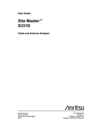
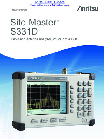
To buy, sell, rent or trade-in this product please click on the link and-Antenna-Analyzer.aspxwww.avionteq.comSite Master S331D/S332DCable and Antenna AnalyzerSite Master is the preferred cable and antenna analyzer ofwireless providers, contractors and installers.Color display option shownS331D Site MasterSiteMasterMS2712SiteMasterMS2711D Spectrum MasterMS2712SpectrumMasterSpectrumMasterMT8212A Cell MasterMS2712CellMasterCellMasterUser’s Guide
WARRANTYThe Anritsu product(s) listed on the title page is (are) warranted against defects inmaterials and workmanship for one year from the date of shipment.Anritsu's obligation covers repairing or replacing products which prove to be defective during the warranty period. Buyers shall prepay transportation charges forequipment returned to Anritsu for warranty repairs. Obligation is limited to the original purchaser. Anritsu is not liable for consequential damages.LIMITATION OF WARRANTYThe foregoing warranty does not apply to Anritsu connectors that have failed due tonormal wear. Also, the warranty does not apply to defects resulting from improper orinadequate maintenance by the Buyer, unauthorized modification or misuse, or operation outside the environmental specifications of the product. No other warranty isexpressed or implied, and the remedies provided herein are the Buyer's sole andexclusive remedies.TRADEMARK ACKNOWLEDGMENTSWindows, Windows 95, Windows NT, Windows 98, Windows 2000, Windows MEand Windows XP are registered trademarks of the Microsoft Corporation.Anritsu, FlexCal, InstaCal and Site Master are trademarks of Anritsu Company.NOTICEAnritsu Company has prepared this manual for use by Anritsu Company personneland customers as a guide for the proper installation, operation and maintenance ofAnritsu Company equipment and computer programs. The drawings, specifications,and information contained herein are the property of Anritsu Company, and any unauthorized use or disclosure of these drawings, specifications, and information isprohibited; they shall not be reproduced, copied, or used in whole or in part as thebasis for manufacture or sale of the equipment or software programs without theprior written consent of Anritsu Company.UPDATESUpdates to this manual, if any, may be downloaded from the Anritsu internet site at:http://www.us.anritsu.com.Equipment marked with the Crossed-out WheelieBin symbol complies with the EuropeanParliament and Council Directive 2002/96/EC (the“WEEE Directive”) in the European Union.For Products placed on the EU market afterAugust 13, 2005, please contact your local Anritsurepresentative at the end of the product's usefullife to arrange disposal in accordance with yourinitial contract and the local law.June 2007Copyright ã 2003-2007 Anritsu Co.10580-00079Revision: H
Table of ContentsChapter 1 - General InformationIntroduction . . . . . . . . . . . . . . . . . . . . . . . . . . . . . . . . . . 1-1Description . . . . . . . . . . . . . . . . . . . . . . . . . . . . . . . . . . . 1-1Standard Accessories . . . . . . . . . . . . . . . . . . . . . . . . . . . . . 1-1Options . . . . . . . . . . . . . . . . . . . . . . . . . . . . . . . . . . . . . 1-2Printers . . . . . . . . . . . . . . . . . . . . . . . . . . . . . . . . . . . . . 1-3External Detectors . . . . . . . . . . . . . . . . . . . . . . . . . . . . . . . 1-3Optional Accessories. . . . . . . . . . . . . . . . . . . . . . . . . . . . . . 1-4Performance Specifications . . . . . . . . . . . . . . . . . . . . . . . . . . 1-6Preventive Maintenance . . . . . . . . . . . . . . . . . . . . . . . . . . . 1-12Calibration . . . . . . . . . . . . . . . . . . . . . . . . . . . . . . . . . . 1-12InstaCal Module . . . . . . . . . . . . . . . . . . . . . . . . . . . . . . 1-13Annual Verification. . . . . . . . . . . . . . . . . . . . . . . . . . . . . . 1-13ESD Precautions . . . . . . . . . . . . . . . . . . . . . . . . . . . . . . . 1-13Mode References . . . . . . . . . . . . . . . . . . . . . . . . . . . . . . . 1-13Chapter 2 - Functions and OperationsIntroduction . . . . . . . . . . . . . . . . . . . . . . . . . . . . . . . . . . 2-1Test Connector Panel . . . . . . . . . . . . . . . . . . . . . . . . . . . . . 2-1Display Overview . . . . . . . . . . . . . . . . . . . . . . . . . . . . . . . 2-3Front Panel Overview . . . . . . . . . . . . . . . . . . . . . . . . . . . . . 2-4Function Hard Keys . . . . . . . . . . . . . . . . . . . . . . . . . . . . . . 2-5Keypad Hard Keys . . . . . . . . . . . . . . . . . . . . . . . . . . . . . . . 2-6Soft Keys. . . . . . . . . . . . . . . . . . . . . . . . . . . . . . . . . . . . 2-8Power Monitor, External Detector (Option 5) . . . . . . . . . . . . . . . . 2-38Transmission Measurement (Option 21) . . . . . . . . . . . . . . . . . . . 2-39Interference Analyzer Mode (Option 25). . . . . . . . . . . . . . . . . . . 2-46Channel Scanner Mode (Option 27) . . . . . . . . . . . . . . . . . . . . . 2-55CW Signal Generator Mode (Option 28) . . . . . . . . . . . . . . . . . . . 2-58Power Meter Menus (Option 29) . . . . . . . . . . . . . . . . . . . . . . . 2-61T1 Tester Mode Menus (Option 50) . . . . . . . . . . . . . . . . . . . . . 2-63E1 Tester Mode Menus (Option 50) . . . . . . . . . . . . . . . . . . . . . 2-66Symbols. . . . . . . . . . . . . . . . . . . . . . . . . . . . . . . . . . . . 2-68Self Test . . . . . . . . . . . . . . . . . . . . . . . . . . . . . . . . . . . 2-69Error Messages . . . . . . . . . . . . . . . . . . . . . . . . . . . . . . . . 2-70Battery Information. . . . . . . . . . . . . . . . . . . . . . . . . . . . . . 2-75Charging a New Battery . . . . . . . . . . . . . . . . . . . . . . . . . . 2-75Determining Remaining Battery Life. . . . . . . . . . . . . . . . . . . . 2-76Important Battery Information . . . . . . . . . . . . . . . . . . . . . . . 2-79Chapter 3 - Getting StartedIntroduction . . . . . . . . . . . . . . . . . . . . . . . . . . . . . . . . . . 3-1Power On Procedure . . . . . . . . . . . . . . . . . . . . . . . . . . . . . 3-1Cable and Antenna Analyzer Mode . . . . . . . . . . . . . . . . . . . . . . 3-2Spectrum Analyzer Mode . . . . . . . . . . . . . . . . . . . . . . . . . . 3-11All Modes. . . . . . . . . . . . . . . . . . . . . . . . . . . . . . . . . . . 3-15Save and Recall a Setup . . . . . . . . . . . . . . . . . . . . . . . . . . 3-15Save and Recall a Display . . . . . . . . . . . . . . . . . . . . . . . . . 3-15i
Changing the Units . . . . . . . .Changing the Language. . . . . .Adjusting Markers . . . . . . . .Adjusting Limits . . . . . . . . .Adjusting the Display Brightness.Printing . . . . . . . . . . . . . . .Using the Soft Carrying Case. . . .3-163-163-163-173-183-193-20.Chapter 4 - Cable and Antenna Analyzer MeasurementsIntroduction . . . . . . . . . . . . . . . .Line Sweep Fundamentals . . . . . . . . .CW Mode/RF Immunity . . . . . . . . .Information Required for a Line Sweep .Typical Line Sweep Test Procedures . .4-14-14-24-34-3Chapter 5 - Spectrum Analyzer MeasurementsIntroduction . . . . . . . . . . . . . . . . . . . . . . . . . . . . . . . . . . 5-1Measurement Fundamentals . . . . . . . . . . . . . . . . . . . . . . . . . . 5-1Preamplifier . . . . . . . . . . . . . . . . . . . . . . . . . . . . . . . . . . 5-3Preamplifier Operation. . . . . . . . . . . . . . . . . . . . . . . . . . . . 5-3Preamplifier Measurement Example. . . . . . . . . . . . . . . . . . . . . 5-4Dynamic Attenuation Control . . . . . . . . . . . . . . . . . . . . . . . . . 5-6Frequency Converter Interface (Option 6). . . . . . . . . . . . . . . . . . . 5-7Introduction . . . . . . . . . . . . . . . . . . . . . . . . . . . . . . . . . 5-7Selecting the Signal Standard and Channel . . . . . . . . . . . . . . . . . . 5-8Field Strength Measurements . . . . . . . . . . . . . . . . . . . . . . . . 5-9Occupied Bandwidth . . . . . . . . . . . . . . . . . . . . . . . . . . . . . 5-10Channel Power Measurement. . . . . . . . . . . . . . . . . . . . . . . . 5-12Adjacent Channel Power Ratio . . . . . . . . . . . . . . . . . . . . . . . 5-14Interference Analysis . . . . . . . . . . . . . . . . . . . . . . . . . . . . . 5-16AM/FM Demodulation . . . . . . . . . . . . . . . . . . . . . . . . . . . . 5-17Demodulation Procedure . . . . . . . . . . . . . . . . . . . . . . . . . . 5-17Carrier to Interference Ratio (C/I) . . . . . . . . . . . . . . . . . . . . . . 5-19Procedure . . . . . . . . . . . . . . . . . . . . . . . . . . . . . . . . . . 5-19Chapter 6 - Internal Power Meter ModeIntroduction . . . . . . . . . . . . . . . . . . . . . . . . . . . . . . . . . . 6-1Power Measurement . . . . . . . . . . . . . . . . . . . . . . . . . . . . . . 6-1Offset Calibration . . . . . . . . . . . . . . . . . . . . . . . . . . . . . . 6-2Chapter 7 - Power Monitor ModeIntroduction . . . . . . . . . . . . . . . . . . . . . . . . . . . . . . . . . . 7-1Power Measurement . . . . . . . . . . . . . . . . . . . . . . . . . . . . . . 7-1Chapter 8 - High Accuracy Power MeterIntroduction . . . . . . . . . . . . . . . . . . . . . . . . . . . . . . . . . . 8-1Power Measurement . . . . . . . . . . . . . . . . . . . . . . . . . . . . . . 8-2ii
Chapter 9 - T1 MeasurementsIntroduction . . . . . . . . . . . . . . . . . . . . . . . . . . . . . . . . . . 9-1T1 Fundamentals. . . . . . . . . . . . . . . . . . . . . . . . . . . . . . . . 9-1G.821 Measurement Definitions . . . . . . . . . . . . . . . . . . . . . . . . 9-2Network Equipment . . . . . . . . . . . . . . . . . . . . . . . . . . . . . . 9-2Testing T1 Circuits. . . . . . . . . . . . . . . . . . . . . . . . . . . . . . . 9-4In Service Testing . . . . . . . . . . . . . . . . . . . . . . . . . . . . . . 9-4Out-Of-Service Testing . . . . . . . . . . . . . . . . . . . . . . . . . . . 9-7DS0 Testing. . . . . . . . . . . . . . . . . . . . . . . . . . . . . . . . . 9-12Chapter 10 - E1 MeasurementsIntroduction . . . . . . . . . . . . . . . . . . . . . . . . . . . . . . . . . . 10-1E1 Fundamentals . . . . . . . . . . . . . . . . . . . . . . . . . . . . . . . 10-1G.821 Measurement Definitions . . . . . . . . . . . . . . . . . . . . . . 10-2Network Equipment . . . . . . . . . . . . . . . . . . . . . . . . . . . . . 10-2Testing E1 Circuits . . . . . . . . . . . . . . . . . . . . . . . . . . . . . . 10-3In Service Testing . . . . . . . . . . . . . . . . . . . . . . . . . . . . . 10-3Out-Of-Service Testing . . . . . . . . . . . . . . . . . . . . . . . . . . . 10-8VF Channel Access Testing . . . . . . . . . . . . . . . . . . . . . . . . 10-11Chapter 11 - Transmission MeasurementIntroduction . . . . . . . . . . . . . . .Measuring Active Devices . . . . . . .Calibration . . . . . . . . . . . . . . .Transmission Measurement Procedure .Bias Tee (Option 10A) . . . . . . . . 113-313-413-5Chapter 12 - GPS FeatureIntroduction . . . . . . . . . .Activating the GPS Feature. .Saving with GPS InformationRecalling GPS Information . .Chapter 13 - Interference Analyzer ModeIntroduction . . . . . .Interference Analysis .Spectrogram . . . . .Signal Strength . . . .RSSI . . . . . . . . .Signal ID . . . . . . .Chapter 14 - Channel Scanner ModeIntroduction . . . . . . . . . . . . . . . . . . . . . . . . . . . . . . . . . 14-1Channel Scanner . . . . . . . . . . . . . . . . . . . . . . . . . . . . . . 14-1Chapter 15 - Signal Generator ModeIntroduction . . . . .Required EquipmentProcedure . . . . . .Softkeys. . . . . . .15-115-115-115-2iii
Chapter 16 - Handheld Software ToolsIntroduction . . . . . . . . . . . . . . . . . . . . . . . . . . . . . . . . . . 16-1Features . . . . . . . . . . . . . . . . . . . . . . . . . . . . . . . . . . . . 16-1System Requirements. . . . . . . . . . . . . . . . . . . . . . . . . . . . . 16-1Installation . . . . . . . . . . . . . . . . . . . . . . . . . . . . . . . . . . 16-2Using Handheld Software Tools . . . . . . . . . . . . . . . . . . . . . . . 16-3Downloading Traces . . . . . . . . . . . . . . . . . . . . . . . . . . . . 16-3Plot Capture to the PC . . . . . . . . . . . . . . . . . . . . . . . . . . . 16-4Plot Upload to the Instrument . . . . . . . . . . . . . . . . . . . . . . . 16-4Plot Properties . . . . . . . . . . . . . . . . . . . . . . . . . . . . . . . 16-4Signal Standards Editor . . . . . . . . . . . . . . . . . . . . . . . . . . 16-11Appendix A - Reference DataCoaxial Cable Technical Data. . . . . . . . . . . . . . . . . . . . . . . . . A-1Appendix B - WindowingIntroduction . . . . . . . . . . . . . . . . . . . . . . . . . . . . . . . . . B-1Examples . . . . . . . . . . . . . . . . . . . . . . . . . . . . . . . . . . B-1Appendix C - Signal StandardsIntroduction . . . . . . . . . . . . . . . . . . . . . . . . . . . . . . . . . C-1IndexѻકЁ᳝ ᳝ᆇ 䋼 ܗ ⱘৡ ঞ 䞣 䚼ӊৡ 䪙 3E J For Chinese Customers OnlyYLYB᳝ ᳝ᆇ 䋼 ܗ 䬝 ݁Ӌ䫀 ⒈㘨㣃 ⒈Ѡ㣃䝮 &G &U Ď @ 3%% 3%'( ƻhॄࠋ㒓䏃ᵓ h h ƻ ƻ 3& ᴎ ǃᬃᶊ h ƻ h h ƻ ƻ &KDVVLV /&' h h h h ƻ ƻ ݊Ҫ 㓚ǃ亢 ǃh ƻ h h ƻ ƻ 䖲 ㄝ SSHQGHG JRRGV ƻ 㸼 䆹᳝ ᳝ᆇ 䋼 䆹䚼ӊ᠔᳝ഛ䋼ᴤ᭭Ёⱘ 䞣ഛ 6- 7 ᷛ ޚ 㾘ᅮⱘ䰤䞣㽕 ҹϟDŽ h 㸼 䆹᳝ ᳝ᆇ 䋼㟇ᇥ 䆹䚼ӊⱘᶤϔഛ䋼ᴤ᭭Ёⱘ 䞣䍙ߎ 6- 7 ᷛ ޚ 㾘ᅮⱘ䰤䞣㽕 DŽ ⦃ֱՓ ᳳ䰤䖭Ͼᷛ䆄ᰃḍ ݀ᏗⱘNj ᄤֵᙃѻક ᶧ ࠊㅵ⧚ njҹঞ6- 7 Nj ᄤֵᙃѻક ᶧ ࠊᷛ䆚㽕 njⱘ㾘ᅮˈ䗖 Ѣ Ё 䫔ଂⱘ ᄤֵᙃѻકⱘ⦃ֱՓ ᳳ䰤DŽҙ䰤Ѣ 䙉ᅜ䆹ѻકⱘᅝܼ㾘㣗ঞՓ ᛣџ乍ⱘ ⸔ϞˈҢ ѻ᮹䍋ㅫⱘ䆹ᑈ䰤 ˈݙ ϡӮ ѻક᠔ ᳝ᆇ 䋼ⱘ さথᗻবᓖˈ㗠ᇍ⦃๗ ᶧˈҎ䑿ঞ䋶ѻѻ ࠏ ᕅડDŽ ⱘ
The Site Master model S332D includes Spectrum Analysis (100 kHz - 3 GHz) and has dedicated routines for common one-button measurements. Options available with the S331D or S332D include 2-port Transmission Measurements, Bias Tee, narrow band or wide band power meter, Channel Scanner, Interference Analyzer, GPS, and T1/E1 Analyzer measurements. The displayed trace can be scaled or