Transcription
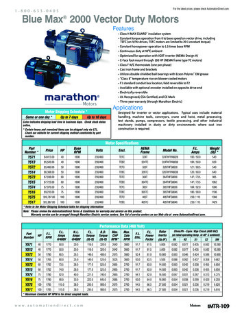
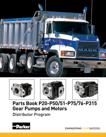
Service Application ManualSAM Chapter 650-004Section 6AELECTRONICALLY COMMUTATED MOTORSPart 2: Constant-Airflow ECMsby Christopher MohalleyGenteq Certified Master ECM TrainerCONSTANT-AIRFLOW, VARIABLE-SPEED (OEM)INDOOR BLOWER ECMsThe constant-airflow (variable-speed) ECM wasintroduced in 1987 by GE (rebranded Genteq in2009). It was the first and only indoor blower ECMuntil the introduction of the constant-torque ECM in2006. The term “variable-speed motor” was coined inthe late 1980s. By function it is a “constant-airflowmotor.” Both of these terms define the type or styleof ECM and how it is programmed to function.Variable-speed motors are built in 1 3-, 1 2-, 3 4-,and 1-hp sizes, and only in direct-drive designs.These motors have gone through many generationalimprovements in their more than 20 years ofexistence, including advances in reliability andcommunication formats, as well as changes in theirphysical appearance. This chapter covers only thecurrent-generation motors.The three main benefits of these motors overconventional induction (PSC) motors are: increased electrical efficiency more precise and unlimited airflow selection(the “variable-speed” feature)Motor module16-pin ECM modelControl moduleMotor module4-pin ECM modelCOURTESY OF GENTEQ Control moduleFigure 1. Construction of variable-speed ECMs 2010 by the Refrigeration Service Engineers Society, Des Plaines, ILSupplement to the Refrigeration Service Engineers Society.1
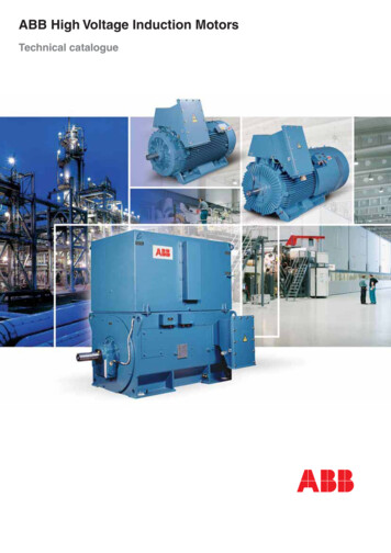
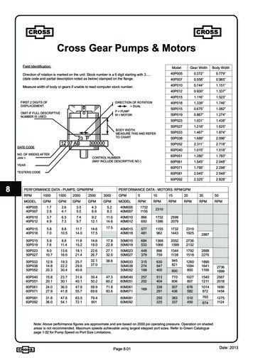
properly maintained airflow during changes insystem static pressure (the “constant-airflow”feature).The ECMs shown in Figure 1 on the previous pageare actually built as two separate components. Thecontrol module (motor control), with its own shell orhousing, is attached to the back of the motor module(motor). The variable-speed motor control isprogrammed to provide constant airflow. This isaccomplished by converting the desired cfm to aspecific speed (rpm) and torque (current) deliveredto the motor.Each HVAC OEM (original equipment manufacturer)creates a special program unique to the model andsize unit in which the variable-speed ECM will beused. This program provides multiple airflow andcomfort options for each demand of the system inwhich the motor is installed, and any of the possibleconnected components.COURTESY OF GENTEQ To summarize: The variable-speed motor is operatedby two programs. The HVAC OEM programdetermines the amount of airflow needed by demand,and the constant-airflow program makes sure thatthe selected airflow is maintained even if externalstatic pressure changes. The constant-airflowprogramming is unique to each OEM by model andsize of appliance. No two variable-speed motors areprogrammed alike.OPERATIONThe variable-speed ECM is a dual-voltage motor. The120-V ac or 240-V ac single-phase power is suppliedthrough the 5-pin connector to the motor at all times,even if there is no demand for airflow (see Figure 2).This power is what operates the internal electronicsand drives the motor. The low-voltage or serialcommunication that is sent to the motor from theOEM control board through the 16-pin or 4-pinconnector is a combination of the OEM programming,the installer’s selection of airflow and comfort settings,and the current demand of the HVAC system (heat,cool, fan, etc.). This is the information that the motorcontrol (microprocessor) requires to determine howmuch torque and speed the motor will need in orderto supply the proper airflow for each systemdemand.During each demand, the motor control alsomonitors the actual speed in revolutions perminute (rpm) of the motor. There is only onecombination of torque and speed that willcreate the proper cfm demanded at a specifictotal ESP (external static pressure) of thesystem. If the speed/torque relationship isincorrect for the required airflow, the motorcontrol can increase or decrease the torque(current) to the motor. This, in turn, willincrease or decrease the speed of the motorto maintain airflow. By constantly monitoringthe actual speed of the motor, and maintainingthe torque/speed relationship programmed bythe HVAC OEM, the motor control is able tomaintain the airflow selection per demand ifthe total ESP tion4-pinconnectionFigure 2. Electrical connections2Three very important points must beunderstood about this motor’s ability tomaintain a constant airflow:
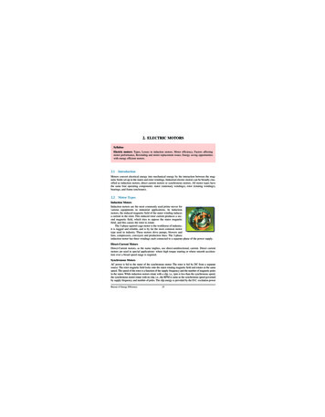
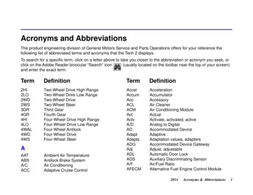
PSC LOPSC MEDPSC HI170016001500Airflow, cfm2. The motor requires less energy tomaintain airflow when the total ESPis equal to or less than the HVACOEM recommendation, and the airnoise of the system will be decreased.ECM3. The motor has a programmed limit ofoperation to protect itself from damage,due to the energy (current) it must use tomaintain airflow if the total ESP gets too high.Consult the HVAC OEM literature to find therecommended maximum total ESP. If the systemexceeds the HVAC OEM recommendation, airflowmay not be maintained—however, the motor willstill try to deliver as much air as possible, withoutcausing damage to itself.APPLICATION AND BENEFITSVariable-speed motors are typically found in twostage, multi-stage, and modulating high-end furnaces(80 % and 90 % AFUE), air handlers, packagesystems, and geothermal systems.Constant airflow is the ability of the variable-speedmotor to maintain its programmed and field-selectedairflow per demand, even when the total ESP ishigher than recommended and/or changes duringsystem operation. The total ESP (the resistance tothe movement of air) is increased when ductwork isundersized, poorly constructed, and/or full of dirt ordebris. The total ESP can increase during systemoperation when dirt builds up on the air distributionsystem components (especially the filter), and whencustomers close or block grilles and registers.The variable-speed motor is programmed to maintainairflow during all of these situations, within the limitsof the OEM programming and motor design. Bycontrast, torque (current) and airflow will decreasewhen the total ESP increases in PSC induction motorsystems (see Figure 3).140013001200110010009000.00.20.40.6Total ESP, in. w.g.0.81.0Figure 3. Airflow vs. total ESPWhen set up correctly, the benefits of the variablespeed motor system include: energy savings improved outlet air temperature for each systemdemand improved humidity control improved system capacity reduced space temperature swings reduced air noise with soft start/stop and gradualchanges between airflow demands, delays, and/orprofiles reduced constant fan air noise with low cfmsettings, plus increased energy savings overnormal system operation reduced repairs associated with continuous lowairflow operation.INSTALLATION AND SETUPAfter the system is installed, the technician mustfollow the HVAC OEM’s instructions in selectingthe proper airflow and comfort settings to match thecomponents and desired operation. These settings aretypically selected by using jumper pins, dip switches,and/or multi-pin plugs on the OEM control board3COURTESY OF GENTEQ 1. The motor requires more energy tomaintain airflow when the total ESPis higher than the HVAC OEMrecommendation, and the air noiseof the system may be increased.
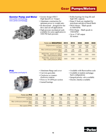
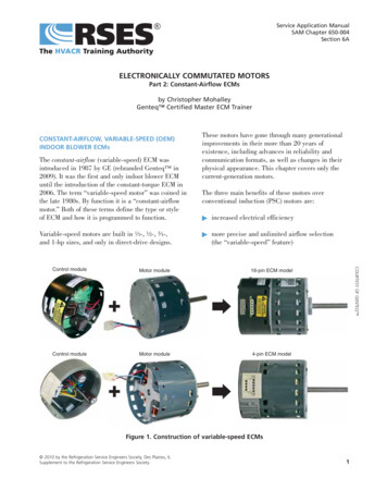
COURTESY OF GENTEQ Dip switchesON 1234567and a setting on the control board in the OEM systemto initiate the feature.8Jumper pinsHEATCOOLADELAYAADJUSTANORM( )BBBCCC(–)DDDTESTRotary switchfor delay timeRotary switch forcooling tonnageModel plugs forheating selection435It is recommended that the electrical connections onthe ECM be facing downward, or between the 4 and8 o-clock positions, and a drip loop formed out ofthe wiring harness leaving the motor (see Figure 6).This prevents any moisture or water that may getinto the motor area from running into the connectors,where it could cause damage to the control. In mostsystems, the OEM installs the motor in the correctposition and provides the drip loop. However, whenmulti-position systems are installed in a positionother than the manufactured position, the motormay need to be turned and the drip loop rearranged.X2XFigure 4. Control board options(see Figure 4). There are also some systems in whichmany of these selections can be adjusted at the userinterface. (In these systems, the user interfacereplaces the thermostat as the communication centerfor the system.) If these selections are not set at thetime of installation, there is a good chance that thesystem will not perform as expected and/or notproduce the designed capacity. In addition, thesystem may be prone to problems and/or prematureparts failures.Figure 5 shows several examples of HVAC OEMairflow and comfort charts. The trim/adjust airflowchart allows the cooling airflow to be tweaked up ordown to increase the sensible or latent capability ofthe cooling system. The climate/delay profile chartsare designed to enhance the cooling cycle by climatefor either more dehumidification or OFF-cycle cooling.Another comfort option that greatly enhancesdehumidification uses an external humidistat. Thehumidistat provides a demand to the HVAC systemthat is transferred to the motor to decrease the airflowduring the cooling cycle. This type of on-demanddehumidification typically requires a separatehumidistat or thermostat/humidistat combination,4The total ESP of the installed system should bemeasured and compared to the OEM charts. If it isabove the maximum listed for that unit, improvementsshould be made to lower it. Any total ESP below themaximum is typically acceptable. However, systemefficiency, noise levels, and potential service issuesall will be improved when the total ESP is as close tothe OEM recommendation as possible. The OEM’sinstallation manuals provide guidelines that shouldbe followed per unit for best performance. Someimportant examples of the guidelines found in thesemanuals include filter-sizing charts, proper ductconnections, and unit cutouts.The temperature rise in fossil-fuel systems shouldalways be measured and corrected if it is not withinthe OEM rating listed on the data plate of the givenunit.Note: Water damage is one of the most frequentlyrecurring failures associated with electricalcomponents. Always construct and size thecondensate drains and traps according to OEMspecifications.TROUBLESHOOTINGBefore troubleshooting any HVAC system, it’s agood practice to become familiar with the systemcomponents and wiring diagram. Check for andfollow any on-board diagnostics (OEM system faultcodes). When you’re working on a variable-speed
COURTESY OF GENTEQ Figure 5. Typical HVAC OEM airflow andcomfort chartssystem, you should also check the airflow, comfort,and delay settings. Typically you will need to consultthe HVAC OEM manuals for these settings. Themanufacturer’s literature can also provide valuablesequence-of-operation and troubleshooting help. Check the airflow settings using the HVAC OEMguide. Check the air distribution system components fordirt load and closed dampers, registers, andgrilles. Measure the total ESP and make the necessaryrepair(s) if it is above the maximum levelrecommended by the HVAC OEM. Aftermarketfilter sizing is a common issue.COURTESY OF GENTEQ If the motor is running but the system is noisy,shutting down on its limits or safeties, or theevaporator coil is freezing, there is a good chancethat the problem is most likely external to the motorand the motor itself is good.Be aware, too, that thermostat (control) wiring isvery important. HVAC equipment manufacturershave many different connection diagrams for theoperation of multi-stage furnaces and air handlerswith single-stage or multi-stage thermostats andoutdoor units. Often there are circuit board settingsthat correspond to the type of connection andoperation as installed. If the control wiring andUpBack of motor controlConnectors facingdownward between4 and 8 o’clock positionsWiring harnessformed into drip loopFigure 6. Drip loop5
COURTESY OF GENTEQ 12Jumperconnectedbetweenterminals1and 21No jumper23Ground3Ground4Neutral4120-V ac L25120-V ac L15120-V ac L1Meter connected betweenterminals 4 and 5Meter connected betweenterminals 4 and 5Figure 7. Checking the high-voltage inputsettings are not done properly, the system may runonly in one stage and/or be operating at the wrongairflow per stage.First check the high-voltage input to the 5-pinconnector. Depending on the system, there should be120 V ac or 240 V ac at terminals 4 and 5 wheneverthere is power to the system, regardless of a demandcall (see Figure 7). If there is no high-voltage input,fix the problem in the system before proceeding. For120-V ac systems, make sure that the polarity of thepower connected to the motor is correct. If the highvoltage reading is within 15% of the rated voltage,move on to the next step. If the reading is higher orlower than 15% of the rated voltage, fix the voltageproblem first, then try to run the motor again. Alwayscheck for proper grounding and repair if needed.COURTESY OF GENTEQ If the motor is not running, the following checks willhelp you diagnose whether it is operational. Alwaysdisconnect the power to the HVAC system beforedisconnecting or reconnecting any connectors to themotor. There are two inputs needed to operate thistype of motor—a high-voltage constant power source,and the communication input that selects the airflowrequirement per demand. All of the connectors/plugsused with the motor are keyed for proper orientation.If connected improperly, the motor may not operateproperly and/or it may be damaged.Step 1. Check the high-voltage inputRCHVACsystemboard24-V actransformerFigure 8. Using the TECMate PRO6
COURTESY OF GENTEQ Note: As shown in Figure 7, 120-V ac motors musthave a jumper connected between terminals 1 and 2for proper operation. To prevent damage, 240-V acmotors should not have this jumper.16-pin4-pinStep 2. Check the communication inputTo check the communication to the motor on the16-pin or 4-pin connector, you will need to have theHVAC system’s OEM manual showing pin-by-pinwhat voltage/communication
the ECM be facing downward, or between the 4 and 8 o-clock positions, and a drip loop formed out of the wiring harness leaving the motor (see Figure 6). This prevents any moisture or water that may get into the motor area from running into the connectors, where it could cause damage to the control. In most