Transcription
Additive ManufacturingN. SinhaDepartment of Mechanical EngineeringIIT Kanpur
DefinitionAdditive Manufacturing (AM) refers to a process by whichdigital 3D design data is used to build up a component in layersby depositing material.(from the International CommitteeManufacturing Technologies, ASTM).F42forAdditiveWhat You See Is What You Build (WYSIWYB) ProcessDifference between Rapid Prototyping and Additive Manufacturing?
Additive vs Subtractive Manufacturing Part Complexity; Material; Speed; Part Quantity; Cost.
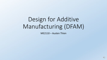
Additive vs Subtractive ManufacturingFigure: Features that represent problems using CNC machining.Source: Gibson, Additive Manufacturing
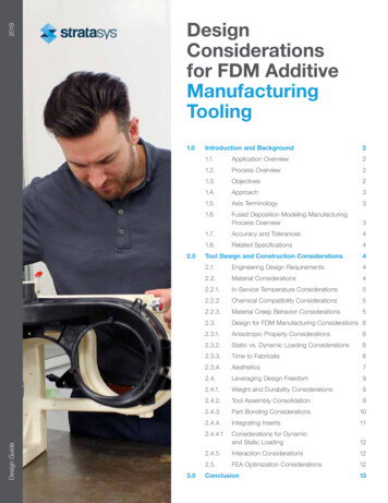
Generic AM ProcessSource: Gibson, Additive Manufacturing
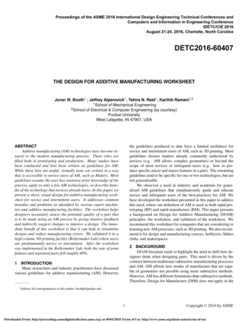
CAD Model into STL FormatSTL uses triangles to describe the surfaces to be built. Each triangle isdescribed as three points and a facet normal vector indicating the outwardside of the triangle, in a manner similar to the following:facet normal 4.470293E02 7.003503E01 7.123981E-01outer loopvertex 2.812284E 00 2.298693E 01 0.000000E 00vertex 2.812284E 00 2.296699E 01 1.960784E02vertex 3.124760E 00 2.296699E 01 0.000000E 00endloopendfacetSource: Gibson, Additive Manufacturing
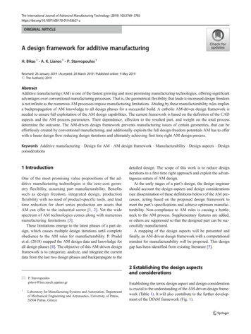
Generic AM ProcessEffects of building using different layer thicknessesSource: Gibson, Additive Manufacturing
Other Related Technologies1. Reverse engineering technology2. Computer aided engineering (CAE):3D CAD model Engineering analysis software packages3. Haptic-based CADSource: Gibson, Additive Manufacturing
Difference between various AM techniques? Techniques used for creating layers; Techniques of bonding the layers together; Speed; Layer thickness; Range of materials; Accuracy; Cost.
EvolutionSource: Royal Academy of Engineering
EvolutionSource: Royal Academy of Engineering
SourceGoogle imagesCurrent and Potential industries for Additive Manufacturing
Pros and Cons
BenefitsSource: SAVING project/Crucible Industrial Design Ltd.; Roland Berger
BenefitsSource: Roland Berger
BenefitsSource: Roland Berger
Future: Home ManufacturingOld toothbrushCustomization: Bristle hardness Colour Handle Style and shape Etc.New toothbrushLaser scanner to inputpersonalized dataHome 3D Printer
Case StudiesSource: Royal Academy of Engineering
Introduction to Reverse EngineeringThe primary input for AM is CAD file/model.Suppose that for a part (to be copied, modified orrepaired) CAD was not used in the original design; there is inadequate documentation on the originaldesign; the original CAD model is not sufficient to supportmodification or manufacturing using modern methods; the original supplier is unable or unwilling to provideadditional parts.
Introduction to Reverse Engineering“Examining competitive or similar or prior products in greatdetail by dissecting them or literally taking them apart.”- Dym & LittleTechnological principles of a device through analysis of itsstructure, function and operation.“What does this do?”“How does it do that?”“Why would you want to do that?”
Introduction to Reverse EngineeringPurposes solved Dissection and analysis Experience and knowledge for an individual’s personaldatabase Competitive benchmarking
Introduction to Reverse EngineeringReverse Engineering Process1. Digitizing the partsThis step uses a reverse engineering device to collect rawgeometry of the object.The data is usually in the form of coordinate points ofthe object relative to a local coordinate system.2. Building CAD modelsThis step converts the raw point data obtained from step1 into a usable format.Physical partPhysicalpartPhysicalpartCADmodelPhysical partpartPrototype
Example
General Integration of an AM Machine
Material itesPolymersa) ABS polymerb) Acrylicsc) Cellulosed) Nylone) Polycarbonatef) Thermoplastic polyesterg) Polyethyleneh) Polypropylenei) Polyvinylchloride
Thermal Expansion Characteristics
Load-Displacement CharacteristicsMetalsPolymersMetals: Characterized by a linear elastic region followed by a non-linear plasticregion.Polymers: Generally brittle at temperatures much lower than Tg, but their ductility increasesas temperature rises. As the temperature increases to levels above Tg, a peak load is reached and a neckbegins to form. As the specimen approaches its fracture point, the load rises due to the stretchingof molecules.
Material ClassificationMetalsa) Pure metals: Ti, Ta, Cu, Au, Agb) Alloys: Ti-based, Ni-based, Fe-based, Al-based, Co-based, Cu-based
Material/process considerations and controlmethodsAbsorptanceProcesses of AM generally involve a direct interaction of powders withlaser beam. The determination of absorptance of powders isparticularly important to thermal development, because it allows one todetermine a suitable processing window free of a non-response ofpowder due to an insufficient laser energy input or a pronouncedmaterial evaporation due to an excessive energy input.The absorptance is defined as the ratio of the absorbed radiation to theincident radiation. The absorptance of powders has a direct influenceon the optical penetration depth δ of the radiation, which is defined asthe depth at which the intensity of the radiation inside the material fallsto 1/e ( 37%) of the original value. Owing to the multiple reflectioneffect, the δ measured in powders is larger than in bulk materials.
Surface tension and wettabilityThe liquid–solid wetting characteristics are crucial for a successful AMprocess. The wetting behaviour of a partially melted LS system involves thewetting between structural metal and liquid binder as well as the wettingbetween the molten system and the solidified preprocessed layer. For thecompletely melted LM/LMD systems, the second kind of wettingbehaviour prevails.The wetting of a solid by a liquid is related to the surface tension of solid–liquid ߛsl, solid–vapour ߛsv and liquid–vapour ߛlv interfaces. Wettability canbe defined by the contact angle ߠThe liquid wets the solid as cosߠ - 1. A spreading coefficient has beendefined in literatureto describe the wetting behaviour and, normally, a large positive S favoursspreading of the liquid.
ViscosityBesides the favourable wettability, it is required that the viscosity of the melt islow enough such that it successfully spreads on the previously processed layerand, in the case of LS, surrounds the solid structural particles. For a LS systemconsisting of a solid–liquid mixture, the viscosity of the molten material µ isexpressed aswhere µ0 is the base viscosity that includes temperature terms, Φl is the volumefraction of liquid phase and Φm is a critical volume fraction of solids abovewhich the mixture has essentially infinite viscosity. As to an LM or LMDsystem with a complete liquid formation, the dynamic viscosity of the liquid isdefined bywhere m is the atomic mass, k the Boltzmann constant, T the temperature andߛ the surface tension of the liquid.
CeramicsAM technology has been successfully demonstrated its advantages inproducing ceramic parts through both “direct” and “indirect”methods.Indirect Methods These processes typically create a ceramic green body with ahigh content of organic or inorganic binders. Then, binder burnout and densification of the green body areconducted in a conventional sintering step.Example: A ZrB2 part (fuel injector strut for aircraft engine),alumina and silica cores and shells for investment casting, graphitebipolar plates for fuel cells, and bio-ceramic bone scaffolds werefabricated using SLS by laser scanning the mixture of ceramicpowder and binder and then removing the binder and sintering theparts in a furnace.
CeramicsDirect MethodsDirect fabrication of ceramic parts using AM processes is muchmore challenging due to the high melting temperatures ofceramics such as Al2O3 ( 2000 C) and SiO2 ( 1700 C), andalso the large thermal gradients, thermal stresses and residualstresses associated with melting/resolidifying in the laser basedAM processes.Example: SLM process was investigated to fabricate ceramic partsfrom a mixture of zirconia and alumina by completely melting theceramic powder. The ceramic powder bed was preheated to atemperature higher than 1600 C to reduce thermal stresses, andnearly fully dense, crack-free parts were obtained without any postprocessing. Fully dense, net-shaped, alumina parts were producedusing LENS by direct laser melting of the ceramic powder.
Composites Composites are engineered or naturally occurring materials made from two ormore constituent materials with significantly different physical or chemicalproperties that remain separate and distinct at the macroscopic or microscopicscale within the finished structure but exhibit properties that cannot be achievedby any of the materials acting alone. The materials in a composite can be mixed uniformly, resulting in ahomogeneous compound (uniform composite), or non-uniformly, resulting inan inhomogeneous compound (e.g., functionally graded materials) in which thecomposition varies gradually over volume, leading to corresponding changes inthe properties of the composite material.
CompositesUniform Composites Uniform composites fabricated using AM processes are usually done byemploying a pre-prepared mixture of proper materials, such as a mixed powderbed for SLS, SLM and 3DP, a filament in mixed materials for FDM, a compositelaminate for LOM, or a mixture of liquid photocurable resin with particulates forSLA. The composite materials that can be produced with AM technology include apolymer matrix, ceramic matrix, metal matrix, and fiber and particulate reinforcedcomposites. Metal-metal composites (e.g., Fe-Cu and stainless steelCu), metal-ceramiccomposites (e.g., WC-Cu, WC-Co, WC-CuFeCo, TiC-Ni/Co/Mo, ZeB2-Cu, andTiB2-Ni), and ceramic-ceramic composites (e.g., Si-SiC) have been processed bySLS/SLM. These processed composites can be classified into two categories: those thataim to facilitate the process using a liquid-phase sintering mechanism, and thosethat combine various materials to achieve properties not possible with a singlematerial.
CompositesUniform Composites Examples of composites in the first category include Fe-Cu and stainless steelCu used in SLS, in which Cu acts as a binder to bond Fe or stainless steel particlesrather than a reinforcement phase to enhance the mechanical or other propertiesof the final product. An example of the second category is the bio-composite poly-epsiloncaprolactone and hydroxyapatite (PCL/HA) bone scaffold fabricated using SLS,with the addition of HA to enhance the strength and biocompatibility of PCL. By developing a feedstock filament with the proper composite, polymer-metaland polymer-ceramic composites could be produced with FDM. ABS-Ironcomposites have been made using FDM with a single-screw extruder byappropriately producing an iron particulate-filled polymeric filament. Fibers, suchas short glass fibers and nanofibers (vapor-grown carbon fibers), have been addedinto ABS filaments to improve the mechanical properties of the parts built usingFDM.
Composites: Functionally Graded MaterialsStepwise Graded StructuresAn example is a spark plug which gradient is formed by changing itscomposition from a refractory ceramic to a metalContinuous Graded Structures An example is the human bone which gradient is formed by itschange in porosity and composition; Change in porosity happens across the bone because of miniatureblood vessels inside the bone.
Functionally Graded Materials (FGMs)FGMs can be obtained bylayeredmixingoftwomaterials of different thermomechanical properties withdifferent volume ratio bygradual changing from layerto layer.
Composites: Functionally Graded MaterialsThe human bone is a an example of a FGM. It is a mixof collagen (ductile protein polymer) and hydroxyapatite(brittle calcium phospate ceramic).A gradual increase in the pore distribution from theinterior to the surface can pass on properties such asshock resistance, thermal insulation, catalytic efficiency,and the relaxation of the thermal stress.Thedistribution of the porosity affects the tensile strengthand the Young’s modulus.
Composites: Functionally Graded MaterialsCurrent applications of FGMs include: Structural walls that combine two ormore functions including thermal andsound insulation; Enhanced sports equipment such as golfclubs, tennis rackets, and skis with addedgradedcombinationsofflexibility,elasticity, or rigidity; Enhancedbodycoatingsforcarsincluding graded coatings with particlessuch as dioxide/mica.
AM Unique CapabilitiesVarious types of nano/microstructurescan be achieved by careful control of theprocess parameters (e.g. laser power, scanrate) for a particular material, and canvary from point to point within astructure.The ability to simultaneously control a part's nano/microstructure,mesostructure, and macrostructure simply by changing processparameters and CAD data is a capablity of AM which is unparalleledusing conventional manufacturing.
AM Unique Capabilities When building parts in an additive manner, one always has access tothe inside of the part. Component can be inserted and it is possible to fabricate operationalmechanisms in some AM processes.Pulley-driven snake-like robotSource: Gibson.
AM Unique CapabilitiesThe concept of functionally graded materials, or heterogeneous materials, hasreceived considerable attention.However, manufacturing useful parts from these materials often has beenproblematic.Example: Turbine blade for a jet engineI. The outside of the blade must be resistant to high temperature and verystiff to prevent elongation;II. The blade root must be ductile and has high fatigue life;III. Blade interiors must have high heat conductivity so that the blades can becooled.A part with complex shape that requires different material properties indifferent regions.No single material is ideal for this range of properties.A significant issue hindering the adoption of AM’s material complexityis the lack of design and CAD tools that enable representation andreasoning with multiple materials.
Process Planning in Layered Manufacturing
Process Planning in Layered ManufacturingThere are four main planning tasks:(i) orientation optimization,(ii) support design,(iii) slicing, and(iv) tool-path/scanning-path planning.
Sample STL FileAdvantages and Disadvantages?
STL FileAdvantages(i) Provides a simple method of representing 3D CAD data(ii) A de facto standard and has been used by most CAD systems andRP systems(iii) It can provide small and accurate files for data transfer for certainshapesDisadvantages(i) The STL file is many times larger than the original CAD data file(ii) The geometry flaws exist in the STL file(iii) The subsequent slicing of large STL files can take many hours
STL File Problems
Valid vs. Invalid Tessellated Models
STL File Repair
Stereolithography One of the most important additive manufacturing technologiescurrently available. The first ever commercial RP systems were resin-based systemscommonly called stereolithography or SLA. The resin is a liquid photosensitive polymer that cures or hardenswhen exposed to ultraviolet radiation. This technique involves the curing or solidification of a liquidphotosensitive polymer through the use of the irradiation lightsource. The source supplies the energy that is needed to induce achemical reaction (curing reaction), bonding large no of smallmolecules and forming a highly cross-linked polymer.
The UV light comes from a laser,which is controlled to scan acrossthe surface according to thecross-section of the part thatcorresponds to the layer. The laser penetrates into theresin for a short distance thatcorrespondstothelayerthickness. The first layer is bonded to aplatform, which is placed justbelow the surface of the resincontainer. The platform lowers by one layerthickness and the scanning isperformed for the next layer. Thisprocess continues until the parthas been completed.
A part produced by stereolithography (Source: 3D Systems, Inc.).
Facts About STL Each layer is 0.076 mm to 0.50 mm (0.003in to 0.020 in.) thick– Thinner layers provide better resolution and moreintricate shapes; but processing time is longer Starting materials are liquid monomers Polymerization occurs on exposure to UVlight produced by laser scanning beam– Scanning speeds 500 to 2500 mm/s
Part Build Time in STLTime to complete a single layer :AiTi TdvDwhere Ti time to complete layer i; Ai area of layer i; v average scanning speed of the laser beam at the surface;D diameter of the “spot size,” assumed circular; and Td delay time between layers to reposition the worktable
Part Build Time in STL - continuedOnce the Ti values have been determined for all layers,then the build cycle time is:nlTc Tii 1where Tc STL build cycle time; and nl number of layersused to approximate the part Time to build a part ranges from one hour for smallparts of simple geometry up to several dozen hours forcomplex parts
Numerical ProblemA prototype of a tube with a square cross-section is to befabricated using stereolithography. The outside dimensionof the square 100 mm and the inside dimension 90 mm(wall thickness 5 mm except at corners). The height ofthe tube (z-direction) 80 mm. Layer thickness 0.10 mm.The diameter of the laser beam (“spot size”) 0.25 mm,and the beam is moved across the surface of thephotopolymer at a velocity of 500 mm/s. Compute anestimate for the time required to build the part, if 10 s arelost each layer to lower the height of the platform that holdsthe part. Neglect the time for postcuring.
Numerical Problem: SolutionLayer area Ai is same for all layers.Ai 1002-902 1900 mm2.Time to complete one layer Ti is same for all layers.Ti (1900 mm2)/(0.25 mm)(500mm/s) 10 s 25.2 sNumber of layersnl (80 mm)/(0.10 mm/layer) 800 layersTc 800(25.2) 20,160 s 336.0 min 5.6 hr
How layer by layer adhesion takes placein stereolithography?The new layer adheres to the previous one because thedepth of penetration of each pulse of laser is greater thanthe thickness of the layer and hence over cures the priorlayer.This process is repeated as many times as is necessary torecreate the entire object layer by layer. When completed,the platen is raised from the vat and the model is ready forremoval of the support structure and postcuring.
CAD was not used in the original design; there is inadequate documentation on the original design; the original CAD model is not sufficient to support modification or manufacturing using modern methods; the original sup