Transcription
A Handbook forSuccessful VoIPDeployment: NetworkTesting, QoS, and MoreContentsMeasuring Call QualityObjectively. 2Testing VoIP Call Quality . 5Getting your Data NetworkReady for VoIP. 6Summary . 12Copyright Information . 13by John Q. Walker, NetIQ Corporationjohnq@netiq.comDeploying Voice over IP (VoIP) successfully in an enterprisedata network has some unexpected pitfalls. In previous papers,we’ve explored how to do a Voice Readiness Assessment [1] andsummarized key planning and design tips [2,3]. This paperdescribes changes to improve how a data network handles VoIPtraffic – that is, how you can reduce one-way delay, jitter, anddata loss for VoIP traffic, while retaining the performance ofyour other business-critical network applications.Copyright NetIQ Corporation 2002.1
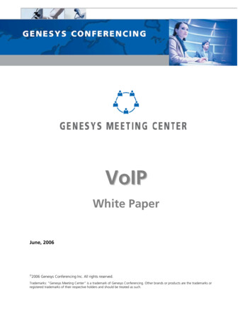
Data networks haven’t traditionally been reported on using a single metric, since there aremany factors to consider. Yet, in thetelephony world, a single number is typicallygiven to rate voice call quality. Voice over IP(VoIP) spans the two worlds: it’s a data network application, yet the quality of VoIP conversations is reflected in a single metric uponwhich to benchmark, trend, and tune.Call quality measurement has traditionallybeen subjective: picking up a telephone andlistening to the quality of the voice. Theleading subjective measurement of voicequality is the MOS (mean opinion score) asdescribed in the ITU (International Telecommunications Union) recommendation P.800[4]. MOS comes from the telephony worldand is the widely accepted criterion for callqualityIn using MOS with human listeners, a groupof people listen to audio and give their opinion of the call quality. This certainly workswell, but asking people to listen to calls overand over can be difficult and expensive to setup and execute. You can also guess that it’sinconvenient to have a bunch of peoplestanding around each time you make a network tuning adjustment. The good news isthat the human behavioral patterns have beenheavily researched and recorded. ITU P.800describes how humans react – what score theywould give – as they hear audio with differentaspects of delay or datagram loss.Measuring Call QualityObjectivelyConsiderable progress has been made in establishing objective measurements of callquality. Various approaches have beendeveloped: PSQM (ITU P.861) / PSQM : PerceptualSpeech Quality Measure MNB (ITU P.861): Measuring NormalizedBlocks PESQ (ITU P.862): Perceptual Evaluationof Speech QualityCopyright NetIQ Corporation 2002. PAMS (British Telecom): PerceptualAnalysis Measurement System The E-model (ITU G.107)PSQM, PSQM , MNB, and PESQ are part of asuccession of algorithm modifications startingin ITU recommendation P.861. BritishTelecom developed PAMS, which is similar toPSQM. The PSQM and PAMS measurementssend an analog reference signal through thetelephony network and then compare thereference signal with the signal that’s receivedon the other end of the network, by means ofdigital signal processing algorithms. Severaltraditional voice measurement tools have implemented PSQM and PAMS measurements.These measurements are good in test labs foranalyzing the clarity of individual devices; forexample, it makes sense to use PSQM to describe the quality of a telephone handset.Vendors that implement these scoring algorithms all map their scores to MOS.However, these approaches are not really wellsuited to assessing call quality on a data network in an enterprise. They’re based in theolder telephony world, so the data network istreated as a big analog black box. They require invasive hardware probes, which youneed to purchase and deploy before beginningVoIP measurements. The models used are notbased on data network issues, so they can’tmap back to the network issues of delay, jitter,and datagram loss. Their output doesn’tdirect the network staff how to tune. Also,they aren’t suited to the two-waysimultaneous flows of a real phone conversation, and they don’t scale to let you evaluatethe quality of hundreds or thousands ofsimultaneous calls.ITU recommendation G.107 [5] defines the “Emodel.” The E-model is a complex formula;the output of an E-model calculation is a single score, called an “R factor,” derived fromdelays and equipment impairment factors.Once an R factor is obtained, it can be mappedto an estimated MOS. R factor values rangefrom 100 (excellent) down to 0 (poor); a MOScan range from 5 down to 1. An estimatedMOS can be directly calculated from the Emodel’s R factor.2
Figure 1. R factor values from the E-model are shown on the left, with their corresponding MOS values on theright. The likely satisfaction level of human listeners is shown in the middle.Software, like NetIQ’s Vivinet Assessor, testcall quality by generating real-time transportprotocol (RTP) streams that mimic VoIPtraffic. The RTP traffic flows between twoendpoints in a data network. Each time a testis run, measurements are collected for the oneway delay time, the number of datagrams lost,the number of consecutive datagrams lost, andthe amount of variability in the arrival time ofthe datagrams (known as jitter). These measurements can capture in a MOS what’s important for voice quality: how the two peopleat the two telephones perceive the quality oftheir conversation.We recommend using the E-model for doingvoice-readiness testing of a data network. TheE-model provides a powerful and repeatableway to assess whether a data network is readyto carry VoIP calls well. The E-model showsus that there are two ways that a digitizedvoice signal can be impaired as it passesthrough a data network. It can be impaired bydelay and it can be impaired by the equipmentthat sits between the talker and the listener.For VoIP, this equipment is the codecs at thetwo ends and everything in the data networkthat sits between them. To improve voicequality, we need to reduce the impairmentsthat occur. Let’s look at each kind of impairment separately: delay impairment andequipment impairment.Propagation DelayThe physical distance between the twoends of the data network determines howlong it takes to propagate a signal betweenthem. This delay is proportional to thespeed of light, that is, the time needed bythe physical signal as it passes throughcopper, optical, or wireless media. There’smuch more propagation delay betweenNew York City and Sydney than there isbetween New York City and Boston.Transport DelayEvery networking device between thetalker and listener introduces some delay.It takes time to get through every router,firewall, traffic shaper, and other deviceon the route. For some devices, like hubs,this delay is relatively constant. For otherdevices, particularly routers, the delay canincrease as the amount of other traffic andcongestion increase in a network.Packetization DelayCodecs take time to convert analog signalsto digital packets and vice versa. A highspeed codec like G.711 does this packetization quickly, in about one millisecond.Low-speed codecs take much longer, sincethey do compression to reduce the packetsize. Codecs in the G.723 family introduce67.5 milliseconds of delay in theirconversion from analog signals to digitalpackets.Delay ImpairmentsFour components comprise the total one-waydelay between a talker and a listener:Copyright NetIQ Corporation 2002.3
CodecNominalData Rate(kbps)PacketizationDelay a5.367.5Figure 2. Common voice codecs and the one-waydelay they introduce.Jitter Buffer DelayWhen there’s a lot of variation in the arrival time of VoIP datagrams, a jitter buffercan be introduced to smooth the playback.Rather than converting VoIP packets directly back to analog as they arrive, one ortwo packets are held in memory at thelistener’s side. The codec there retrievesits next packet to convert from the jitterbuffer, so it is always one or two packets“behind.” When some delay occurs, thecodec can be playing from the currentpacket in memory, not waiting for apacket to arrive. When excessive delayoccurs, however, packets may need to besimply discarded, to make way for thenext arriving packet.The amount of packetization and jitter bufferdelay are determined at the time you deployyour VoIP equipment. You decide on whichcodec to use and you decide the size of thejitter buffer. The other two delay componentscan be tuned, to some degree, to reduce thetotal one-way delay. Although you can’t decrease the absolute propagation time betweenNew York City and Sydney, there may be detours in the route between them. You mightsee that the VoIP datagrams are not taking adirect route between the two locations – andtune the network for a more direct route.Transport delay is the most variable delaycomponent, and one most amenable to tuning.You can readily determine the latency at eachhop under low-load conditions and see wherethe most time is being spent. You can alsolook at the latency under heavy-load, highstress conditions, and tune the amount of delay introduced by congestion and other traffic.Copyright NetIQ Corporation 2002.Equipment ImpairmentsMany test tools are available in the telephonymarketplace to determine how the quality ofanalog audio signals are impaired. These areuseful when working with the analog portionof the signal path, for example, how good thehandset sounds.Our focus here, though, is on what happens inthe data network. Impairment of the digitizedsignal in a data network occurs in just twoways. It can occur in the codecs, when the Ato-D and D-to-A conversions occur, and it canoccur because of lost datagrams in the datanetwork. Everything between one codec andthe other is treated as one big, analog blackbox that degrades the audio signal to somedegree.Codec ImpairmentLow speed codecs impair the quality ofthe audio signal much more than highspeed codecs, because they compress thesignal with lossy compression. Fewer bitsare sent, so the receiving side does its bestto approximate what the original signalsounded like. The following table showshow much the codec impairment subtractsdirectly from the R factor, which starts at100 and can go down to 0.CodecNominalData Rate(kbps)Amountsubtracted fromthe R 19Figure 3. Common voice codecs and how theydirectly impair the E-model’s R factor.Data Loss ImpairmentVoIP packets are sent using RTP, the realtime transport protocol. Although everyRTP datagram contains a sequence number, there isn’t enough time to retransmitlost datagrams. Any lost datagram impairs the quality of the audio signal.There are two primary reasons why RTPdatagrams are lost in a data network:4
1) there’s too much traffic, so datagramsare discarded during congestion, or2) there’s too much delay variation, sodatagrams are discarded because theyarrive at the listener’s jitter buffer toolate or too early.There are a couple of patterns to datagramloss. The simplest is when there’s a moreor-less random loss. There’s general, consistent congestion in the network, so oneor two datagrams are lost occasionally.The other loss pattern is when packets arelost in bursts, say five or more at a time.Humans perceive that bursts of loss impair signal quality much more thangeneral, random loss.So, the issues in improving voice quality comedown to three: reducing total one-way delay in eachdirection, reducing delay variation (which leads toexcess jitter, and hence packet loss), and reducing overall packet loss (especiallybursts of loss).Testing VoIP CallQualityThe process of examining a data network tosee if it’s ready to support good-quality voicesignals is called doing a ”VoIP ReadinessAssessment.” A VoIP Readiness Assessmentis done in stages, starting with a simple testand getting more advanced:1. One call: Determine the voice quality of asingle call, in two directions.2. Many calls: Determine the voice quality ofeach call, during peak call volume.3. Many calls on a busy network: Determinethe voice quality of each call, during peakcall volume with heavy backgroundtraffic.can deploy VoIP successfully. Can you affordthe network equipment upgrades and tuningnecessary to carry the VoIP traffic well?If the first stage indicates the network’s readynow, you’ll want to understand its capacity tosee how many calls can be supported. Askyour local PBX management team for detailson the peak number telephone calls, whenthese occur, and what the call duration is. Usethese details to create a more complex assessment. Replicate the test setup created fordoing a single call. Run the test for a oneminute period, a few times during the daywhere your research shows heavy activity.Test five conversations at a time for a minute;what happens to the MOS estimates? Next tryten, then twenty concurrent conversations.Plot the results on a graph; you should start tosee the point where, as the number of callsincreases, the quality decreases. Don’t killyour data network during prime time bystress testing its capacity. However, start toform the graphs showing how many conversations can be supported with good quality.Understand the results at each of the threestages of a VoIP Readiness Assessment beforemoving on to the next. What’s the quality ofeach concurrent VoIP conversation? If thequality is low, what underlying network attribute contributes most to the reducedquality: one-way delay, jitter, random packetloss, and/or bursts of packet loss?If, after completing the third stage –examining the peak number of calls duringheavy network usage – the assessment indicates the voice quality will be acceptable,you’re ready to proceed with your VoIPdeployment.However, in our experience, it’s likely yourdata network won’t deliver the call qualityyou would like. In fact, a recent estimate predicted that 85% of today’s router-based datanetworks are not ready for toll-quality VoIPcalls. The remainder of this paper describessteps to consider for upgrading and tuning thenetwork.In assessing a network’s readiness for voice,the first step is to determine how well the network handles one VoIP conversation. If theMOS indicates low voice quality, it’s time tostop and consider your next steps. The datanetwork clearly needs to improve before youCopyright NetIQ Corporation 2002.5
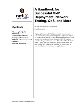
BandwidthGetting your DataNetwork Ready for VoIPReal bandwidth consumption by VoIP calls ishigher that it first appears. The G.729 codec,for example, has a data payload rate of 8 kbps.Its actual bandwidth usage is higher than this,though. When sent at 30ms intervals, its payload size is 30 bytes per datagram. To this addthe 40 bytes of RTP header (yes, the header isbigger than the payload) and any additionallayer 2 headers. For example, Ethernet adds18 more bytes. Also, there are two concurrentG.729 RTP flows (one in each direction), sodouble the bandwidth consumption you’vecalculated so far. Here’s a table showing atruer picture of actual bandwidth usage forfour common codecs.If the call quality you determined in yourVoIP Readiness Assessment isn’t adequate,determine what the problems are and wherethey’re located. What’s the biggest cause ofthe poor call quality: one-way delay, jitter,packet loss, or a combination of all three?Where are the most likely bottlenecks?Many kinds of improvements can be made toan existing data network to improve callquality. Choices include adding more bandwidth, upgrading or replacing existing network equipment, laying out your networkarchitecture in an improved manner,reconfiguring or tuning the network for QoS,or a combination of these.CodecNominalDataRate(kbps)DataBytes width for2 flows 1m6.3248243.73G.723.1a5.3207841.60Figure 4. Common voice codecs and the LAN bandwidth requirements for a two-way VoIP conversation. Totaldatagram size includes a 40-byte IP/UDP/RTP header and an 18-byte Ethernet header.You can see quickly a good rule of thumb:estimate 160 kbps bandwidth consumption foreach VoIP conversation using the G.711;estimate about 50 kbps when using one of thelow-speed codecs.Use the peak number of calls to determine rawbandwidth requirements for concurrent VoIPcalls. If you want to support 10 concurrentVoIP calls using the G.711 codec with no silence suppression, you’ll need about 1.6 Mbpsof bandwidth to support these calls on a givennetwork segment (10 x 158.93kbps – the totalbandwidth consumption of the two RTPflows). Add this additional bandwidth requirement to the existing bandwidth usage ofthe network to set the new base requirement.Here are four tuning techniques worth exploring to conserve and ration bandwidth:Copyright NetIQ Corporation 2002.compressed RTP, silence suppression, framepacking, and call admission control.Compressed RTP headers save bandwidth byreducing the number of bytes in RTP datagrams. VoIP traffic uses RTP to encapsulatethe speech frames. RTP header compression(called “cRTP”) is used among routers in thenetwork backbone. It can reduce the 40-byteRTP headers to a tenth of their original size,halving the bandwidth consumed when usinglow-speed codec. In streaming video, in contrast, the payload is often ten times the size ofthe header, so compression may not be noticeable. Enable it when there’s a link on theroute bandwidth lower than 500 kbps. So,why not always use cRTP? It adds latency,increasing the transport delay component ofthe one-way delay.6
Silence suppression saves bandwidth bymaking the payload smaller. In most telephone conversations, there are times whenone speaker or the other (or both) are silent.During silence, it’s not necessary to send fullpackets; a much smaller packet can be sent,indicating that is silence during the period. Byenabling silence suppression at each end ofthe conversation, 50% of the payloads cantypically small.RTP multiplexing can save bandwidth byputting multiple packets of audio informationinto one datagram. This means that only oneIP/UDP/RTP header is necessary, instead ofone for each audio packet. Delay is increased,though, since the datagram can’t be sent untilmultiple packets have been generated. Also,the loss of a single datagram can mean the lossof multiple audio packets, further eroding thecall quality.Using call admission control lets you avoidhaving too many concurrent VoIP conversations. If your WAN bandwidth only supportstwo VoIP calls well, you want to avoid a thirdcall. Call manager software can limit thenumber of concurrent conversations to a predefined number, to avoid overloading slowlinks.These four techniques may help, but it mayultimately come down to the fact that youneed to have bigger pipes. Look for the slowest links or the links where there is the mostcontention for bandwidth. Many delay anddata loss problems can be solved by havinglots of available bandwidth, to accommodatethe VoIP conversations and the otherconcurrent network transactions effortlessly.Equipment UpgradesUpgrading or replacing your local networkequipment may give you the boost you need,without buying additional bandwidth fromyour service provider. The latest, fastestequipment often can increase bandwidth, decrease latency, and increase capacity. Here aresome upgrades to consider:Hubs can often be bottlenecks in a heavilyused LAN. Consider replacing hubs withmodern high-speed switches. Recent switchesare also much better at handling IP multicasttraffic than those of a few years ago; be sure toCopyright NetIQ Corporation 2002.see if the combination of old switches and IPmulticast could be massively throttling youravailable LAN capacity.Routers operate using queues for the arrivingand departing traffic. Routers always seem tofunction better with lots of RAM. Doubling ortripling a router’s RAM may be a cost-effectiveupgrade.Modern hardware-based firewalls have muchhigher capacities than some older, softwarebased models. Firewalls are often bottlenecks,
Deploying Voice over IP (VoIP) successfully in an enterprise data network has some unexpected pitfalls. In previous papers, . the output of an E-model calculation is a sin-gle score, called an “R factor,” derived from . Bandwidth Data Data .