Transcription
AutomateResponder LCSecurity and Remote StartInstallation GuideThis product is intended for installation by a professionalinstaller only! Attempts to install this product by a person other than a trained professional may result in severedamage to a vehicle’s electrical system and components. 2012 Directed, Vista, CAN5304A 2012-07
Bitwriter , Code Hopping , Doubleguard , ESP , FailSafe , Ghost Switch , Learn Routine , Nite-Lite , NuisancePrevention Circuitry, Revenger , Silent Mode , Soft Chirp ,Stinger , Valet , Vehicle Recovery System , VRS , andWarn Away are all Trademarks or Registered Trademarks ofDirected.TheBitwriter (p/n998U) requires chipversion 2.7 or newer toprogram this unit.Bitwriters with a date code of 6a or older require an IC upgrade (p/n998M). Some bitwriters with a date code of 6B do not require the ICupgrade, refer to tech tip # 1112 for more information.
ContentsWarning! safety first. 4Wiring Diagram. 5Wiring Connections. 6Main Harness, 6-pin connector . 6Auxiliary/Shutdown Harness, 24-pin connector . 6Remote Start, 10-pin connector. 7Door Lock, 3-pin connector. 7Wiring Descriptions. 7Main Harness, 6-pin connector. 7Auxiliary/Shutdown Harness, 24-pin connector. 8Remote Start, 10-pin connector. 11Door Lock, 3-pin connector. 12Light Flash Polarity Setting. 12Adjusting the Sensor. 13Initializing Virtual Tach (not needed w/hardwire tach inputs). 13Learning the Tach (not needed with Virtual Tach). 14Neutral safety switch interface. 14Testing the neutral safety switch. 14Remote Start Shutdown/Startup Diagnostics. 15Remote Pairing. 16Reset and Deletion. 17Programming System Features. 18Feature Menus. 19Menu 1 - Security. 19Menu 2 - Convenience. 21Menu 3 - Remote start. 23Bitwriter - Only Options. 25Basic Remote Functions. 27Long Term Event History. 27Table of Zones. 28Troubleshooting: Alarm. 28Troubleshooting: Remote Start. 29
Warning! safety first The following safety warnings must be observed at all times:Due to the complexity of this system, installation of this product must only be performed by an authorizedDirected dealer.When properly installed, this system can start the vehicle via a command signal from the remote control.Therefore, never operate the system in an area that does not have adequate ventilation.The following precautions are the sole responsibility of the user; however, authorized Directed dealers should: Never use a test light or logic probe when installing this unit. Always use a multimeter. Never operate the system in an enclosed or partially enclosed area without ventilation (such as a garage). When parking in an enclosed or partially enclosed area or when having the vehicle serviced, the remotestart system must be disabled using the installed toggle switch. It is the user’s sole responsibility to properly handle and keep out of reach from children all remote controls to assure that the system does notunintentionally remote start the vehicle. USER MUST INSTALL A CARBON MONOXIDE DETECTOR IN OR ABOUT THE LIVING AREA ADJACENTTO THE VEHICLE. ALL DOORS LEADING FROM ADJACENT LIVING AREAS TO THE ENCLOSED OR PARTIALLY ENCLOSED VEHICLE STORAGE AREA MUST REMAIN CLOSED AT ALL TIMES.Use of this product in a manner contrary to its intended mode of operation may result in property damage,personal injury, or death. Except when performing the Safety Check outlined in this installation guide, (1)Never remotely start the vehicle with the vehicle in gear, and (2) Never remotely start the vehicle with thekeys in the ignition. The user is responsible for having the neutral safety feature of the vehicle periodicallychecked, wherein the vehicle must not remotely start while the car is in gear. This testing should be performedby an authorized Directed dealer in accordance with the Safety Check outlined in this product installationguide. If the vehicle starts in gear, cease remote start operation immediately and consult with the user to fixthe problem immediately.After the remote start module has been installed, test the remote start module in accordance with the SafetyCheck outlined in this installation guide. If the vehicle starts when performing the Neutral Safety ShutdownCircuit test, the remote start unit has not been properly installed. The remote start module must be removedor properly reinstalled so that the vehicle does not start in gear. All installations must be performed by anauthorized Directed dealer.OPERATION OF THE REMOTE START MODULE IF THE VEHICLE STARTS IN GEAR IS CONTRARY TO ITS INTENDED MODE OF OPERATION. OPERATING THE REMOTE START SYSTEM UNDER THESE CONDITIONSMAY RESULT IN PROPERTY DAMAGE OR PERSONAL INJURY. IMMEDIATELY CEASE THE USE OF THE UNITAND REPAIR OR DISCONNECT THE INSTALLED REMOTE START MODULE. DIRECTED WILL NOT BE HELDRESPONSIBLE OR PAY FOR INSTALLATION OR REINSTALLATION COSTS.Remote starters for manual transmission pose significant risks if not properly installed and operated. Whentesting to ensure the installation is working properly, only remote start the vehicle in neutral gear, on a flatsurface and with a functional, fully engaged parking brake. Do not allow anyone to stand in front of or behindthe vehicle.This product should not be installed in any convertible vehicles, soft or hard top with a manual transmission.Installation in such vehicles may pose certain risk.4 2012 Directed. All rights reserved.
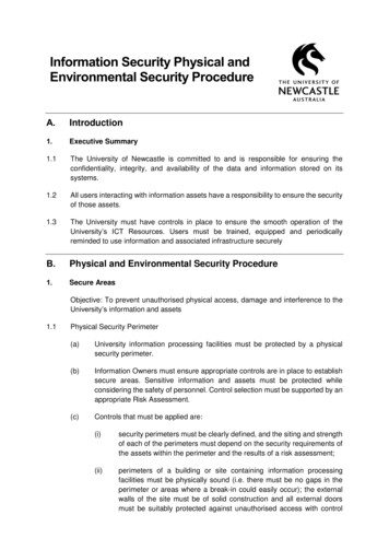
CenterCenterCenterWiring DiagramValet switchControl buttonLEDStatus LEDControl Center 6211TValet switchControl buttonLEDStatus LEDLIGHT FLASH POLARITY(10A (MAXIMUM) FUSE JUMPER)Control CenterBitwriter/SmartStart Port10A FUSEMINI ATMRPN: 8540Thermistor/Temp SensorSensor 1Remote Start10-pin HarnessSensor 25x04IMPORTANT! Neutral Safetyswitch must be plugged inand in the ON positionNeutral SafetySwitchONRF Portfor IVUMain 6-pinHarnessDoor LockPortControl CenterD2D Port (for externalXpresskit interface module)Aux/Shutdown/Trigger 24-pin HarnessNote: Sensor ports 1 and 2 cannot support sensor 508D due to current limitations. These ports are alsoconstant power and ground connections.112198765432110181110531181091 2012 Directed. All rights reserved.125
Wiring ConnectionsMain Harness, 6-pin connector1RED( )12VDC CONSTANT INPUT2BLACK(-) CHASSIS GROUND3BROWN( ) SIREN OUTPUT4WHITE/BROWNLIGHT FLASH ISOLATION WIRE - PIN 87a of onboard relay5WHITELIGHT FLASH OUTPUT - Pin 30 of light flash relay6ORANGE(-) 500mA GROUND WHEN ARMED OUTPUTAuxiliary/Shutdown Harness, 24-pin connectorPINK/WHITE1 2 312 VIOLET/WHITEBLACK/WHITE1324 GREEN/WHITEINSERTION/WIRE SIDE1PNK/WHITE(-) 200mA Ignition 2/Flex OUTPUT2BLUE/WHITE(-) 200mA 2ND STATUS /REAR DEFOGGER OUTPUT3RED/WHITE(-) 200mA TRUNK RELEASE OUTPUT4BLACK/YELLOWPINK/WHITE1 3 5(-) 200mA DOME23LIGHTOUTPUTVIOLET/WHITE5DARK BLUE(-) 200mA STATUS OUTPUT67WHITE/BLACK*(-) 200mA AUX 3 OUTPUTBLACK/WHITE 2 4 624 GREEN/WHITEWHITE/VIOLET*(-) 200mA SIDEAUX 1 OUTPUTINSERTION/WIRE8ORANGE/BLACK*(-) 200mA AUX 4 OUTPUT9GRAY(-) HOOD PIN INPUT (NC OR NO)10BLUE(-) TRUNK PIN/INSTANT TRIGGER INPUT (N/C OR N/O)11WHITE/BLUE**ACTIVATION INPUT12VIOLET/WHITE***TACHOMETER INPUT13BLACK/WHITE****(-) NEUTRAL SAFETY /PARKING BRAKE INPUT14GREEN/BLACK(-) 200mA FACTORY ALARM DISARM OUTPUT15GREEN***(-) DOOR INPUT (N/C¹ or N/O¹)16BROWN/BLACK(-) 200mA HORN HONK OUTPUT17PINK(-) 200mA IGNITION 1 OUTPUT18VIOLET***( ) DOOR INPUT19VIOLET/BLACK*(-) 200mA AUX 2 OUTPUT20BROWN( ) BRAKE SHUTDOWN INPUT21VIOLET/YELLOW(-) 200mA STARTER OUTPUT22GRAY/BLACK(-) DIESEL WAIT TO START INPUT23ORANGE(-) 200mA ACCESSORY OUTPUT24GREEN/WHITE(-) 200mA FACTORY ALARM ARM OUTPUT*Aux channels with the 4 button remote can only be accessed with channel linking to lock, unlock orremote start.**Connect this wire to ground through an optional momentary switch for turbo timer mode activation (4button remote control).*** Required connection for manual transmission vehicles.6 2012 Directed. All rights reserved.
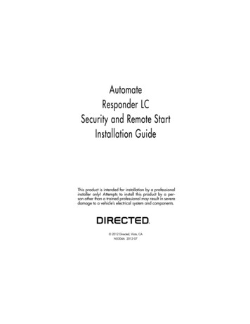
**** Ground this wire for automatic transmission vehicles or connect to the parking brake wire for manualtransmission vehicles.¹ The Normally Closed setting will only work if one of the vehicle's doors is connected. If more than one dooris to be monitored, then it is recommended to use the dome light wire in the vehicle or tech tip # 1921 onwww.directechs.com to interface with these types of vehicles.IMPORTANT: NEVER connect 200mA low current outputs directly to a motor or high current device WITHOUTa relay.Remote Start, 10-pin connector1PINK( ) IGNITION 1 INPUT/OUTPUT2RED/WHITE(87) FLEX RELAY 12V INPUT (30A FUSED)3ORANGE( ) ACCESSORY OUTPUT4VIOLET( ) STARTER OUTPUT (CAR SIDE OF THE STARTER KILL)5GREEN( ) STARTER INPUT (KEY SIDE OF THE STARTER KILL)6REDIGNITION 1 12V INPUT (30A FUSED)7PINK/WHITE(30) FLEX RELAY OUTPUT (car side of ign, acc or starter wire)8PINK/BLACK(87a) FLEX RELAY INPUT (key side of ign, acc or starter wire if needed)9RED/BLACKACCESSORY/STARTER RELAY 12V INPUT (30A FUSED)10NCNo ConnectionDoor Lock, 3-pin connector1BLUE(-) 500mA UNLOCK OUTPUT2EMPTYNOT USED3GREEN(-) 500mA LOCK OUTPUTWiring DescriptionsMain Harness, 6-pin connectorRed ( ) 12v Constant InputThis wire supplies power to the main unit's micro-controller. Remove the supplied fuse before connecting to thepositive terminal of the battery or a constant 12V supply to the ignition switch.Note: Always use a fuse within 12 inches of the ( ) 12V source. Do not use the 15A fuse in the harness forthis purpose as this fuse protects the module.Black (-) Chassis GroundThis wire is the main unit’s source of ground. DO NOT connect this wire to any factory ground points; theycan cause noise and/or current loss which can affect system performance. Ground the main unit and anyaccessories to the same point in the vehicle, (preferably the kick panel). Scrape away any paint and use afactory bolt or make your own ground with a self-tapping screw and a star washer.Brown ( ) Siren OutputThis wire supplies a ( ) output for the siren. Connect this wire to the Red wire of the siren and the Black wireof the siren to chassis ground, preferably at the same point you connect the main modules ground wire.White/Brown Light Flash Isolation Wire (PIN 87a of onboard relay)This wire is a parking light flash input from the vehicle light switch that connects to pin 87a of the on-boardlight flash relay. It is used for vehicles requiring light switch isolation during light flash output. For vehicles withmultiplex light circuits that require switch isolation, the on-board light flash fuse can be replaced with the specified resistor value (paying attention to the circuit polarity). See the following diagram for wiring information. 2012 Directed. All rights reserved.7
Light SwitchLIGHT FLASH POLARITYJUMPER DETAILxMultiplexWire in CarWhite/BrownxCutWhite10A FUSEMINI ATM5x04To control modulein carNote: Replace fuse with specified resistorvalue if connecting to multiplex light circuit(paying special attention to polarity selection)White Parking Light OutputThis wire connects to the parking light wire in the vehicle and is programmable for a or – output (see the"Light Flash Polarity Setting" on page 12 of this guide for polarity settings). The output pulses upon arming/disarming and while the alarm is triggering and can be programmed as a pulsed or constant output duringthe remote start runtime (see "Feature Menus" on page 19).Note: For parking light circuits that draw 10-amps or more, the internal jumper must be switched to a (-) lightflash output. (see the "Light Flash Polarity Setting" on page 12 of this guide for polarity settings) P/N 8617or a standard automotive SPDT relay must be used on the light flash output wire.Orange (-) 500mA Ground When Armed OutputThis wire supplies a (-) 500 mA ground as long as the system is armed. This output ceases as soon as thesystem is disarmed. The GWA can be hooked up to an optional voice module or any accessory that requiresa ground when armed.Note: This wire is also part of the anti-grind circuit which provides a ground during the remote start sequenceregardless of the system being armed or disarmed. If this function is not desired, turn off the anti-grind featurein programming (see "Feature Menus" on page 19).Auxiliary/Shutdown Harness, 24-pin connectorImportant! Never connect a 200 mA output directly to a motor or high current device without a relay.Pink/White (-) 200mA Programmable Flex Relay OutputThis wire is factory programmed as a (-) ignition output and can be programmed to function as a (-) accessoryor starter output. This wire is linked to the ( ) Flex relay output and programming affects both circuits. Thiswire can be used to drive any additional Ignition, accessory or starter wires (with an additional SPDT relayP/N 8617)Blue/White (-) 200mA Programmable 2nd Status/Rear Defogger OutputThis wire from factory supplies a (-) output as soon as the remote start process begins. This wire is typicallyused to activate an interface or any modules that require a ground whenever the remote start is activated.This wire can also be used as a rear defogger output. When programmed as a defogger output (latched orpulsed), it activates 10 seconds after the remote start engages (see "Feature Menus" on page 19).Note: When programmed as a Rear Defogger output, the vehicles interior temperature must be 55 F or belowto activate.8 2012 Directed. All rights reserved.
Red/White (-) 200mA Trunk Release OutputWhen the system receives the code controlling trunk release, for longer than 1.5 seconds, the RED/WHITEwire supplies an output as long as the transmission continues (up to 25 seconds max). This is often used tooperate a trunk/hatch release or other relay-driven function.Black/Yellow (-) 200mA Dome Light Supervision OutputConnect this wire to an optional Dome Light Supervision Relay. This wire outputs whenever the system isdisarmed and programmable to output when the vehicle ignition is turned off (see "Feature Menus" on page19). This wire also generates a pulsed output while the alarm is triggering.Dark Blue (-) 200mA Status OutputThis wire supplies a (-) output as soon as the remote start process begins. This wire is typically used to activatean interface or any modules that require a ground whenever the remote start is activated.White/Black (-) 200mA Programmable Aux 3 OutputThis wire supplies a (-) output whenever the transmitter button(s) controlling Aux 3 is pressed. This output canbe programmed to provide different types of outputs (see "Feature Menus" on page 19)White/Violet (-) 200mA Programmable Aux 1 OutputThis wire supplies a (-) output whenever the transmitter button(s) controlling Aux 1 is pressed. This output canbe programmed to provide different types of outputs (see "Feature Menus" on page 19)Orange/Black (-) 200mA Programmable Aux 4 OutputThis wire supplies a (-) output whenever the transmitter button(s) controlling Aux 4 is pressed. This output canbe programmed to provide different types of outputs (see "Feature Menus" on page 19)Gray (N/O or N/C) HOOD Pin InputConnect to a wire that changes state when the hood is opened. N/O rests at ground when the hood isOPEN, N/C rests at ground when the hood is CLOSED (see "Feature Menus" on page 19).Blue (N/O or N/C) Trunk Pin/Instant Trigger InputConnect to a wire that changes state when the trunk is opened. N/O rests at ground when the trunk isOPEN, N/C rests at ground when the trunk is CLOSED (see "Feature Menus" on page 19). This wire canalso be connected to full trigger outputs of an optional Directed single zone sensor.Note: This wire is NOT shunted during the remote start operation.White/Blue (-) Activation/Turbo Timer InputThis (-) input can be used to manually activate the remote start feature, it can also be used to activate theTurbo Timer Mode when the Turbo Timer feature is programmed ON (see "Feature Menus" on page 19).Wire an optional push button to activate (See the following diagram for wiring information).To White/Blue activationinput on systemNote: The switch is required to activate the Turbo Timer Mode when using a 4 button remote.Violet/White Tachometer InputThis input provides the module with information about the engine’s revolutions per minute (RPM’s). It can beconnected to the negative side of a coil in vehicles with conventional coils it may also be connected to thenegative side of a fuel injector wire. Once connected you must teach the system the tachometer signal of thevehicle. 2012 Directed. All rights reserved.9
Note: This connection is required when installing on a manual transmission vehicle.Black/White (-) Neutral Safety/Parking Brake InputConnect this wire to a ground source
6 RED IGNITION 1 12V INPUT (30A FUSED) 7 PINK/WHITE (30) FLEX RELAY OUTPUT (car side of ign, acc or starter wire) 8 PINK/BLACK (87a) FLEX RELAY INPUT (key side of ign, acc or starter wire if needed) 9 RED/BLACK ACCESSORY/STARTER RELAY 12V INPUT (30A FUSED) 10 NC No Connection Door Lock, 3-pin connector 1 BLUE (-) 500mA UNLOCK OUTPUT 2 EMPTY .