Transcription
16Hi HARDWARE INSTALLATION GUIDE
Table of ContentsSection 1Ratings . . . . . . . . . . . . . . . . . . . . . . . . . . . . . . . . . . . . . . . . . . . . . . . . . . . . . . . . . . . . . . . . . . . . . . .3Section 2Site Preparation . . . . . . . . . . . . . . . . . . . . . . . . . . . . . . . . . . . . . . . . . . . . . . . . . . . . . . . . . . . . . . . .3Section 3Unpacking the 4‐Post Rack Installation Assemblies . . . . . . . . . . . . . . . . . . . . . . . . . . . . . . . . . . .4Section 4A4‐Post Rack Installation with Standard Rails . . . . . . . . . . . . . . . . . . . . . . . . . . . . . . . . . . . . . . . . .5Section 4B4‐Post Rack Installation with Quick Mount Rails (square hole rack only) . . . . . . . . . . . . . . . . . .6Section 5Installing the Appliance in the 4‐Post Rack . . . . . . . . . . . . . . . . . . . . . . . . . . . . . . . . . . . . . . . . . .7Section 6Unpacking the 2‐Post Rack Installation Hardware . . . . . . . . . . . . . . . . . . . . . . . . . . . . . . . . . . . .8Section 72‐Post Rack Installation . . . . . . . . . . . . . . . . . . . . . . . . . . . . . . . . . . . . . . . . . . . . . . . . . . . . . . . . . .9Section 8Installing the Appliance in the 2‐Post Rack . . . . . . . . . . . . . . . . . . . . . . . . . . . . . . . . . . . . . . . . . .10Section 9Rear Panel Connections . . . . . . . . . . . . . . . . . . . . . . . . . . . . . . . . . . . . . . . . . . . . . . . . . . . . . . . . .11Section 1oFront Panel Operation . . . . . . . . . . . . . . . . . . . . . . . . . . . . . . . . . . . . . . . . . . . . . . . . . . . . . . . . . . .13NetSpective Web Filter 16Hi Hardware Installation GuidePage 2
1.RatingsAC input voltage:Input frequency range:Rated input current:2.100 ‐ 240V 50/60 Hz6.1‐2.6A (x2)Site PreparationSetup location, rack and appliance precautions Elevated Operating Ambient Temperature ‐ If installed in a closed or multi‐unit rack assembly, the operating ambienttemperature of the rack environment may be greater than room ambient temperature. Therefore, considerationshould be given to installing the equipment in an environment compatible with the maximum ambient temperature(Tma) specified by the manufacturer.Always keep the rack’s front door and all panels and components on the appliances closed when not servicing tomaintain proper cooling. Reduced Air Flow ‐ Installation of the equipment in a rack should be such that the amount of air flow required forsafe operation of the equipment is not compromised. Leave enough clearance, approximately 25 inches in the front,and 30 inches in the back of the rack to enable you to access appliance components and allow for sufficient air flow. Mechanical Loading ‐ Mounting of the equipment in the rack should be such that a hazardous condition is notachieved due to uneven mechanical loading.ALL RACKS MUST BE MOUNTED SECURELY. Ensure that all leveling jacks or stabilizers are properly attached to therack. If installing multiple appliances in a rack, make sure the overall loading for each branch circuit does not exceedthe rated capacity.Do not slide more than one appliance out from the rack at a time. Extending more than one appliance at a time mayresult in the rack becoming unstable. Install your appliance in the lower part of the rack because of its weight andalso for ease in accessing appliance components. Circuit Overloading ‐ Consideration should be given to the connection of the equipment to the supply circuit andthe effect that overloading of the circuits might have on overcurrent protection and supply wiring. Appropriateconsideration of equipment nameplate ratings should be used when addressing this concern. Reliable Earthing ‐ Reliable earthing of rack‐mounted equipment should be maintained. Particular attention shouldbe given to supply connections other than direct connections to the branch circuit (e.g. use of power strips).Install near appropriate AC outlets, and Ethernet hubs or individual jacks. Be sure to install an AC Power Disconnectfor the entire rack assembly. The Power Disconnect must be clearly marked. Ground the rack assembly properly toavoid electrical shock.NetSpective Web Filter 16Hi Hardware Installation GuidePage 3
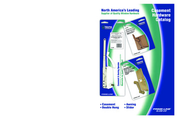
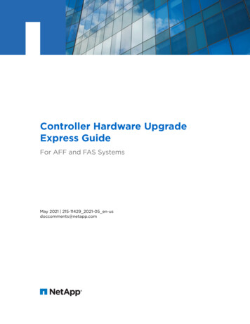
3.Unpacking the 4‐Post Rack Installation AssembliesVerify that the ship kit includes one of the following installation assembliesInstallation Assembly A ‐ Standard Rail Assemblieswith Mounting HardwareNOTE: Use the hardware suppliedwith your specific rack if differentfrom the hardware supplied inthis kit. Two power cords* A set of 4‐post rack mounting hardware**(Eight) M5 x 12Phillips flat head screws(Eight) M5 x 12cone washers(Ten) M5cage nuts* NOTE: Only two power cords willbe included in your ship kit evenif you receive multiple rail kits.(Two) 10‐32 x 3/4”Phillips pan head screws(used to secure the appliance in the rack)** NOTE: There may be additionalmounting hardware includedthat will not be used with thisinstallation assembly kit. A pair of 4‐post rack sliding chassis rail rack assemblies that attach directly to the rackRack rail assembly, inside viewAdjustable front rack rail assembly;ĂƩĂĐŚĞƐ ƚŽ ƚŚĞ ĨƌŽŶƚ ŽĨ ƚŚĞ ƌĂĐŬͿAdjustable rear rack rail assembly;ĂƩĂĐŚĞƐ ƚŽ ƚŚĞ ƌĞĂƌ ŽĨ ƚŚĞ ƌĂĐŬͿRack rail assembly, outside viewInstallation Assembly B ‐ Quick Mount Rails (for use in 4‐post racks with square holes only) Two power cords* Two 10‐32 x 3/4” Phillips pan head screws**(Two) 10‐32 x 3/4”Phillips pan head screws(used to secure the appliance in the rack) A pair of adjustable quick‐mount rack rail assemblies (requires no additional mounting hardware or tools)Quick-mount rack rail assembly, inside viewAdjustable front quick-mount rack rail assembly;ĂƩĂĐŚĞƐ ƚŽ ƚŚĞ ĨƌŽŶƚ ŽĨ ƚŚĞ ƌĂĐŬͿAdjustable rear quick-mount rack rail assembly;ĂƩĂĐŚĞƐ ƚŽ ƚŚĞ ƌĞĂƌ ŽĨ ƚŚĞ ƌĂĐŬͿQuick-mount rack rail assembly, outside viewNetSpective Web Filter 16Hi Hardware Installation GuidePage 4
4A. 4‐Post Rack Installation with Standard RailsLocate the mounting hardware and rack rail assemblies shown belowStep 1NOTE: The installation procedures forSections 6A below, and 6B, 4‐Post Rack,and on page 9 are for use with the railsand hardware provided in your ship kit.If different style rails are being used, orif your rack requires different hardware,refer to the instructions provided withyour rail’s or rack’s ship kit.Locate the two adjustable standard rack rail assemblies. Insert the tabs on the front section of the adjustablerack rail assembly through the openings in the rearsections of the assemblies. Check to make sure the adjustable rack railassemblies are connected correctly, then slide thefront section forward and the rear section back tokeep them from coming apart. These assembliesadjust to accommodate different rack depths.Rack bracket tabRack bracket tabs&ƌŽŶƚ ƐĞĐƟŽŶ ŽĨthe adjustablerack rail assemblyStep 2 Insert a cage nut into each of the squareholes in the rack you will be using as shown(three in the front and two in the rear).They click into place. Attach the rack/rail assemblies to the rackusing two M5 x 12 flat head screws andcone washersin the front and back. Theconvex side of the conewashers face towardthe rack. Make sure the rack/rail assemblies andscrews are aligned in the rack not onlyin the front and back, but are level inheight on the left and right sides for properalignment for appliance installation.NetSpective Web Filter 16Hi Hardware Installation GuideZĞĂƌ ƐĞĐƟŽŶ ŽĨthe adjustablerack rail assemblyEmptyholeAdjustable rack rail assembliesEmptyhole4-post rackEmptyholePage 5
4B. 4‐Post Rack Installation with Quick Mount Rails (square hole rack only)Locate the quick mount rack rail assemblies shown belowStep 1Locate the two adjustable quick‐mountrack rail assemblies. Insert the tabs on the front section of theadjustable rack rail assembly through theopenings in the rear sections of the assemblies.Rack bracket tabRack bracket tabs Check to make sure the adjustable rack railassemblies are connected correctly, then slidethe front section forward and the rear sectionback to keep them from coming apart. Theseassemblies adjust to accommodate differentrack depths.&ƌŽŶƚ ƐĞĐƟŽŶ ŽĨthe adjustablerack rail assemblyZĞĂƌ ƐĞĐƟŽŶ ŽĨthe adjustablerack rail assemblyStep 2 Quick‐mount rail Installation in thesquare hole rack:A. Insert the quick‐mount rail tabson the front of the rack railassembly through the selectedset of square holes in the rack.NOTE: There is a threaded hole between thetwo quick‐mount tabs in the rail assembly. Thishole will be used to secure the appliance in therack later in this guide.EmptyholeAdjustable quick-mountrack rail assembliesCD4-postrackQuick-mountrail tabs(angle view)Empty holeAB. Push the tabs into the holes in the rackuntil you hear the locking mechanismon the rail assembly click into place.The locking mechanism secures the railsto the rack.C. Slide the rail assembly to the back ofthe rack.D. In the rear, insert the quick‐mount rail tabsthrough the square holes level with the frontinstallation.E. Push the tabs into the holes until you hearthe rear locking mechanism click into place. Repeat these steps for the other side of the rack.*NetSpective Web Filter 16Hi Hardware Installation GuideQuick-mountrail tabs(side view)Quick-mount raillocking mechanismEBQuick-mountlockingmechanism* NOTE: Make sure the quick‐mount rail assemblies are aligned in therack not only in the front and back, but are level in height on the left andright sides for proper alignment for appliance installation.Page 6
5.Installing the Appliance in the 4‐Post Rack Align the inner fixed chassis rails on the appliance with the fixed chassis rack rail assemblies previously installedin the rack. Carefully slide the appliance into the rack rails until you hear the locking tabs on the chassis rails click into place. Push the appliance all the way into the rack until it stops. Secure the unit in the rack by inserting and tightening two 10‐32 x 3/4” Phillips pan head screws, one on each side.Adjustable rack rail assemblies(standard or quick-mount)Locking tabTwo 10-32 x 3/4”WŚŝůůŝƉƐ ŇĂƚͲŚĞĂĚ ƐĐƌĞǁƐ*NetSpective Web Filter 16Hi Hardware Installation GuideFixed chassis rail;ĂƩĂĐŚĞĚ ƉƌŝŽƌ ƚŽ ƐŚŝƉŵĞŶƚͿNOTE: When removing the appliancefrom your rack, you will need topress down on the locking tab inorder to release it from the rack.Carefully slide it out supporting theunit on both sides at all times.Page 7
6.Unpacking the 2‐Post Rack Installation HardwareVerify that the ship kit includes the following installation hardwareNOTE: Use the hardware suppliedwith your specific rack if differentfrom the hardware supplied inthis kit.Installation Hardware Two power cords* A set of 2‐post rack mounting hardware*** NOTE: Only two power cords willbe included in your ship kit evenif you receive multiple rail kits.(Eight) M5 x 12Phillips flat head screws(Twenty‐two) M4 x 4Phillips truss head screws(Two) 10‐32 x 3/4”Phillips pan head screws(used to secure the appliance in the rack)** NOTE: There may be additionalmounting hardware includedthat will not be used with thisinstallation assembly kit. Two pairs of 2‐post rack mounting brackets4 (Four)Fixed 2-post rack bracketsInside front viewOutside front view A pair of 2‐post rack mounting brackets with threaded holes2 (Two)Fixed 2-post rack bracketswith threaded holesInside front viewOutside front view A pair of 2‐post rack assemblies that attach directly to the rack2 Post Rack rail assembly, inside view2 Post Rack rail assembly, outside viewNetSpective Web Filter 16Hi Hardware Installation GuidePage 8
7.NOTE: The installation procedures belowfor Section 9, 2‐Post Rack are for use withthe rails and hardware provided in your shipkit. If different style rails are being used,or if your rack requires different hardware,refer to the instructions provided with yourrail’s or rack’s ship kit.2‐Post Rack InstallationUnpack the appliance and locate the mounting hardwareStep 1Locate the two long and six short rack bracketsthat came in your ship kit.A. Securely attach the set of short brackets withthe threaded screw holes to the long bracketin the front as shown. Use two M4 truss headscrews for each bracket.B. Loosely attach one set of the other shortbrackets to the long fixed bracket as shownusing one M4 truss head screw on eachbracket. The three holes on the flap will facetoward the back for later attachment to the2‐post rack.C ŽŶŐ ďƌĂĐŬĞƚ ŵĂůů ĮdžĞĚƌĂĐŬ ďƌĂĐŬĞƚƐBCA ŵĂůů ĮdžĞĚƌĂĐŬ ďƌĂĐŬĞƚƐB ŵĂůů ĮdžĞĚƌĂĐŬ ďƌĂĐŬĞƚƐ ǁŝƚŚƚŚƌĞĂĚĞĚ ŚŽůĞƐC. Loosely attach the remaining set of shortbrackets to the long fixed bracket as shownusing one M4 truss head screw on eachbracket. The three holes on the flap will facetoward the front for later attachment to the2‐post rack.AKŶĞ Dϰ ƚƌƵƐƐŚĞĂĚ ƐĐƌĞǁdǁŽ Dϰ ƚƌƵƐƐ ŚĞĂĚ ƐĐƌĞǁƐNOTE: Once the assembled rails are attachedto the rack, securely tighten the single screwson steps B and C.Step 2Attach the assembled brackets to the2‐post rack.A. Insert two M5 x 12 flat head screws throughthe short brackets into the 2‐post rack (in thefront and back of the rack as shown) andtighten. Make sure the brackets are alignedand level in height, not only in the front andback but also on the left and right sides.AAADϱ dž ϭϮ ŇĂƚ ŚĞĂĚ ƐĐƌĞǁƐ*;ƚǁŽ ĨƌŽŶƚ ĂŶĚ ƚǁŽ ƌĞĂƌͿ AB. Tighten each of the single screws on the smallfixed brackets (located on either side of therack) to secure the brackets in the rack andensure appliance stability.BBNetSpective Web Filter 16Hi Hardware Installation GuidePage 9
8.Installing the Appliance in the 2‐Post Rack Align the inner fixed chassis rails on the appliance with the fixed chassis rack rail assemblies previously installedin the rack. Carefully slide the appliance into the rack rails until you hear the locking tabs on the chassis rails click into place. Push the appliance all the way into the rack until it stops. Secure the unit in the rack by inserting and tightening two 10‐32 x 3/4” Phillips pan head screws, one on each side. ŽĐŬŝŶŐ ƚĂďTwo 10-32 x 3/4”WŚŝůůŝƉƐ ŇĂƚͲŚĞĂĚ ƐĐƌĞǁƐ*NetSpective Web Filter 16Hi Hardware Installation Guide&ŝdžĞĚ ĐŚĂƐƐŝƐ ƌĂŝů;ĂƩĂĐŚĞĚ ƉƌŝŽƌ ƚŽ ƐŚŝƉŵĞŶƚͿNOTE: When removing the appliancefrom your rack, you will need to pressdown on the locking tab in order torelease it from the rack. Carefullyslide it out supporting the unit onboth sides at all times.Page 10
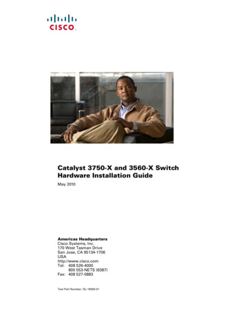
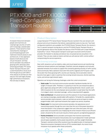
9.CAUTIONRear Panel ConnectionsAECBDJLISlide rail/mounted equipment is notto be used as a shelf or a work space.KFGN PM O QRSHTAPower Supply Module #1KPower Good LED #2BAC Power Inlet #1LPower Supply Lock #2CPower Supply #2M USB Port 1 (generation 2)DAC Power Inlet #2NUSB Port 2 (generation 2)ECOM PortOUSB Port 3 (generation 3)FRemote Management PortPUSB Port 4 (generation 3)G1 GbE Quad Port NIC CardQNetwork Interface Connection (NIC) #1HQuick Assist Accelerator CardRNetwork Interface Connection (NIC) #2IPower Good LED #1SVGA PortJPower Supply Lock #1T10G Ethernet Dual Port Fiber LC, PCIe 2.0 x8NetSpective Web Filter 16Hi Hardware Installation GuidePage 11
9.Rear Panel Connections (continued)12322Step 1: Connect the Ethernet cables.Step 2: Connect any other required cables.CAUTIONStep 3: Connect the power cords.Proceed to Section 10, Front Panel Operation on page 13.Power Supply Status LEDThere is a single bi‐color Power Good LED on each powersupply module to indicate power supply status. The LEDoperation is defined in the table below.Power Supply ConditionOutput ON and OKNo AC power to both power suppliesAC present / Only 5VSB on (PS off)NOTE: The server offers redundant, hot‐swap capability. Theconnections to AC mains should be made in a manner appropriateto local code and consistent with customer power distributionwith or without redundant sources.LED StateGREENOFFAMBERAC cord unplugged or AC power lost; with a secondpower supply in parallel still with AC input powerOFFPower supply warning events where the powersupply continues to operate; high temp, high power,high current, slow fan1Hz BlinkingAMBERPower supply critical event causing a shutdown;failure, OCP, OVP, fan failThe power supply is hot‐swappable only when you have a serverwith redundant power supplies installed. If you only have onepower supply installed, before removing or replacing the powersupply, you must first take the server out of service, turn off allperipheral devices connected to the server, turn off the server bypressing the power button, and unplug the AC power cord fromthe server or wall outlet.AMBERIn normal operation the Power Good LED on Power Supply Module 1and Module 2 will be SOLID GREEN. If the power is down, both LEDswill BLINK GREEN.NetSpective Web Filter 16Hi Hardware Installation GuidePage 12
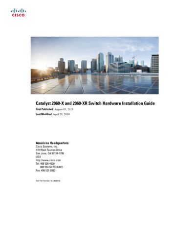
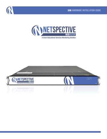
10. Front Panel Operation12Power on the appliance1. Remove the front bezel (if it is on theappliance) by pressing in on the leftside of the bezel to release it from theappliance.2. Press the power button located on thefar right on the front side of the appliance.hŶŝƚ / ƵƩŽŶDƵůƟͲĨƵŶĐƟŽŶ Blue LED LJƐƚĞŵ ŝĚĞŶƟĮĐĂƟŽŶŝŶĚŝĐĂƚŽƌRed LED LJƐƚĞŵ ĂůĞƌƚŝŶĚŝĐĂƚŽƌNIC2 LEDHDD LEDNIC1 LEDZĞƐĞƚ ƵƩŽŶPower LED3I/O Power ƵƩŽŶ3. Once the system has been powered on,replace the bezel.NetSpective Web Filter 16Hi Hardware Installation GuidePage 13
Corporate OfficeGrom Educational Services, Inc.3280 Pointe Parkway, Suite 2500Peachtree Corners, GA 30092Phone ‐ 678‐459‐1410Fax ‐ 678‐459‐1411Email ‐ pyright Grom Educational Services 2018
NetSpective Web Filter † 16Hi Hardware Installation Guide Page 3 1. Ratings AC input voltage: 100 ‐ 240V Input frequency range: 50/60 Hz Rated input current: 6.1‐2.6A (x2) Setup location, rack and appliance precautions Elevated Operating Ambient Temperature ‐If installed in a closed or multi‐unit rack assembly, the operating ambient .